headlights MITSUBISHI ECLIPSE 1991 Service Manual
[x] Cancel search | Manufacturer: MITSUBISHI, Model Year: 1991, Model line: ECLIPSE, Model: MITSUBISHI ECLIPSE 1991Pages: 1216, PDF Size: 67.42 MB
Page 495 of 1216

FUEL SYSTEM - Service Adjustment Procedures <1.8L Engine>l-4-41
SERVICE ADJUSTMENT PROCEDURES
CURB IDLE SPEED INSPECTION
CautionNlIFiiAE
The improper setting (throttle valve opening) will increase
exhaust gas temperature at deceleration, reducing catalystlife greatly and deteriorating exhaust gas cleaning per-
formance. It also has effect on fuel consumption and
engine braking.
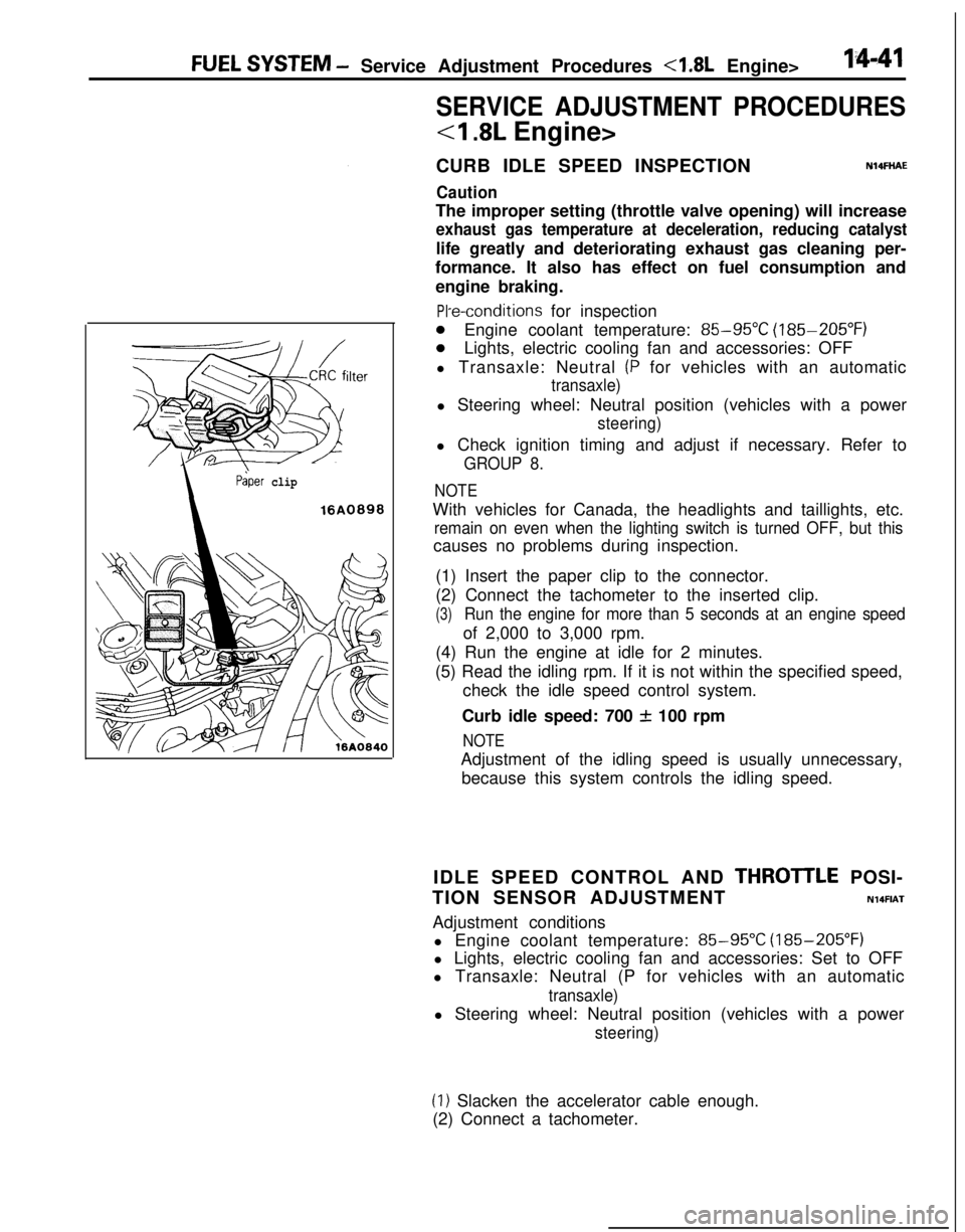
ilter
Paper clip
16A0898
PI-e-conditions for inspection
0Engine coolant temperature: 85-95°C (185-205°F)
0Lights, electric cooling fan and accessories: OFF
l Transaxle: Neutral
(P for vehicles with an automatic
transaxle)l Steering wheel: Neutral position (vehicles with a power
steering)l Check ignition timing and adjust if necessary. Refer to
GROUP 8.
NOTEWith vehicles for Canada, the headlights and taillights, etc.
remain on even when the lighting switch is turned OFF, but thiscauses no problems during inspection.
(1) Insert the paper clip to the connector.
(2) Connect the tachometer to the inserted clip.
(3)Run the engine for more than 5 seconds at an engine speedof 2,000 to 3,000 rpm.
(4) Run the engine at idle for 2 minutes.
(5) Read the idling rpm. If it is not within the specified speed,
check the idle speed control system.
Curb idle speed: 700
f 100 rpm
NOTEAdjustment of the idling speed is usually unnecessary,
because this system controls the idling speed.
IDLE SPEED CONTROL AND
THROTlLE POSI-
TION SENSOR ADJUSTMENT
N14FIATAdjustment conditions
l Engine coolant temperature:
85-95X (185-205°F)
l Lights, electric cooling fan and accessories: Set to OFF
l Transaxle: Neutral (P for vehicles with an automatic
transaxle)l Steering wheel: Neutral position (vehicles with a power
steering)
(1) Slacken the accelerator cable enough.
(2) Connect a tachometer.
Page 502 of 1216

14-48FUEL SYSTEM - Service Adjustment Procedures <2.0L Engine>
SERVICE ADJUSTMENT PROCEDURES
<2.0L DOHC Engine>
CURB IDLE SPEED INSPECTION
Caution
N14FHADThe improper setting (throttle valve opening) will increase
exhaust gas temperature at deceleration, reducing
catalys-tic converter life greatly and deteriorating exhaust gas
cleaning performance. It also has effect on fuel ‘consump-
tion and engine braking.
Pre-conditions for inspection
l Engine coolant temperature:
85-95°C (185-205°F)
l Lights, electric cooling fan and accessories: OFF
lTransaxle: Neutral (P for vehicles with automatic transaxle)l Steering wheel: Neutral position (vehicles with a power-
steering)l Check ignition timing and adjust if necessary. Refer to
GROUP 8.
NOTEWith vehicles for Canada, the headlights and taillights, etc.
remain on even when the lighting switch is turned OFF, but thiscauses no problems during inspection.
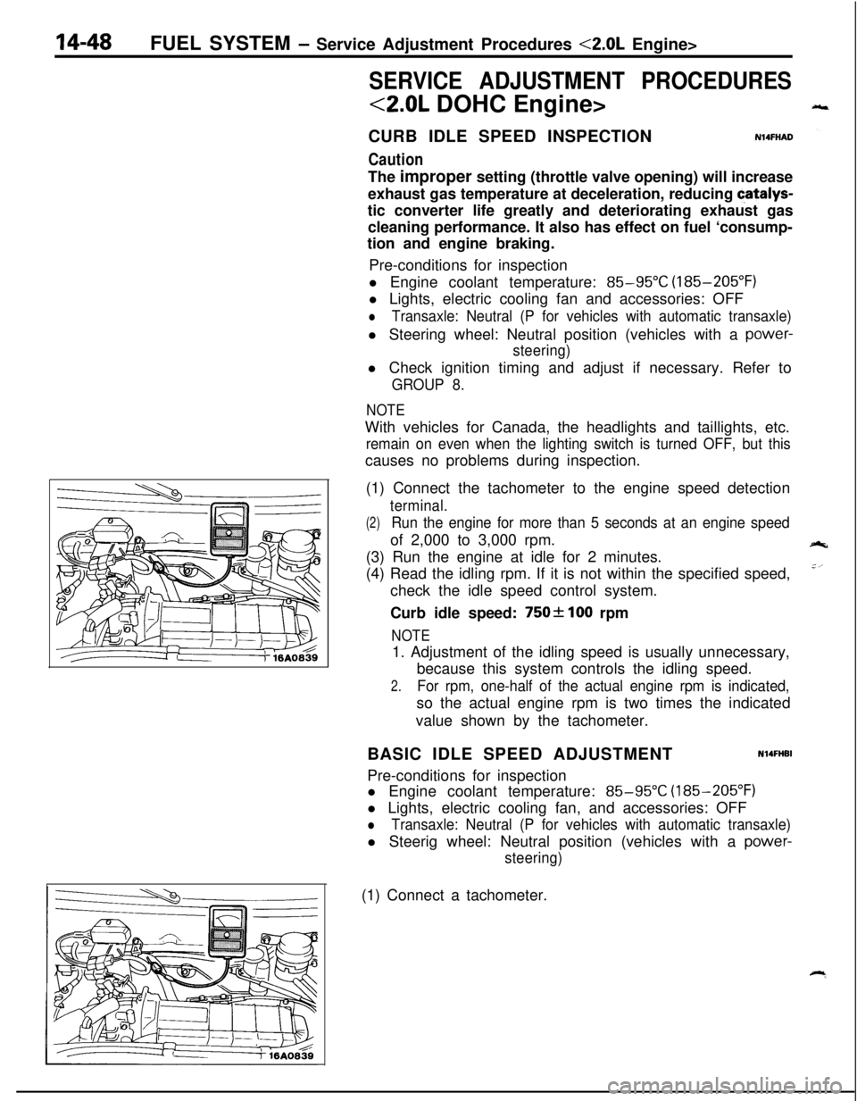
(1) Connect the tachometer to the engine speed detection
terminal.
(2)Run the engine for more than 5 seconds at an engine speedof 2,000 to 3,000 rpm.
(3) Run the engine at idle for 2 minutes.
(4) Read the idling rpm. If it is not within the specified speed,
check the idle speed control system.
Curb idle speed:
750f 100 rpm
NOTE1. Adjustment of the idling speed is usually unnecessary,
because this system controls the idling speed.
2.For rpm, one-half of the actual engine rpm is indicated,so the actual engine rpm is two times the indicated
value shown by the tachometer.
BASIC IDLE SPEED ADJUSTMENT
N14FHBIPre-conditions for inspection
l Engine coolant temperature:
85-95°C (185-205°F)
l Lights, electric cooling fan, and accessories: OFF
lTransaxle: Neutral (P for vehicles with automatic transaxle)l Steerig wheel: Neutral position (vehicles with a
power-
steering)(1) Connect a tachometer.
Page 1095 of 1216

BODY - Fender
FENDER
:- REMOVAL AND INSTALLATION
-.
Pre-removal Operation0 Removal of Front Garnish
(Refer to P.23-47.)l Removal of Front Turn Signal Light
and Front Combination Light
(Refer to GROUP 8-Front Combi-
nation Light)
l Removal of Headlight Lower Bezel
(Refer to GROUP
8-Headlights)l Removal of Side Air Dam
(Refer to
P.23-74.)LLu23KAAr
Post-installation Operation0 Installation of Side Air Dam
(Refer to P.23-74.)l Installation of Headlight Lower
Bezel
(Refer to GROUP
8-Headlight)0 Installation of Front Turn Signal
Light and Front Combination Light
(Refer to GROUP
8-Front Combi-
nation Light)
0 Installation of Front Garnish
(Refer to P.23-47.)J
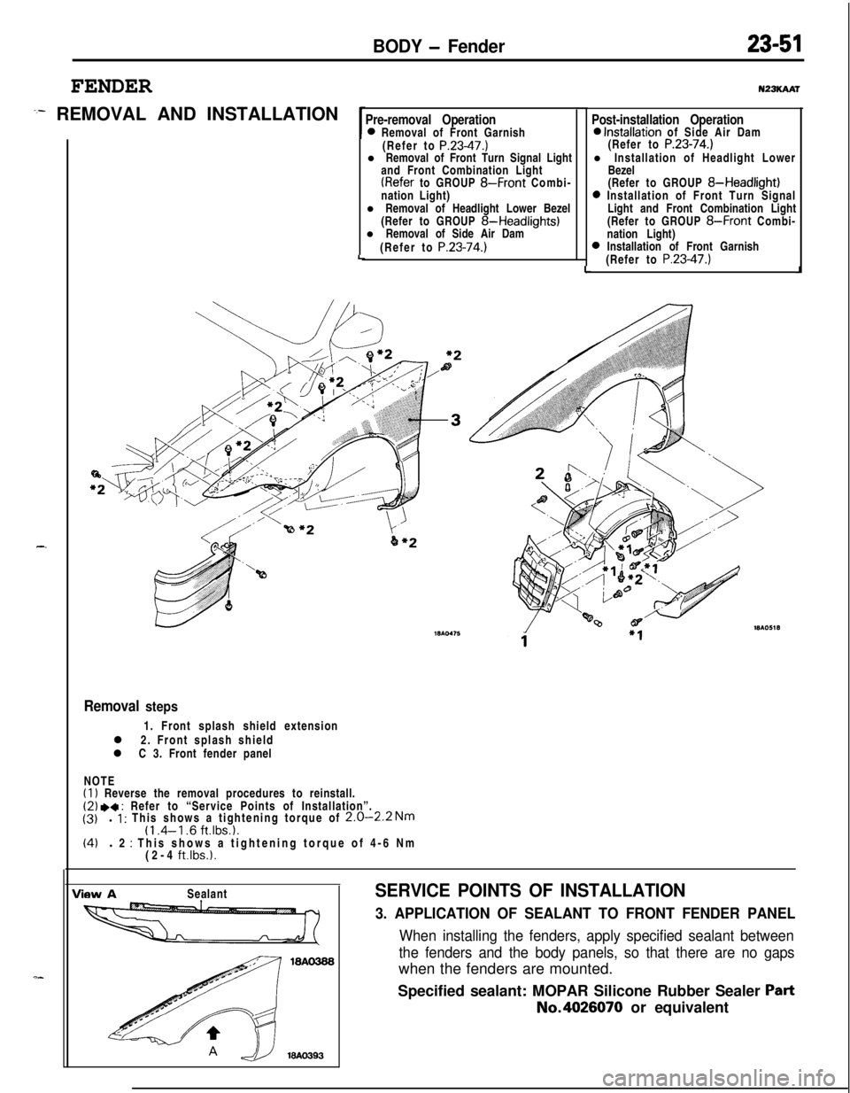
Removal steps1. Front splash shield extension
l 2. Front splash shield
l C 3. Front fender panel
NOTE
(1) Reverse the removal procedures to reinstall.(2) .a : Refer to “Service Points of Installation”.
(3)l 1 : This shows a tightening torque of 2.0-2.2 Nm(1 .4-l .6 ft.lbs.1.(4)l 2 : This shows a tightening torque of 4-6 Nm
(2-4 ft.lbs.1.
View ASealantSERVICE POINTS OF INSTALLATION
3. APPLICATION OF SEALANT TO FRONT FENDER PANEL
When installing the fenders, apply specified sealant between
the fenders and the body panels, so that there are no gapswhen the fenders are mounted.
Specified sealant: MOPAR Silicone Rubber Sealer
PartNo.4026070 or equivalent