warning light MITSUBISHI ECLIPSE 1991 Owner's Guide
[x] Cancel search | Manufacturer: MITSUBISHI, Model Year: 1991, Model line: ECLIPSE, Model: MITSUBISHI ECLIPSE 1991Pages: 1216, PDF Size: 67.42 MB
Page 1063 of 1216
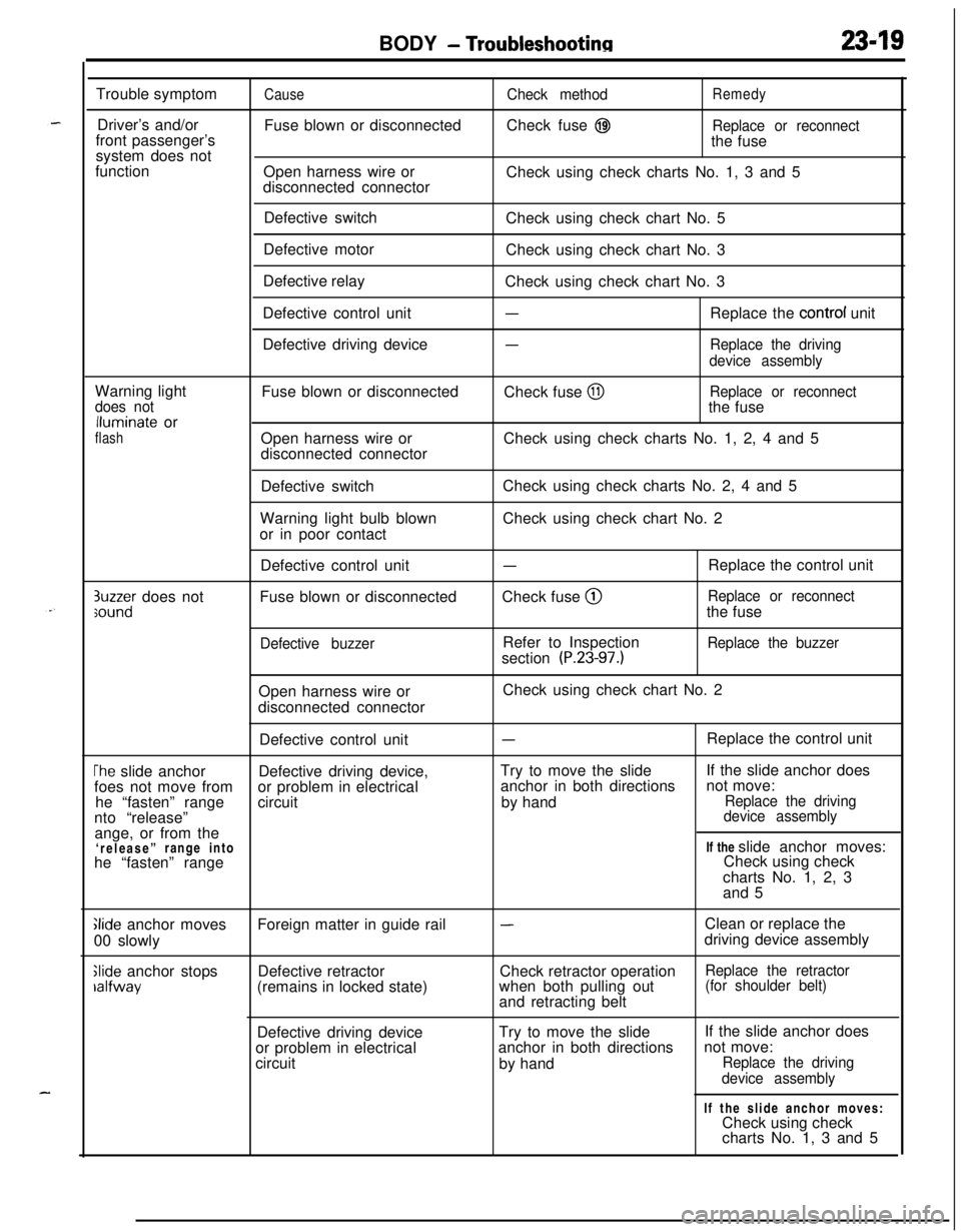
BODY - Troubleshootinn2349Trouble symptom
Driver’s and/or
front passenger’s
system does not
function
CauseFuse blown or disconnected
Open harness wire or
disconnected connectorCheck methodRemedyCheck fuse
@IReplace or reconnectthe fuse
Check using check charts No. 1, 3 and 5
Defective switch
Defective motor
Defective relay
Defective control unit
Defective driving deviceCheck using check chart No. 5
Check using check chart No. 3
Check using check chart No. 3
-Replace the control unit
-Replace the driving
device assemblyWarning light
does notlluminate or
flashFuse blown or disconnected
Open harness wire or
disconnected connectorCheck fuse
@IReplace or reconnectthe fuse
Check using check charts No. 1, 2, 4 and 5
Defective switch
Warning light bulb blown
or in poor contactCheck using check charts No. 2, 4 and 5
Check using check chart No. 2
3uzzer does notsoundDefective control unit
Fuse blown or disconnected
Defective buzzer
-Check fuse @
Refer to Inspection
section
(P.23-97.)Replace the control unit
Replace or reconnectthe fuse
Replace the buzzerOpen harness wire or
disconnected connectorCheck using check chart No. 2
Defective control unit
-Replace the control unit
The slide anchorDefective driving device,Try to move the slideIf the slide anchor does
foes not move fromor problem in electricalanchor in both directionsnot move:
he “fasten” rangecircuitby hand
Replace the drivingnto “release”device assemblyange, or from the
‘release”range intoIf the slide anchor moves:
he “fasten” rangeCheck using check
charts No. 1, 2, 3
and 5
Glide anchor moves
00 slowly
Slide anchor stopsralfwayForeign matter in guide rail
Defective retractor
(remains in locked state)
-Clean or replace the
driving device assembly
Check retractor operation
Replace the retractorwhen both pulling out(for shoulder belt)and retracting belt
Defective driving deviceTry to move the slide
or problem in electricalanchor in both directions
circuit
by handIf the slide anchor does
not move:
Replace the driving
device assemblyIf the slide anchor moves:
Check using check
charts No. 1, 3 and 5
Page 1064 of 1216
23-20BODY - Troubleshooting
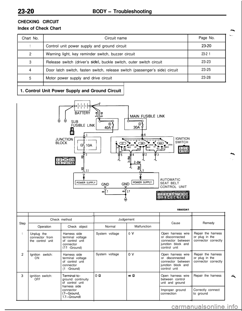
CHECKING CIRCUITIndex of Check Chart
Chart No.Circuit name
1Control unit power supply and ground circuit
2Warning light, key reminder switch, buzzer circuit
3Release switch (driver’s side), buckle switch, outer switch circuit
4Door latch switch, fasten switch, release switch (passenger’s side) circuit
5Motor power supply and drive circuit
1. Control Unit Power Supply and Ground Circuit
Page No.
23-20
23-2 1
23-23
23-25
23-28IGNITION
SWITCH
,\--AUTOMATIC
SEAT BELT
CONTROL UNIT
Step
1
2
3Check method
Operation
Unplug the
connector from
the control unit
Ignition switch:
ONignition switch:
OFFCheck object
Harness side
terminal voltage
of control unit
connector
(I 1 -Ground)
Harness side
terminal voltage
of control unit
connector
(1 -Ground)
Terminal-to-ground continuity
of control unit
harness side
connector
(7-Ground,17-Ground)
TJudgement
NormalMalfunction
System voltage0 VCauseOpen harness wire
or disconnected
connector between
junction block and
control unitRemedy
Repair the harness
or plug in the
connector correctly
System voltage
0 V
Open harness wire
or disconnected
connector between
junction block and
control unitRepair the harness
or plug in the
connector correctly
00allOpen harness wire
between control
unit and groundRepair the harness
Improper groundCorrectly connect
connectionto ground
Page 1065 of 1216
BODY - Troubleshooting23-21
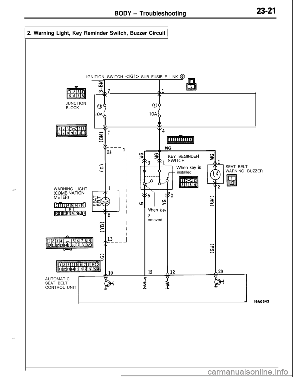
1 2. Warning Light, Key Reminder Switch, Buzzer Circuit 1IIJUNCTION
BLOCK
WARNING LIGHT
gCTy4;NATION
c-7,,7L,,l7,/\
00IOA
IOA
2:y47
.---
141I
I
I
I
I
I
1I
3
2
11
I
I
I13
-I_---
10IGNITION SWITCH
SEAT BELT
CONTROL UNIT
t
11 WG
KEY REMINDER
6
\IL!>
Nhen ke
8emoved
13
+ installed
J
2
1SEAT BELT
WARNING BUZZER
20
w
IIem
Page 1066 of 1216
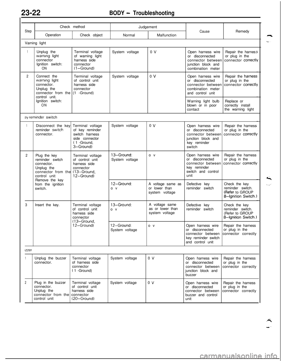
23-22BODY - TroubleshootingCheck method
StepOperation
Check object
Varning lightJudgementCauseRemedy
NormalMalfunction
1Unplug theTerminal voltagewarnrng light
of warning light
connector
harness side
Ignition switch:
connector
ON(I-Ground)
2Connect the
Terminal voltagewarnrng light
of control unit
connector.
harness side
Unplug theconnector
connector from the (1 -Ground)
control unit.
Ignition switch:
ON
ey reminder switchSystem voltage
System voltage0 V
0 VOpen harness wireRepair the harnes:
or disconnectedor plug in the
connector between connector
correct1junction block and
combination meter
Open harness wireRepair the harries:
or disconnectedor plug in the
connector between connector
correctl!combination meter
and control unit
Warning light bulbReplace or
blown or in poorcorrectly install
contactthe warning light
1Disconnect the key Terminal voltageSystem voltage0 VOpen harness wireRepair the harness
reminder switchof key reminder
or disconnectedor plug in the
connector.
switch harnessconnector between connector
correct11side connector
junction block and
t 1 -Ground,
key reminderS-Ground)switch
2Plug the key
Terminal voltage13-Ground:ovOpen harness wireRepair the harness
reminder switchof control unitSystem voltageor disconnectedor plug in the
connector.
harness sideconnector between connector
correct11Unplug theconnectorkey reminder
connector from the
(13-Ground,switch and control
control unit12-Ground)unit
Remove the key
from the ignition
12-Ground:A voltage same asDefective keyCheck the key
switch.ovor lower thanreminder switchreminder switch.
system voltage(Refer to GROUP
84gnition Switch.1
3Insert the key.Terminal voltage
13-Ground:A voltage same
as or lower thanDefective keyCheck the key
of control unit
ovreminder switchreminder switch.
harness sidesystem voltage
(Refer to GROUP
connector
84gnition Switch.1(13-Ground,12-Ground)12-Ground:ovOpen harness wireRepair the harness
System voltageor disconnectedor plug in the
connector between connector correctly
key reminder switch
and control unit
lzzer
1Unplug the buzzer
Terminal voltageSystem voltage0 VOpen harness wireRepair the harness
connector.of harness side
or disconnectedor plug in the
connector
connector between connector correctly
t 1 -Ground)
junction block and
buzzer
2Plug in the buzzer
Terminal voltageSystem voltage0 VOpen harness wireRepair the harness
connector.
of control unit
or disconnectedor plug in the
Unplug the
harness side
connector between connector correctly
connector from the connector
buzzer and control
control unit
(20-Ground)unit
Page 1073 of 1216
.-
BODY - Troubleshooting
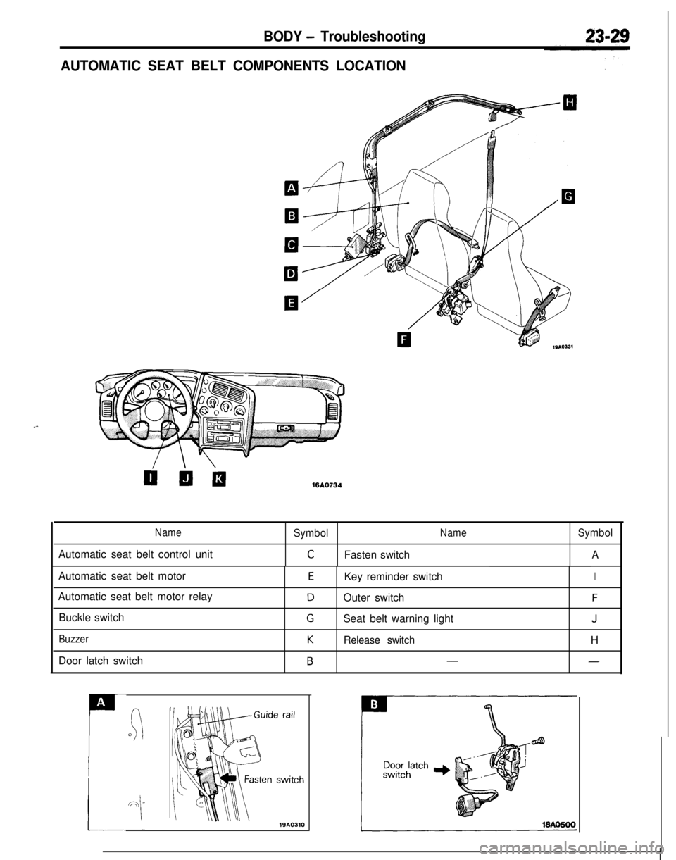
AUTOMATIC SEAT BELT COMPONENTS LOCATION
WA0734
NameSymbolNameSymbolAutomatic seat belt control unit
CFasten switchAAutomatic seat belt motor
Automatic seat belt motor relay
Buckle switch
BuzzerDoor latch switch
EKey reminder switchI
DOuter switchF
GSeat belt warning lightJ
KRelease switchH
B--
A
P
(:0
Page 1159 of 1216
HEATERS AND AIR CONDITIONING - Service Adjustment Procedures 24-15
Liquid
line
\Liquid lineI
ILiquid lineHigh pressure
hose2010439
detector torch
Electric leakAdetector tester
2OUO338
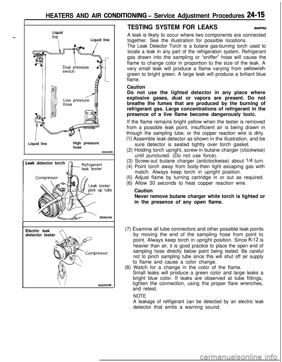
TESTING SYSTEM FOR LEAKSNUFFADA leak is likely to occur where two components are connected
together. See the illustration for possible locations.
The Leak Detector Torch is a butane gas-burning torch used to
locate a leak in any part of the refrigeration system.Refrigerantgas drawn into the sampling or “sniffer” hose will cause the
flame to change color in proportion to the size of the leak. A
very small leak will produce a flame varying from yellowish-
green to bright green. A large leak will produce a briliant blue
flame.Caution
Do not use the lighted detector in any place where
explosive gases, dust or vapors are present. Do not
breathe the fumes that are produced by the burning of
refrigerant gas. Large concentrations of refrigerant in the
presence of a live flame become dangerously toxic.
If the flame remains bright yellow when the tester is removed
from a possible leak point, insufficient air is being drawn in
through the sampling tube, or the copper reaction wire is dirty.
(1) Assemble leak detector as shown in the illustration, and be
sure detector is seated tightly over torch gasket.
(2) Holding torch upright, screw-in butane charger (clockwise)
until punctured. (Do not use force).
(3) Screw-out butane charger (anticlockwise) about
l/4 turn.
(4) Point torch away from body-then light escaping gas with
match. Always keep torch in upright position.
(5) Adjust flame by turning cartridge in or out as required.
(6) Allow 30 seconds to heat copper reaction wire.
Caution
Never remove butane charger while torch is lighted or
in the presence of any open flame.
(7) Examine all tube connectors and other possible leak points
by moving the end of the sampling hose from point to
point. Always keep torch in upright position. Since
R-12 is
heavier than air, it is good practice to place the open end of
sampling hose directly below point being tested. Be careful
not to pinch sampling tube since this will shut off air supplyto flame and cause a color change.
(8) Watch for a change in the color of the flame.
Small leaks will produce a green color and large leaks a
bright blue color. If leaks are observed at tube fittings,
tighten the connection, using the proper flare wrenches,
and retest.
NOTE
A leakage of refrigerant can be detected by an electric leakdetector that emits a warning sound.