ground clearance MITSUBISHI ECLIPSE 1991 Service Manual
[x] Cancel search | Manufacturer: MITSUBISHI, Model Year: 1991, Model line: ECLIPSE, Model: MITSUBISHI ECLIPSE 1991Pages: 1216, PDF Size: 67.42 MB
Page 25 of 1216
INTRODUCTION AND MASTER TROUBLESHOOTING - :;k%ii::& and25
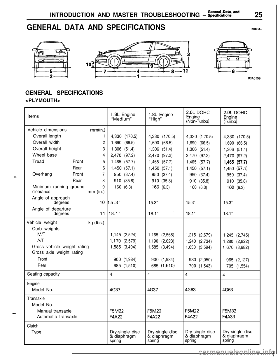
GENERAL DATA AND SPECIFICATIONSNOOHA-
OOAOl59
GENERAL SPECIFICATIONS
z-
A-l
.8L Engine1.8L Engine2.0L DOHC2.0L DOHCItems“Medium”“High”~%n?urbo):Tz%$
Vehicle dimensions
mm(in.)Overall length
14,330(170.5)4,330(170.5)4,330(I 70.5)4,330(170.5)Overall width
21,690(66.5)1,690(66.5)
1,690
(66.5)
1,690(66.5)Overall height
31,306(51.4)1,306(51.4)1,306(51.4)
1,306(51.4)Wheel base
4
2,470(97.2)2,470(97.2)2,470(97.2)2,470(97.2)Tread Front
5
1,465(57.7)
1,465(57.7)
1,465
(57.7)1,465(57.7)
Rear6
1,450(57.1)1,450(57.1)1,450(57.1)1,450(57:l i
Overhang Front
7950(37.4)950(37.4)950(37.4)
950(37.4)
Rear
8
910(35.8)910(35.8)910(35.8)910(35.8)Minimum running ground
9
160(6.3)160(6.3)
160(6.3)160(6.3)clearancemm (in.)
Angle of approach
degrees10 15.3”15.3”15.3”
15.3”Angle of departure
degrees11 18.1”
18.1” ’18.1“
18.1”Vehicle weight
kg (Ibs.)
Curb weights
M/T
1,145(2,524)
1,165(2,568)
1,215
(2,679)
1,245(2,745)
AIT1 ,I 70(2,579)
1,190(2,623)
1,240
(2,734)
1,280(2,822)Gross vehicle weight rating
1,585(3,494)1,585(3,494)
1,630
(3,594)‘I ,670(3,682)Gross axle weight rating
Front
900(1,984)900(1,984)930(2,050)965(2,127)
Rear
685(1,510)685(1,510)
700
(1,543)705‘(1,554)Seating capacity
4
444
EngineModel No.
4G3746374G634G63
TransaxleModel No.
Manual transaxle
F5M22F5M22F5M22F5M33Automatic transaxle
F4A22F4A22F4A22F4A33
Clutch
TypeDry-single discDry-single discDry-single discDry-single disc& diaphragm& diaphragm& diaphragm& diaphragm
springspringspringspring
Page 26 of 1216
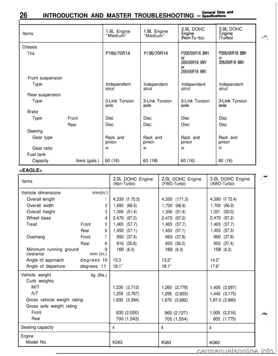
26INTRODUCTION AND MASTER TROUBLESHOOTING - :;:%:a=and
Items
Chassis
TireFront suspension
TypeRear suspension
We
Brake
Type
SteeringGear typeFront
RearGear ratio
Fuel tank
Capacityliters (gals.)
1.8L Engine
“Medium”Pl85/70R14
PI 85/70Rl4
Independent
strut
Independentstrut
3l\Fk Torsion&k-k Torsion
Disc
DiscDisc
Disc
Rack and
pinion
03
Rack and
pinion
cn60 (16)
60
(16)
ItemsVehicle dimensions
mm(in.)Overall length
1Overall width
2Overall height
3Wheel base
4
TreadFront5
Rear6
OverhangFront7
Rear8Minimum running ground
9
clearancemm (in.)
Angle of approachdegrees
10Angle of departure
degrees 11
Vehicle weight
kg (Ibs.)Curb weightsMiT
Al-rGross vehicle weight rating
Gross axle weight rating
Front
RearSeating capacity
EngineModel No.
1.8L Engine
“Medium”2.0L DOHC
Kr%n?u rbo)
P205/55Rl6 89H
;;5/55R16 89V%55R16
88V
Independentstrut
zx;;k Torsion
Disc
Disc
Rack and
pinion
co60 (16)
2.0L DOHC
#b”;
P205/55Rl6 89
or
205155R16 88V
Independentstrut
3Lnk Torsion
Disc
Disc
Rack and
pinion
co
60 (16)
2.0L DOHC Engine(Non-Turbo)
4,330(I 70.5)
1,690(66.5)
1,306(51.4)
2,470(97.2)
1,465(57.7)
1,450(57.1)
950(37.4)
910(35.8)
160(6.3)
15.3
18.1”
1,230 (2,712)
1,255 (2,767)
1,630 (3,594)930 (2,050)
700 (1,543)
4
4G63
2.0L DOHC Engine
(FWD-Turbo)
4,350(171.3)
1,700(66.9)
1,306(51.4)
2,470(97.2)
1,465(57.7)
1,450(57.1)
960(37.8)
920(36.2)
160(6.3)
13.2”
18.1”
1,260 (2,778)
1,295 (2,855)
1,670 (3,682)965 (2,127)
705 (1,554)
1
4G63
2.0L DOHC Engine
(AWD-Turbo)
4,380(I 72.4)
1,700(66.9)
1,321(52.0)
2,470(97.2)
1,465(57.7)
1,455(57.3)
960(37.8)
950(37.4)
158(6.2)
14.0”
17.6”
1,405 (3,097)
1,440 (3,175)
I,81 0 (3,990)
1,005 (2,216)
805 (1,775)
4
4G63
Page 354 of 1216
ENGINE <1.8L Engine> -Crankshaft, Flywheel and Drive Plate
3EN055
6EN043
1 EN067
MAIN BEARINGS AND CONNECTING ROD BEARINGSVisually inspect each bearing for peeling, melt, seizure and
improper contact. Replace the faulty bearings.
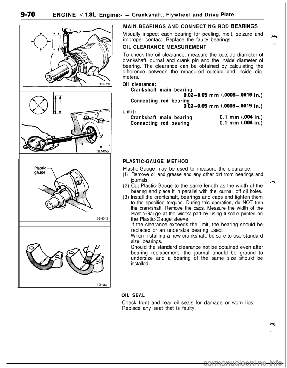
OIL CLEARANCE MEASUREMENTTo check the oil clearance, measure the outside diameter of
crankshaft journal and crank pin and the inside diameter of
bearing. The clearance can be obtained by calculating the
difference between the measured outside and inside dia-
meters.
Oil clearance:
Crankshaft main bearing
0.02-0.05 mm (.OOOS-.0019 in.)
Connecting rod bearing
0.02-0.05 mm (.OOOS-.0019 in.)
Limit:
Crankshaft main bearing0.1 mm (.004 in.)
Connecting rod bearing0.1 mm (.004 in.)
PLASTIC-GAUGE METHODPlastic-Gauge may be used to measure the clearance.
(1)Remove oil and grease and any other dirt from bearings and
journals.(2) Cut Plastic-Gauge to the same length as the width of the
bearing and place it in parallel with the journal, off oil holes.(3) Install the crankshaft, bearings and caps and tighten them
to the specified torques. During this operation, do NOT turn
the crankshaft. Remove the caps. Measure the width of the
Plastic-Gauge at the widest part by using
a scale printed onthe Plastic-Gauge sleeve.
If the clearance exceeds the limit, the bearing should be
replaced or an undersize bearing used.
When installing a new crankshaft, be sure to use standard
size bearings.Should the standard clearance not be obtained even after
bearing replacement, the journal should be ground to
undersize and a bearing of the same size should be
installed.
OIL SEALCheck front and rear oil seals for damage or worn lips.
Replace any seat that is faulty.
Page 357 of 1216
ENGINE <1.8L Engine> - Cylinder Block9-73
lIf cylinder top ridge is worn in stages, smooth out with a
ridge reamer.
l Oversize pistons are available in four sizes.
Piston oversizes and marks:0.25 mm
(.OlO in.) OS. 0.25
0.50 mm
(.020 in.) O.S. 0.50
0.75 mm
(.030 in.) O.S. 0.75
1
.OO mm (.039 in.) O.S. 1.00
lTo rebore the cylinder to an oversize, keep the specified
clearance between the oversize piston and the bore, and
make sure that all pistons used are of the same oversize.
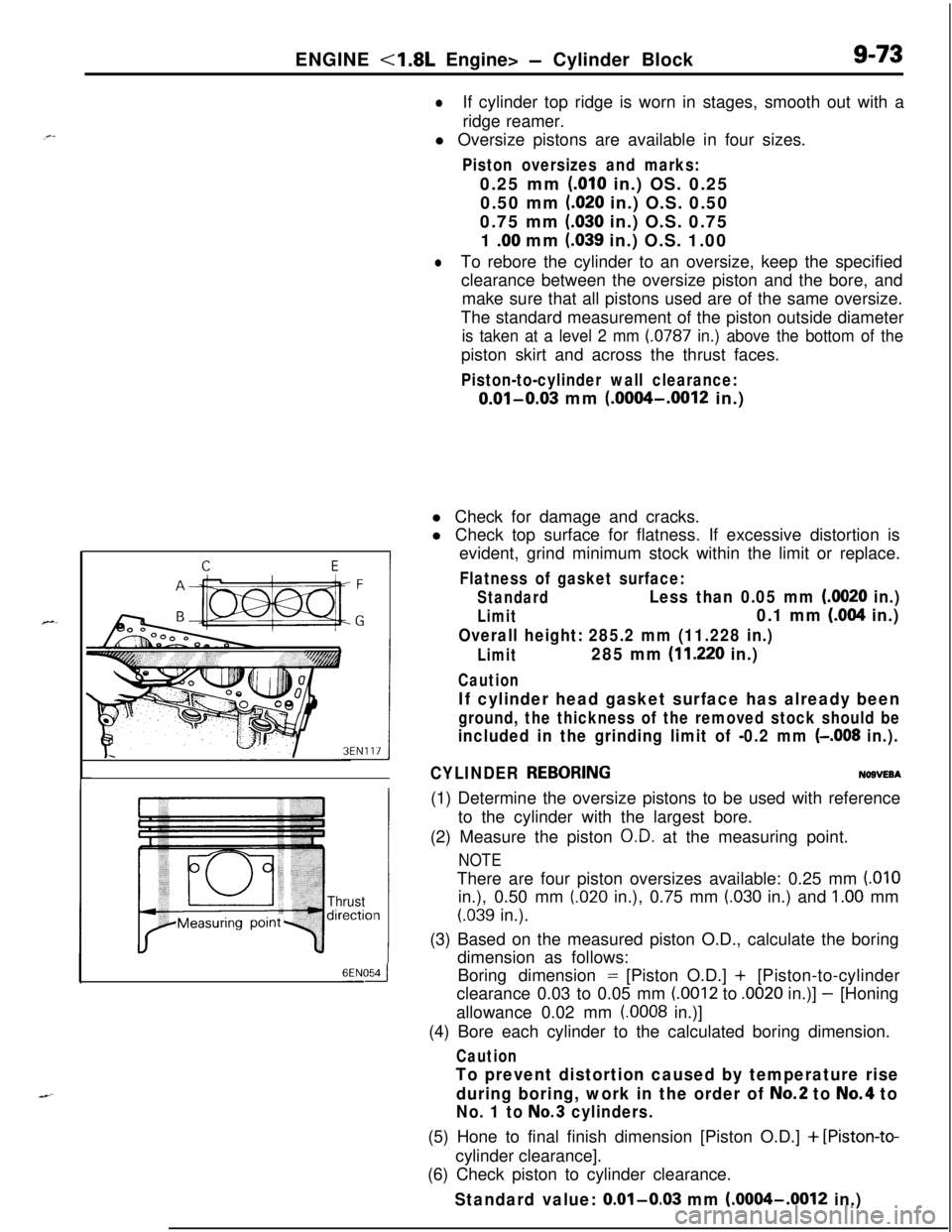
The standard measurement of the piston outside diameter
is taken at a level 2 mm (0787 in.) above the bottom of thepiston skirt and across the thrust faces.
Piston-to-cylinder wall clearance:
0.01-0.03 mm (.0004-.0012 in.)
Thrustdirectiol
6ENOdl Check for damage and cracks.
l Check top surface for flatness. If excessive distortion is
evident, grind minimum stock within the limit or replace.
Flatness of gasket surface:
StandardLess than 0.05 mm (0020 in.)
Limit0.1 mm (.004 in.)
Overall height: 285.2 mm (11.228 in.)
Limit285 mm (11.220 in.)
Caution
If cylinder head gasket surface has already been
ground, the thickness of the removed stock should be
included in the grinding limit of -0.2 mm (-.008 in.).
CYLINDER
REBORINGNOBVEBA(1) Determine the oversize pistons to be used with reference
to the cylinder with the largest bore.
(2) Measure the piston
O.D. at the measuring point.
NOTEThere are four piston oversizes available: 0.25 mm
(.OlOin.), 0.50 mm
(.020 in.), 0.75 mm (.030 in.) and 1.00 mm
(.039 in.).
(3) Based on the measured piston O.D., calculate the boring
dimension as follows:
Boring dimension = [Piston O.D.] + [Piston-to-cylinder
clearance 0.03 to 0.05 mm
(.0012 to .0020 in.)] - [Honing
allowance 0.02 mm
(.0008 in.)]
(4) Bore each cylinder to the calculated boring dimension.
Caution
To prevent distortion caused by temperature rise
during boring, work in the order of
No.2 to No.4 to
No. 1 to No.3 cylinders.(5) Hone to final finish dimension [Piston O.D.]
+ [Piston-to-cylinder clearance].
(6) Check piston to cylinder clearance.
Standard value: 0.01-0.03 mm (.0004-.0012 in.)
Page 1044 of 1216
22-6WHEELS AND TIRES - Wheel and Tire
INSTRUCTIONS FOR ALUMINUM TYPE
WHEELSUzzGfM
1. Aluminum is vulnerable to alkalies. If a vehicle
washing detergent has been used, or salt from
sea water or road chemicals has adhered, washthe vehicle as soon as possible. After washing
the vehicle, apply body or wheel wax to the
aluminum type wheels to prevent corrosion.
2. When cleaning the vehicle with steam, do not
direct steam onto the aluminum type wheels.
When tightening nuts for aluminum type
wheels, particularly observe the following:
(1) Clean the hub surface of aluminum type
wheels.(2) After finger-tightening wheel nuts, tighten
them to specifications.
(3) Do not use an impact wrench or push the
wrench by foot to tighten the wheel nuts.
(4) Do not apply oil to the threaded portions.
INSTRUCTIONS FOR TIRE CHAINS AND
SNOW TIRESNZZGGAA
1.Use tire chains only on front wheels. Do not usetire chains on rear wheels.
2. When using snow tires, use them on all four
wheels for maneuverability and safety.
INSTRUCTIONS FOR COMPACT SPARE
TIRE;c.1. The compact spare tire is designed to. save
space in the luggage compartment, and its
L’lighter weight makes it easier to use if a fiat tire
occurs.
2.The following instructions for the compact sparetire should be observed.
(1) Check the inflation pressure after installing
the spare, and adjust to the specified pres-
sure.(2) Avoid driving through automatic car washes
and over obstacles that could possibly dam-
age the vehicle’s undercarriage. Because
the tire is smaller than the original tire, car
ground clearance is slightly reduced.
(3) The compact spare tire should not be used
on any other wheels, nor should standard
tires, snow tires, wheel covers or trim rings
be used with the compact spare wheel. If
such use is attempted, damage to these
items or other vehicle components may
occur.