window MITSUBISHI ECLIPSE 1991 Owner's Manual
[x] Cancel search | Manufacturer: MITSUBISHI, Model Year: 1991, Model line: ECLIPSE, Model: MITSUBISHI ECLIPSE 1991Pages: 1216, PDF Size: 67.42 MB
Page 1113 of 1216

BODY - Power Window/Door Handle and Latch23-69
I-
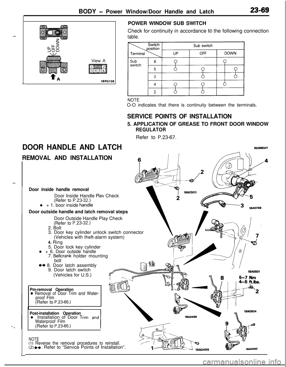
DOOR HANDLE AND LATCHPOWER WINDOW SUB SWITCH
Check for continuity in accordance
10 the following connection
table.
NOTEO-O indicates that there is continuity between the terminals.
SERVICE POINTS OF INSTALLATION5. APPLICATION OF GREASE TO FRONT DOOR WINDOW
REGULATORRefer to
P.23-67.
N23MDAY
REMOVAL AND INSTALLATIONc
Door inside handle removalDoor Inside Handle
Plav Check(Refer to P.23-32.1l + 1. boor inside
handieDoor outside handle and latch removal steps
LDoor Outside Handle Play Check
(Refer to P.23-32.)2. Bolt
3. Door key cylinder unlock switch connector
(Vehicles with theft-alarm system)
4. Ring
5. Door lock key cylinder
l + 6. Door outside handle7. Bellcrank holder mountingbolt
.a 8. Door latch assembly
9. Door latch switch
(Vehicles for U.S.)
Pm-removal Operation0 Removal of Door Trim and Water-
proof Film(Refer to
P.23-65.)
Post-installation Operationl Installation of Door Trim and
1
Waterproof Film(Refer to P.23-65.)
NOTE(I)
Reverse the removal procedures to reinstall.‘/(2) *+ : Refer to “Service Points of Installation”.1m
Page 1115 of 1216

BODY - Central Door Locking System/Door Runchannel23-71View A
18A0064-
L
DOOR RUNCHANNEL
REMOVAL AND INSTALLATION
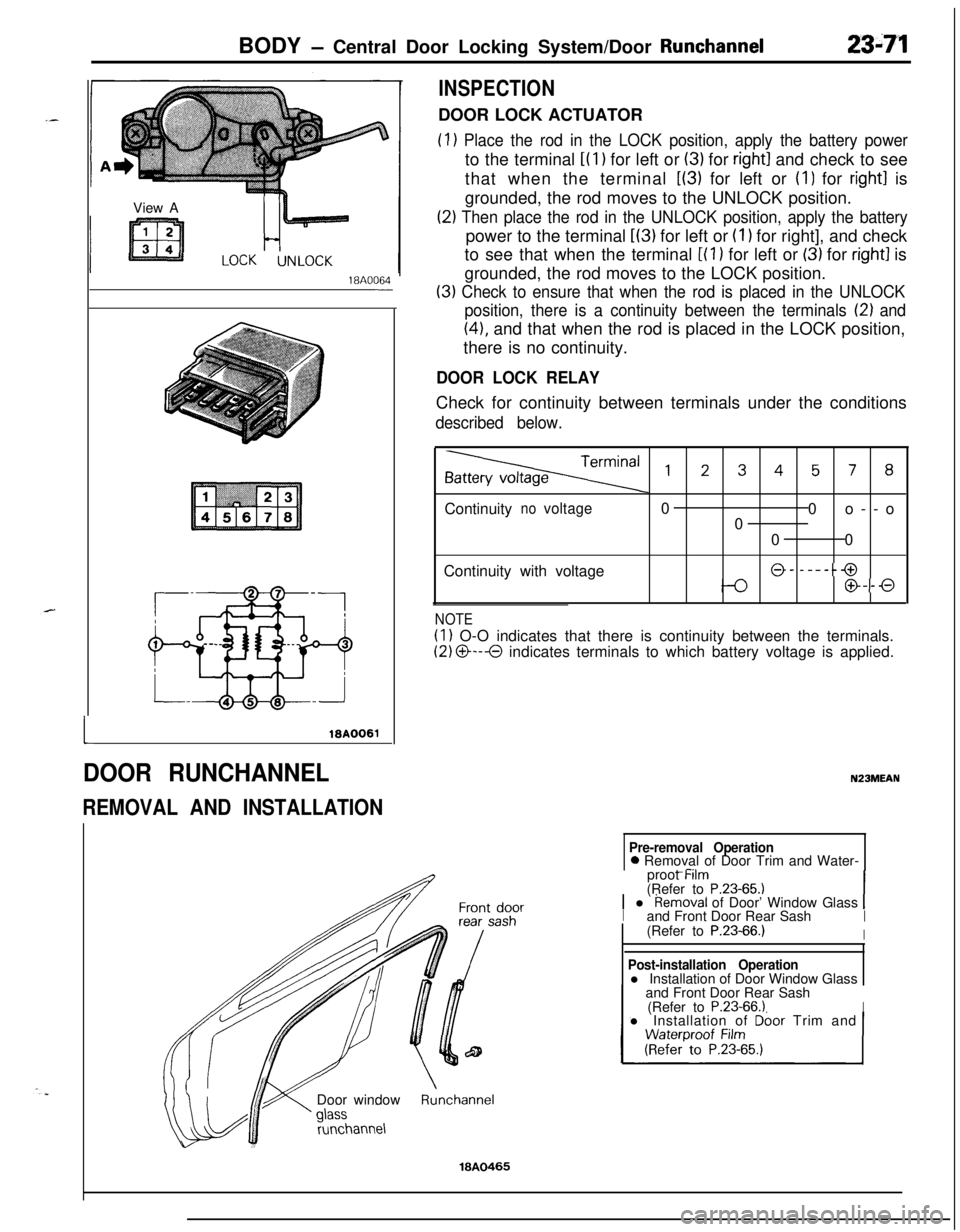
INSPECTIONDOOR LOCK ACTUATOR
(1) Place the rod in the LOCK position, apply the battery powerto the terminal
i(l) for left or (3) for right1 and check to see
that when the terminal
L(3) for left or (I) for right1 is
grounded, the rod moves to the UNLOCK position.
(2) Then place the rod in the UNLOCK position, apply the batterypower to the terminal
L(3) for left or (I 1 for right], and check
to see that when the terminal
[(l ) for left or (3) for right1 is
grounded, the rod moves to the LOCK position.
(3) Check to ensure that when the rod is placed in the UNLOCK
position, there is a continuity between the terminals
12) and
(41, and that when the rod is placed in the LOCK position,
there is no continuity.
DOOR LOCK RELAYCheck for continuity between terminals under the conditions
described below.
,2345, 8Continuity
novoltage0
0o--o
0
00
Continuity with voltage
@- -----@
@--0
NOTE
(1) O-O indicates that there is continuity between the terminals.
(2) O---O indicates terminals to which battery voltage is applied.
N23MEAN
Pre-removal Operation0 Removal of Door Trim and Water-
_ -..proot Mm
(Refer to
P.23-65.11 l Removal of Door’ Window Glass 1Iand Front Door Rear SashI(Refer to P.23-66.)IDoor window
runchannel
Post-installation Operationl Installation of Door Window Glass
and Front Door Rear Sash
(Refer to
P.23-66.1Il Installation of Dbor Trim and
Runchannel
18A0465
Page 1126 of 1216

23-82BODY - Instrument Panel
9N23
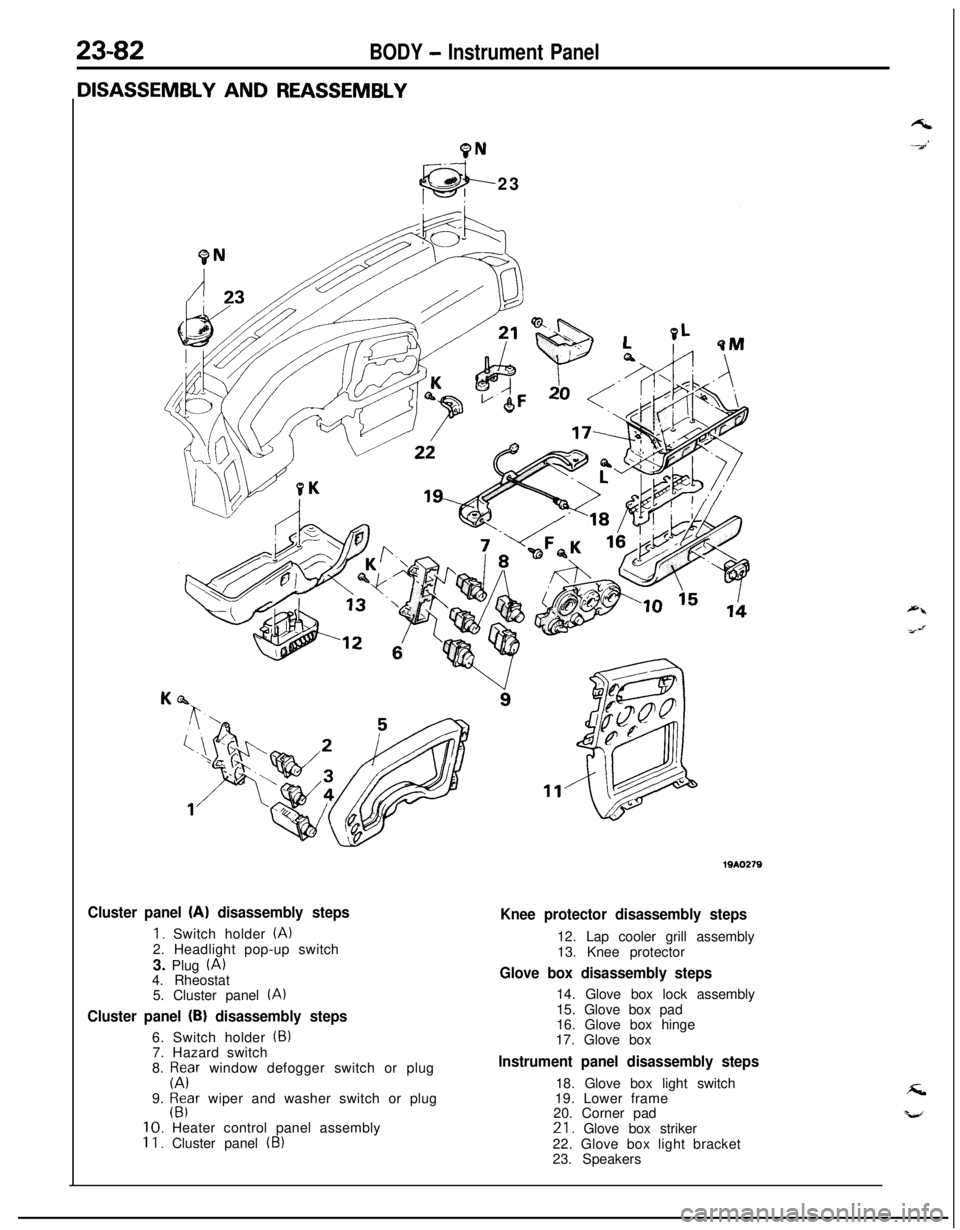
Cluster panel (A) disassembly steps
1. Switch holder (A)2. Headlight pop-up switch
3. Plug
(A)4. Rheostat
5. Cluster panel
(A)
Cluster panel (B) disassembly steps6. Switch holder
(5)7. Hazard switch
8.
p;Fr window defogger switch or plug
9.
$far wiper and washer switch or plug10. Heater control panel assembly
II. Cluster panel (B)
Knee protector disassembly steps12. Lap cooler grill assembly
13. Knee protector
Glove box disassembly steps14. Glove box lock assembly
15. Glove box pad
16. Glove box hinge
17. Glove box
Instrument panel disassembly steps18. Glove box light switch
19. Lower frame
20. Corner pad21. Glove box striker
22. Glove box light bracket
23. Speakers
Page 1160 of 1216

24-16 HEATERS AND AIR CONDITIONING - Service Adjustment Procedures
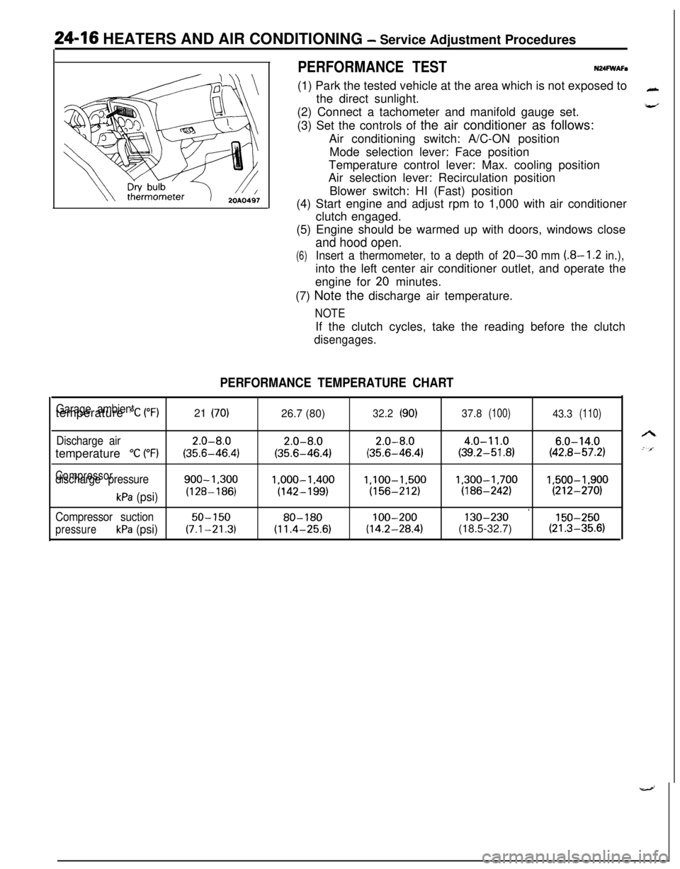
PERFORMANCE TESTN24FWAFa(1) Park the tested vehicle at the area which is not exposed to
the direct sunlight.
(2) Connect a tachometer and manifold gauge set.
(3) Set the controls of the air conditioner as follows:
Air conditioning switch: A/C-ON position
Mode selection lever: Face position
Temperature control lever: Max. cooling position
Air selection lever: Recirculation position
Blower switch: HI (Fast) position
(4) Start engine and adjust rpm to 1,000 with air conditioner
clutch engaged.
(5) Engine should be warmed up with doors, windows close
and hood open.
(6)Insert a thermometer, to a depth of 20-30 mm (8-I .2 in.),into the left center air conditioner outlet, and operate the
engine for
20 minutes.
(7) Note the discharge air temperature.
NOTEIf the clutch cycles, take the reading before the clutch
disengages.
PERFORMANCE TEMPERATURE CHART
Garage ambienttemperature “C (“F)21 (70)26.7 (80)32.2(90)37.8(100)43.3(110)
Discharge air2.0-8.02.0-8.02.0-8.04.0-11.06.0-14.0temperature
“C (“F)(35.6-46.4)(35.6-46.4)(35.6-46.4)(39.2-51.8)(42.8-57.2)
Compressordischarge pressure900-1.3001.000-1.400l,lOO-1,5001,300-1,7001,500-1,900
kPa (psi)(128-186)(142-199)(156-212)(186-242)(212-270)
’Compressor suction50-15080-180100-200130-230150-250
pressurekPa (psi)(7.1-21.3)(11.4-25.6)(14.2-28.4)(18.5-32.7)(21.3-35.6)
Page 1162 of 1216

24-18 HEATERS AND AIR CONDITIONING - Service Adjustment Procedures
(5) Screw a can of R-12 to the opened manifold valve. Be sure
gasket is in place and in good condition. Tighten refrigerantcan and manifold locking nut to insure a good seal. Do not
overtighten 8 to
11 Nm (6 to 8 ft.lbs.) is sufficient if gasket
is in good condition.
(6) Turn manifold valve (above the refrigerant can) completely
clockwise to puncture the can. This closes the valve and
seals the refrigerant in the can.
Caution
Never heat small cans of refrigerant over
40°C (104°F)as they may explode.
(7) Place the refrigerant in a large pan of water heated to 52°C
(104°F). Place pan of water containing the refrigerant can
on an accurate scale so the amount of refrigerant added
can be weighed. Open the refrigerant manifold valve.
(8) Purge all air from test hoses. Air in the system will be
trapped in the condenser causing abnormally high dis-
charge pressures and interfering with condensing of the
refrigerant.(9) Slightly loosen both test hoses at the gauge set manifold.
Tighten the hoses as soon as the air is purged.
(10)Slightly loosen charging hose connection at gauge set
manifold. This will purge air from the charging hose.
Tighten connection as soon as air is purged.
(I l)With vehicle windows open and hood up, operate engine at1,500 rpm and jump the low pressure switch terminals
located on the receiver drier so the clutch will remain
engaged.
(12)Place air conditioner control on air conditioner and place theblower switch on high.
(13)lf necessary, block the condenser to maintain a discharge
pressure of 1,422 to 1,520
kPa (206 to 220 psi). System
must be charged through the evaporator suction service
ports as follows:
(a) Slowly open the suction service gauge valve.
Meter flow of refrigerant by adjusting, the suciton
service gauge valve so that pressure registered at the
suction service gauge does not exceed 345 kPa (50 psi).Keep refrigerant container upright.
(b) Add refrigerant gas until there is no foam visible at the
sight glass.
Add an additional
170 g (6 oz.)
(c) Close the suction gauge valve.
CautionToo much refrigerant in the system can cause
abnormally high discharge pressures. Care must beused so that the exact recommended amount or
refrigerant is added after foam clears in the sight
glass.(d) Close dispensing manifold valve. Remove test hoses
and adapters from the service ports of compressor,
install protective caps at service ports and reconnect
wiring.(e) Check system performance.
(P.24- 16.)
e
. i”
A
i-4