lock MITSUBISHI ECLIPSE 1991 Service Manual
[x] Cancel search | Manufacturer: MITSUBISHI, Model Year: 1991, Model line: ECLIPSE, Model: MITSUBISHI ECLIPSE 1991Pages: 1216, PDF Size: 67.42 MB
Page 1165 of 1216

i
HEATERS AND AIR CONDITIONING - Service Adjustment Procedures 24-21Hot water40°C (104°F)
1467CHARGING SYSTEM
The refrigerant system must have been evacuated using the
previous procedure before charging.
Charge using only R-l 2 refrigerant.
R-12 is available in bulk
tanks or small cans. Follow the safety precautions for handling
R-12 as listed in this group.
Charging with Small Cans
When using disposable cans of this type, follow carefully the
can manufacturers instructions.
Caution
Never use these cans to charge into the high pressure side
of the system (compressor discharge port) or into a systemthat is at high temperature, because the high system
pressures could be transferred into the charging can
causing it to explode.
Keep the refrigerant manifold valves capped when not in use.
Keep a supply of extra refrigerant-can-to-refrigerant-manifold
gaskets on hand so that gaskets can be replaced periodically.
This will insure a good seal without excessive tightening of thecan or the manifold nuts.
(1) Attach center hose from manifold gauge set to refrigerant
dispensing manifold. Turn refrigerant manifold valves com-pletely anticlockwise so they are fully open.
Remove protective caps from refrigerant manifold.
(2) Screw refrigerant cans into manifold. Be sure
manifold-to-can gasket is in place and in good condition. Tighten can
and manifold nuts to 8 to 11 Nm (6 to 8
ft.lbs.).(3) Turn refrigerant manifold valves completely clockwise to
puncture the cans and close the manifold valves.
(4) Purge the air from the charging line by loosening the
charging hose at the gauge set manifold and turning one ofthe refrigerant valves anticlockwise to release refrigerant.
When the refrigerant gas starts escaping from the loose
connection, re-tighten the hose.
Caution
Never heat small refrigerant cans over
40°C (104°F) as
they may explode.
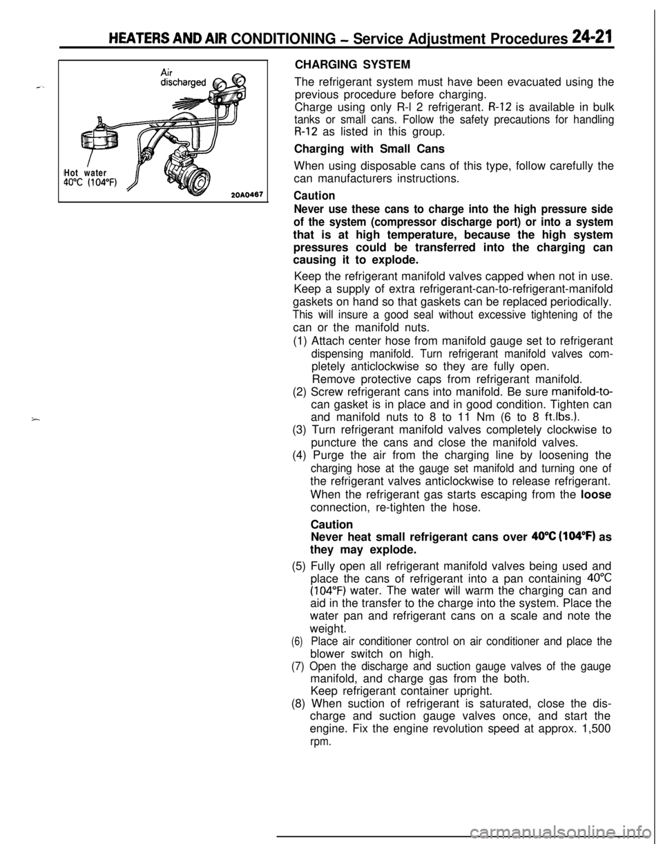
(5) Fully open all refrigerant manifold valves being used and
place the cans of refrigerant into a pan containing
40°C
(104°F) water. The water will warm the charging can and
aid in the transfer to the charge into the system. Place the
water pan and refrigerant cans on a scale and note the
weight.
(6)Place air conditioner control on air conditioner and place theblower switch on high.
(7) Open the discharge and suction gauge valves of the gaugemanifold, and charge gas from the both.
Keep refrigerant container upright.
(8) When suction of refrigerant is saturated, close the dis-
charge and suction gauge valves once, and start the
engine. Fix the engine revolution speed at approx. 1,500
rpm.
Page 1170 of 1216

24-26HEATERS AND AIR CONDITIONING - Heater Control AssemblyHEATER CONTROL ASSEMBLY
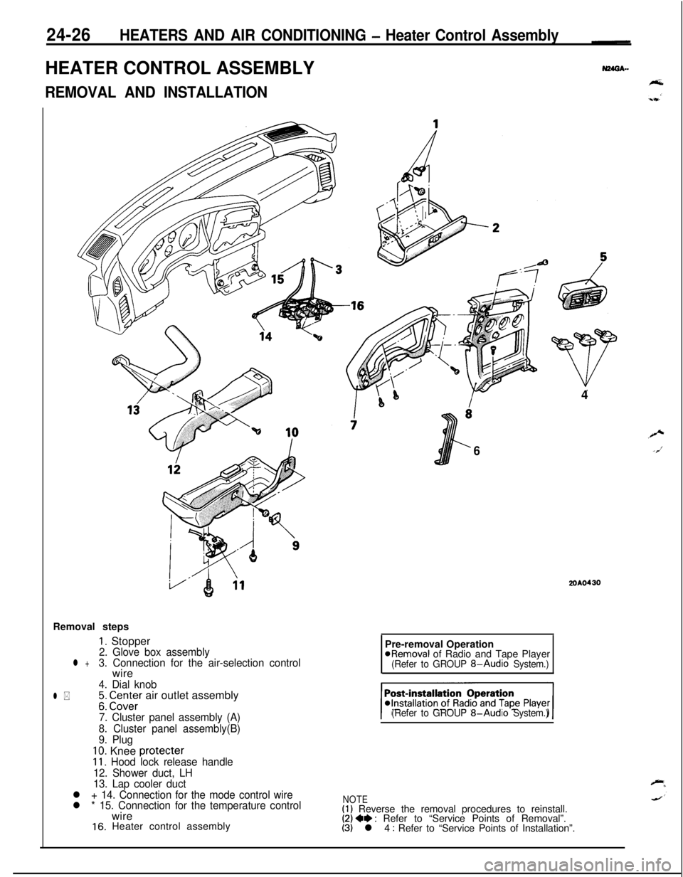
REMOVAL AND INSTALLATIONRemoval steps
1. Stopper2. Glove box assemblyl +3. Connection for the air-selection controlwire
4. Dial knob
l *;: CI.Z;Er air outlet assembly
7. Cluster panel assembly (A)
8. Cluster panel assembly(B)
9. Plug
10. Knee protecter11. Hood lock release handle
12. Shower duct, LH
13. Lap cooler duct
l + 14. Connection for the mode control wire
l * 15. Connection for the temperature controlwire
16. Heater control assembly4
6
2OAO430Pre-removal Operation
@Removal of Radio and Tape Player(Refer to GROUP 8-Audio System.)
(Refer to GROUP
8-Audio System.)
NOTE(1) Reverse the removal procedures to reinstall.(2) 4e : Refer to “Service Points of Removal”.(3) l 4 : Refer to “Service Points of Installation”.
Page 1193 of 1216

HEATERS AND AIR CONDITIONING- Ventilators (Instrument Panel)24-49
16
VENTILATORS (INSTRUMENT PANEL)
I- -REMOVAL AND INSTALLATION
,’ !‘\
19< !.an
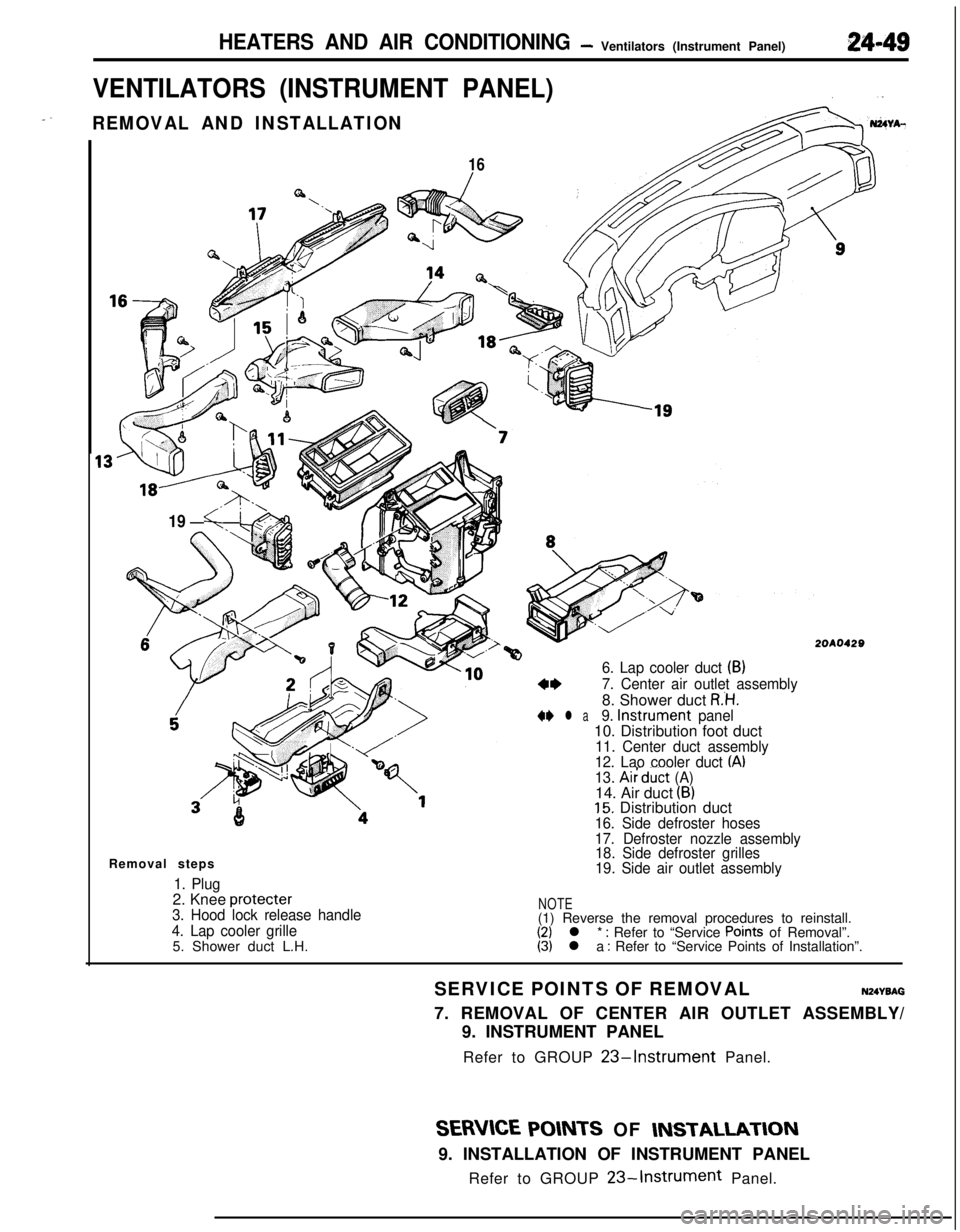
6. Lap cooler duct (B)
2OAO420
a*7. Center air outlet assembly8. Shower duct
R’H.+* l a9. Instrument panel10. Distribution foot duct
11. Center duct assembly
12. Lao cooler duct IA)13. AiFduct (A)14. Air duct (B)15. Distribution duct16. Side defroster hoses
17. Defroster nozzle assembly
18. Side defroster grilles
19. Side air outlet assemblyRemoval steps
1. Plug2. Knee protecter
3. Hood lock release handle
4. Lap cooler grilleNOTE(1) Reverse the removal procedures to reinstall.
(2) l * : Refer to “Service Points of Removal”.
5. Shower duct L.H.(3) l a : Refer to “Service Points of Installation”.
SERVICE POINTS OF REMOVAL
NZNBAG7. REMOVAL OF CENTER AIR OUTLET ASSEMBLY/
9. INSTRUMENT PANEL
Refer to GROUP
23-Instrument Panel.
SERVICE POINTS OF INSTAUAT-ION9. INSTALLATION OF INSTRUMENT PANEL
Refer to GROUP
23-Instrument Panel.