length MITSUBISHI ECLIPSE 1991 Owner's Guide
[x] Cancel search | Manufacturer: MITSUBISHI, Model Year: 1991, Model line: ECLIPSE, Model: MITSUBISHI ECLIPSE 1991Pages: 1216, PDF Size: 67.42 MB
Page 612 of 1216
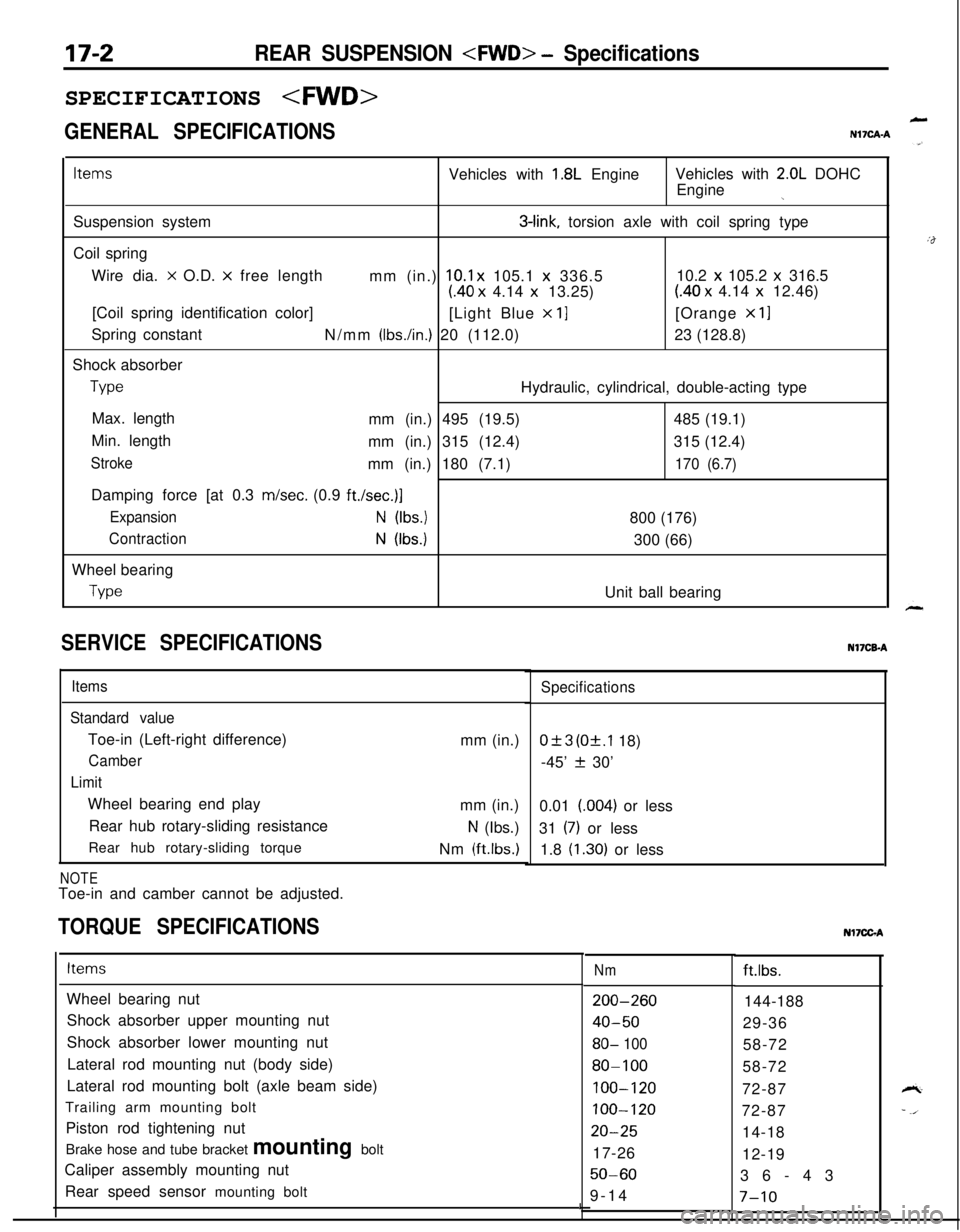
17-2REAR SUSPENSION
GENERAL SPECIFICATIONS
LN17CAA
ItemsVehicles with 1.8L EngineVehicles with 2.0L DOHC
Engine
jSuspension system
3-link, torsion axle with coil spring type
Coil spring
Wire dia.
x O.D. x free length
mm (in.) 10.1 x 105.1 x 336.510.2 x 105.2 x 316.5
(40 x 4.14 x 13.25)(40 x 4.14 x 12.46)
[Coil spring identification color]
[Light Blue
x 11[Orange x 11Spring constant
N/mm
(Ibs./in.) 20 (112.0)23 (128.8)
Shock absorber
TypeHydraulic, cylindrical, double-acting type
Max. length
mm (in.) 495 (19.5)485 (19.1)
Min. length
mm (in.) 315 (12.4)315 (12.4)
Strokemm (in.) 180 (7.1)170 (6.7)Damping force [at 0.3 m/set. (0.9
ft./set.)]
ExpansionN (Ibs.)800 (176)
ContractionN (Ibs.)300 (66)
Wheel bearing
TypeUnit ball bearing
SERVICE SPECIFICATIONS
Items
Standard valueToe-in (Left-right difference)
Camber
LimitWheel bearing end play
Rear hub rotary-sliding resistance
Rear hub rotary-sliding torque
NOTEToe-in and camber cannot be adjusted.mm (in.)
mm (in.)
N (Ibs.)
Nm
(ftlbs.)
TORQUE SPECIFICATIONS
Specifications
0+3 (Of.1 18)
-45’
f 30’
0.01 (004) or less
31
(7) or less
1.8
(1.30) or lessNI’ICB-A
ItemsNmft.lbs.
Wheel bearing nut
Shock absorber upper mounting nut
Shock absorber lower mounting nut
Lateral rod mounting nut (body side)
Lateral rod mounting bolt (axle beam side)
Trailing arm mounting bolt
Piston rod tightening nut
Brake hose and tube bracket mounting bolt
Caliper assembly mounting nut
Rear speed sensor mounting bolt
200-260
40-50
80- 100
80-100
100-120
100-120
20-2517-26
50-609-14144-188
29-36
58-72
58-72
72-87
72-87
14-18
12-19
36-43
I7-10
Nl7CGA
Page 626 of 1216

17-16REAR SUSPENSION
SPECIFICATIONS
GENERAL SPECIFICATIONSNl’ICA-B jG
ItemsSpecifications
Suspension systemDouble wishbone suspension type
Coil spring
Wire dia. x O.D.
x free lengthmm (in.)11.0 x 106.0 x 332.5 (.43 x 4.17 x 13.1)Coil spring identification colorPurple
x 1Spring constantN/mm
(Ibs./in.) 25.0 (140)
Shock absorber
TypeHydraulic, cylindrical, double-acting type
Max. lengthmm (in.) 568
(22.4)Min. lengthmm (in.) 380
(15.0)
Strokemm (in.) 188 (7.4)
Damping force [at 0.3 m/set. (0.9
ft./set.)]
ExpansionN (Ibs.) 900 (198)
ContractionN (Ibs.) 300 (66)
SERVICE SPECIFICATIONS
Items
Standard value
Toe-in
CamberSpecificationsmm (in.) 3.6+3 (.14f.l18)
-1"33'f30'
Nl7CEB
:&
Page 675 of 1216
--STEERING - Manual Steering Gear Boxm-2.7
13AO175
Grease
136007(1184-186 mm
(7.24-7.32
in.)
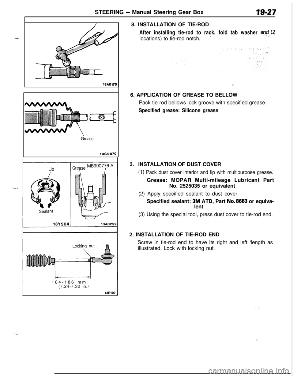
13ElW8. INSTALLATION OF TIE-ROD
After installing tie-rod to rack, fold tab washer
end, (2locations) to tie-rod notch.
’.
.‘6. APPLICATION OF GREASE TO BELLOW
Pack tie rod bellows lock groove with specified grease.
Specified grease: Silicone grease
3.INSTALLATION OF DUST COVER
(1) Pack dust cover interior and lip with multipurpose grease.Grease: MOPAR Multi-mileage Lubricant Part
No. 2525035 or equivalent
(2) Apply specified sealant to dust cover.
Specified sealant:
3M ATD, Part No.8663 or equiva-
lent
(3) Using the special tool, press dust cover to tie-rod end.
2. INSTALLATION OF TIE-ROD END
Screw in tie-rod end to have its right and left ‘length as
illustrated. Lock with locking nut.
Page 686 of 1216
STEERING - Power Steering Gear Box
I-
-l
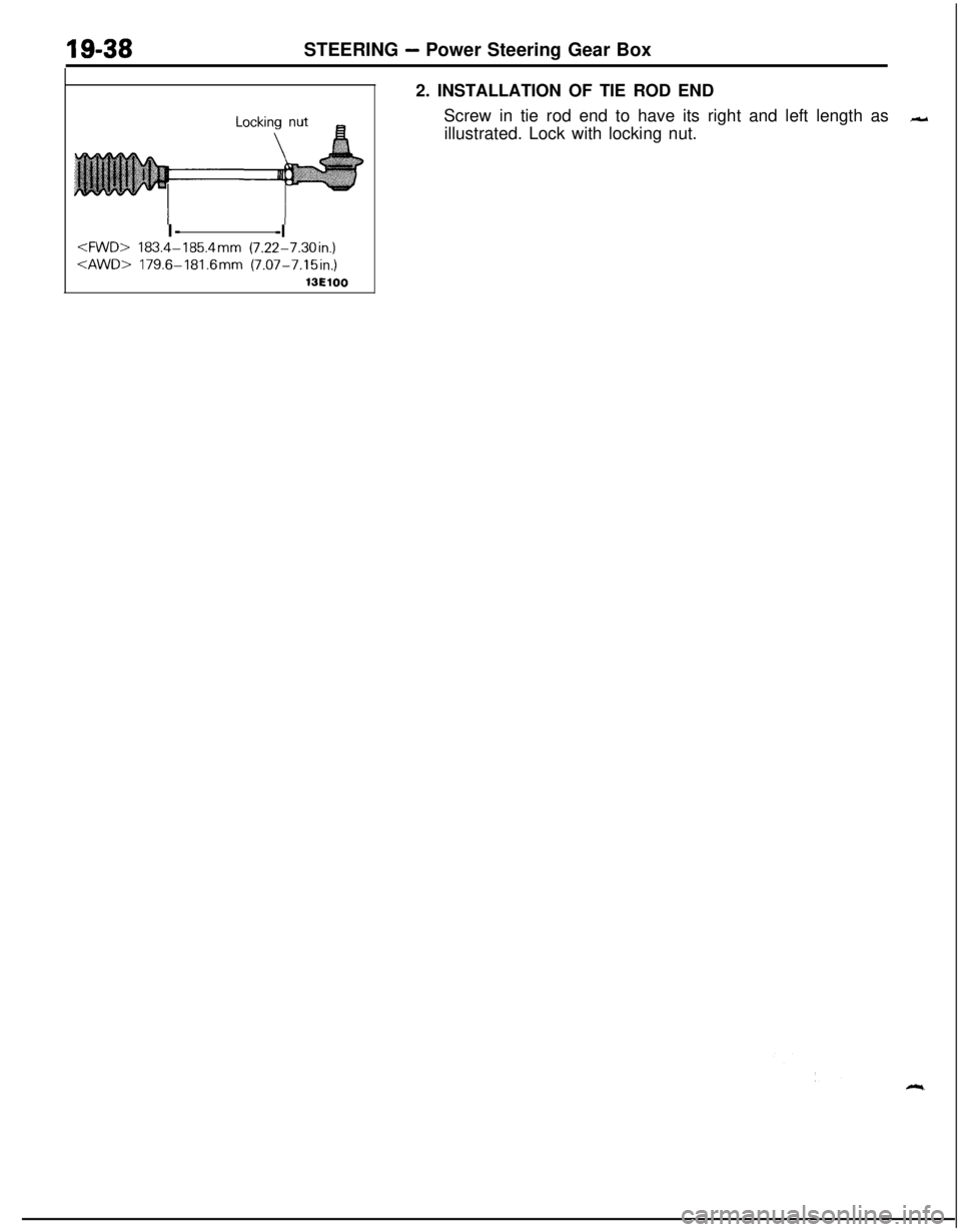
13ElOO2. INSTALLATION OF TIE ROD END
Screw in tie rod end to have its right and left length as
-illustrated. Lock with locking nut.
Page 711 of 1216
MANUAL TRANSAXLE
erShift
lever
09A0159
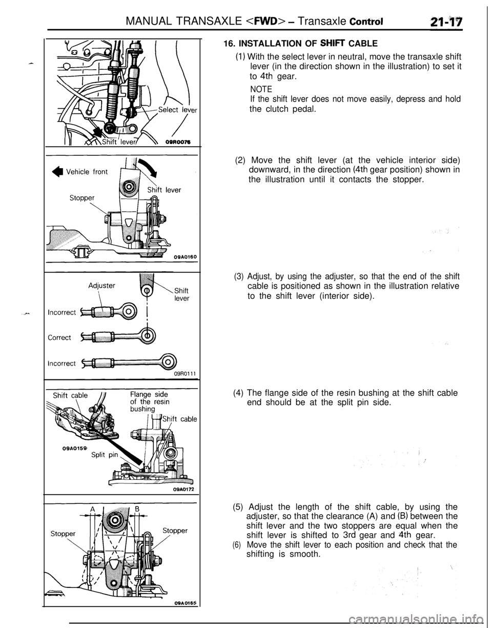
09A016t16. INSTALLATION OF
SHIFT CABLE
(1) With the select lever in neutral, move the transaxle shift
lever (in the direction shown in the illustration) to set it
to
4th gear.
NOTE
If the shift lever does not move easily, depress and holdthe clutch pedal.
(2) Move the shift lever (at the vehicle interior side)
downward, in the direction
(4th gear position) shown in
the illustration until it contacts the stopper.
(3) Adjust, by using the adjuster, so that the end of the shiftcable is positioned as shown in the illustration relative
to the shift lever (interior side).
(4) The flange side of the resin bushing at the shift cable
end should be at the split pin side.
(5) Adjust the length of the shift cable, by using the
adjuster, so that the clearance (A) and
(B) between the
shift lever and the two stoppers are equal when the
shift lever is shifted to
3rd gear and 4th gear.
(6)Move the shift lever to each position and check that theshifting is smooth.
Page 723 of 1216
MANUAL TRANSAXLE
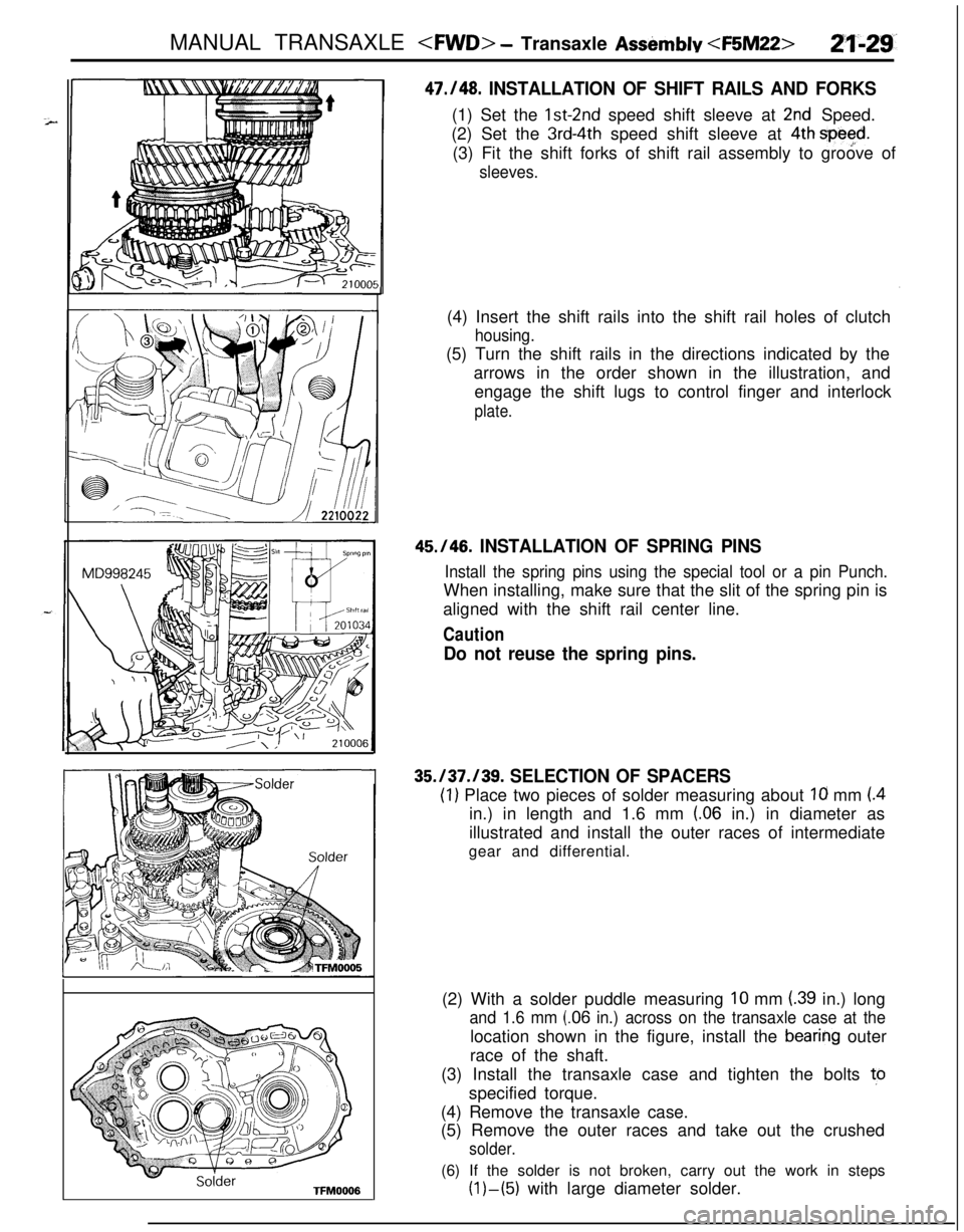
47./48. INSTALLATION OF SHIFT RAILS AND FORKS(1) Set the
lst-2nd speed shift sleeve at 2nd Speed.
(2) Set the
3rd-4th speed shift sleeve at 4th spe$d.(3) Fit the shift forks of shift rail assembly to groove of
sleeves.(4) Insert the shift rails into the shift rail holes of clutch
housing.(5) Turn the shift rails in the directions indicated by the
arrows in the order shown in the illustration, and
engage the shift lugs to control finger and interlock
plate.
45.146. INSTALLATION OF SPRING PINS
Install the spring pins using the special tool or a pin Punch.When installing, make sure that the slit of the spring pin is
aligned with the shift rail center line.
Caution
Do not reuse the spring pins.
35.137.139. SELECTION OF SPACERS
(1) Place two pieces of solder measuring about Ia mm (.4in.) in length and 1.6 mm
(.06 in.) in diameter as
illustrated and install the outer races of intermediate
gear and differential.
(2) With a solder puddle measuring
10 mm (.39 in.) long
and 1.6 mm (.06 in.) across on the transaxle case at thelocation shown in the figure, install the
bearing outer
race of the shaft.
(3) Install the transaxle case and tighten the bolts to
specified torque.
(4) Remove the transaxle case.
(5) Remove the outer races and take out the crushed
solder.(6) If the solder is not broken, carry out the work in steps
(l)-(5) with large diameter solder.
Page 733 of 1216
MANUAL TRANSAXLE
/Shift rail
11-t201034er
2150008
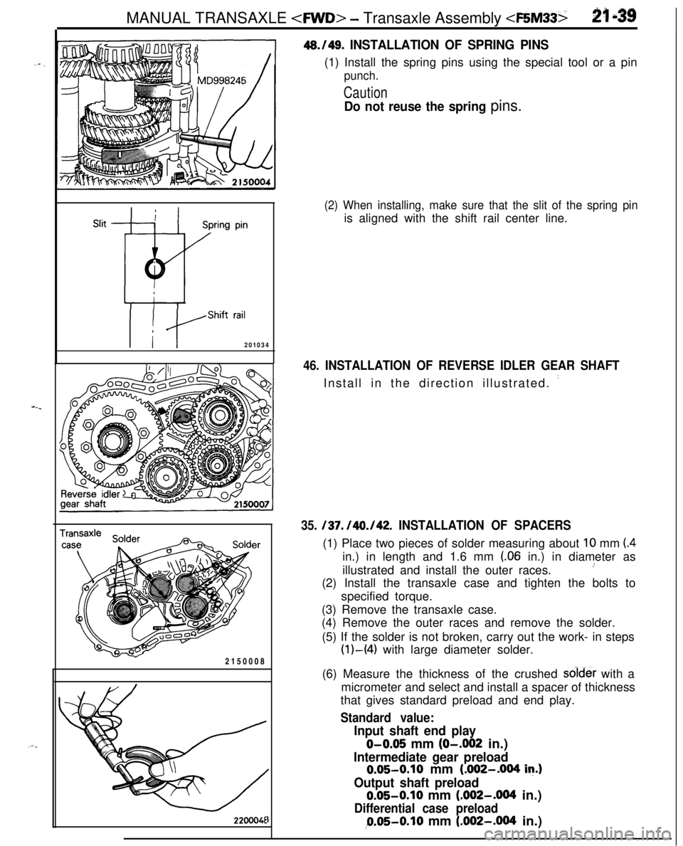
220004E46./49.
INSTALLATION OF SPRING PINS(1) Install the spring pins using the special tool or a pin
punch.
Caution
Do not reuse the spring pins.
(2) When installing, make sure that the slit of the spring pinis aligned with the shift rail center line.
46. INSTALLATION OF REVERSE IDLER GEAR SHAFTInstall in the direction illustrated.
’
35. /37. /40./42. INSTALLATION OF SPACERS(1) Place two pieces of solder measuring about
10 mm (4in.) in length and 1.6 mm
(.06 in.) in diameter as
illustrated and install the outer races.
’(2) Install the transaxle case and tighten the bolts to
specified torque.
(3) Remove the transaxle case.
(4) Remove the outer races and remove the solder.
(5) If the solder is not broken, carry out the work- in steps
(l)-(4) with large diameter solder.
(6) Measure the thickness of the crushed soid& with a
micrometer and select and install a spacer of thickness
that gives standard preload and end play.
Standard value:
Input shaft end play
O-0.05 mm (O-.002 in.)
Intermediate gear preload0.05-0.10 mm (.002-.004
in.)
Output shaft preload0.05-0.10 mm (.092-.004 in.)
Differential case preload
9.05-0.10 mm (.002-.004 in.)
Page 854 of 1216
21-160AUTOMATIC TRANSAXLE - Specifidons
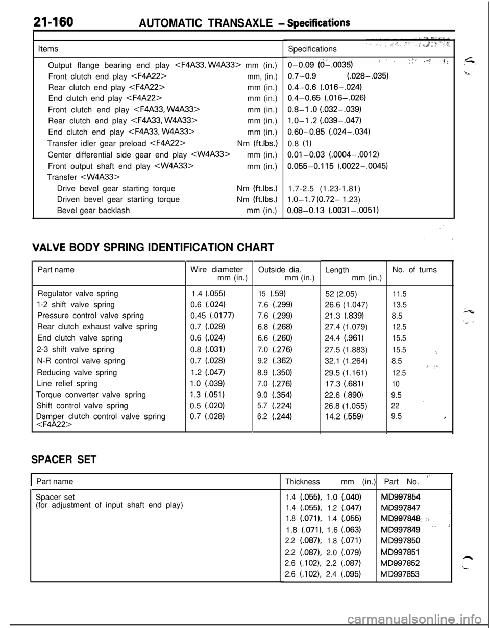
ItemsOutput flange bearing end play
Front clutch end play
End clutch end play
Front clutch end play
Rear clutch end play
End clutch end play
Transfer idler gear preload
Front output shaft end play
Transfer
Driven bevel gear starting torque
Bevel gear backlashNm
(ft.lbs.)Nm
(ft.lbs.)mm (in.)
IALVE BODY SPRING IDENTIFICATION CHARTPart name
Regulator valve spring
l-2 shift valve spring
Pressure control valve spring
Rear clutch exhaust valve spring
End clutch valve spring
2-3 shift valve spring
N-R control valve spring
Reducing valve spring
Line relief spring
Torque converter valve spring
Shift control valve spring
FFyl;;;lutch control valve spring
SPACER SETWire diameter
mm (in.)
1.4 (055)
0.6 (024)
0.45 (0177)
0.7 (028)
0.6
(.024)0.8
(.031)0.7 (028)
1.2 (047)
1.0 l.039)
1.3 (051)
0.5 (020)
0.7
(.028)Outside dia.
mm (in.)
15i.59)
7.6
t.299)
7.6(.299)
6.8(.268)
6.6(260)
7.0(276)
9.2(.362)
8.9(350)
7.0(276)
9.0(.354)
5.7(224)
6.2(.244)
IPart name
Spacer set
(for adjustment of input shaft end play)Specifications
o-0.09 (d-.0035); . ,i f 1, ,i’.” :,li
0.7-0.9 (.028-.035)
0.4-0.6 (.016-.024)
0.4-0.65 (.016-.026)
0.8-I .O (.032-.039)
1.0-I .2 (.039-.047)
0.60-0.85 (.024-.034)
0.8
(1)
0.01-0.03 (.0004-.0012)
0.055-0.115 (.0022-.0045)
1.7-2.5 (1.23-1.81)
1.0-I .7 (0.72- 1.23)
0.08-0.13 (.0031-.0051)
Lengthmm (in.)
52 (2.05)
26.6 (1.047)
21.3
(.839)27.4 (1.079)
24.4
(.961)27.5 (1.883)
32.1 (1.264)
29.5 (1.161)
17.3
(.681)22.6
i.890)26.8 (1.055)
14.2
(.559)No. of turns
11.5
13.5
8.5
12.5
15.5
15.5
‘4
8.5
’-*12.5
10
9.5
’22
9.5I
Thicknessmm (in.) Part No. “’
1.4(055).1.0l.040)MD997854
1.4(.055),
1.2(047)MD997847
’1.8(.071),
1.4l.055)MD997848::!1.8
(.071), 1.6 (.063)fQlD997849 ” .’
2.2(.087),
1.8(.071)MD997850
2.2(.087),2.0(.079)MD997851h2.6(.102),2.2(.087)MD997852“-2.6(.102),2.4i.095)M D997853
Page 948 of 1216
AUTOMATIC TRANSAXLE - Transaxle Assemblv
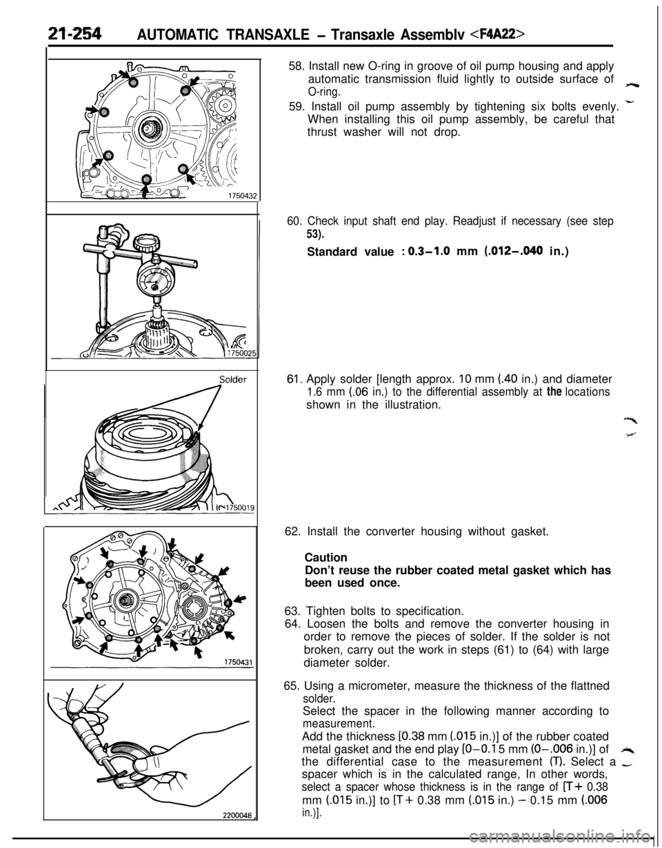
Solder
220004858. Install new O-ring in groove of oil pump housing and apply
automatic transmission fluid lightly to outside surface of
O-ring.e59. Install oil pump assembly by tightening six bolts evenly.
i-When installing this oil pump assembly, be careful that
thrust washer will not drop.
60. Check input shaft end play. Readjust if necessary (see step
53).Standard value
: 0.3-1.0 mm (.012-,040 in.)
61, Apply solder [length approx. 10 mm (40 in.) and diameter
1.6 mm (.06 in.) to the differential assembly at the locationsshown in the illustration.
“I
-4--J62. Install the converter housing without gasket.
Caution
Don’t reuse the rubber coated metal gasket which has
been used once.
63. Tighten bolts to specification.
64. Loosen the bolts and remove the converter housing in
order to remove the pieces of solder. If the solder is not
broken, carry out the work in steps (61) to (64) with large
diameter solder.
65. Using a micrometer, measure the thickness of the flattned
solder.Select the spacer in the following manner according to
measurement.Add the thickness
[0.38 mm (015 in.)] of the rubber coated
metal gasket and the end play
LO-O.1 5 mm (O-.006 in.)] ofi4the differential case to the measurement
(T). Select a -spacer which is in the calculated range, In other words,
select a spacer whose thickness is in the range of n+ 0.38mm
(.015 in.)] to [T+ 0.38 mm (.015 in.) - 0.15 mm (.006
in.)].
Page 973 of 1216
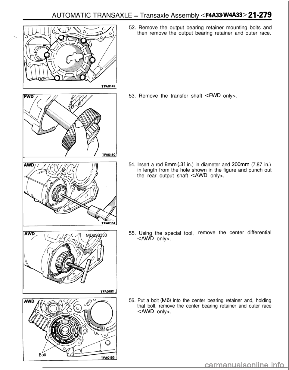
ITFA014952. Remove the output bearing retainer mounting bolts and
then remove the output bearing retainer and outer race.
// TFAOlSOl53. Remove the transfer shaft
54. Insert a rod 8mm (.31 in.) in diameter and 200mm (7.87 in.)in length from the hole shown in the figure and punch out
the rear output shaft
- Transaxle Assembly
TFA0152 .j55. Using the special tool,remove the center differential
56. Put a bolt (M6) into the center bearing retainer and, holding
that bolt, remove the center bearing retainer and outer race