length MITSUBISHI ECLIPSE 1991 User Guide
[x] Cancel search | Manufacturer: MITSUBISHI, Model Year: 1991, Model line: ECLIPSE, Model: MITSUBISHI ECLIPSE 1991Pages: 1216, PDF Size: 67.42 MB
Page 84 of 1216
2-36FRONT SUSPENSION - Lower Arm
Lips
/IDust
cover
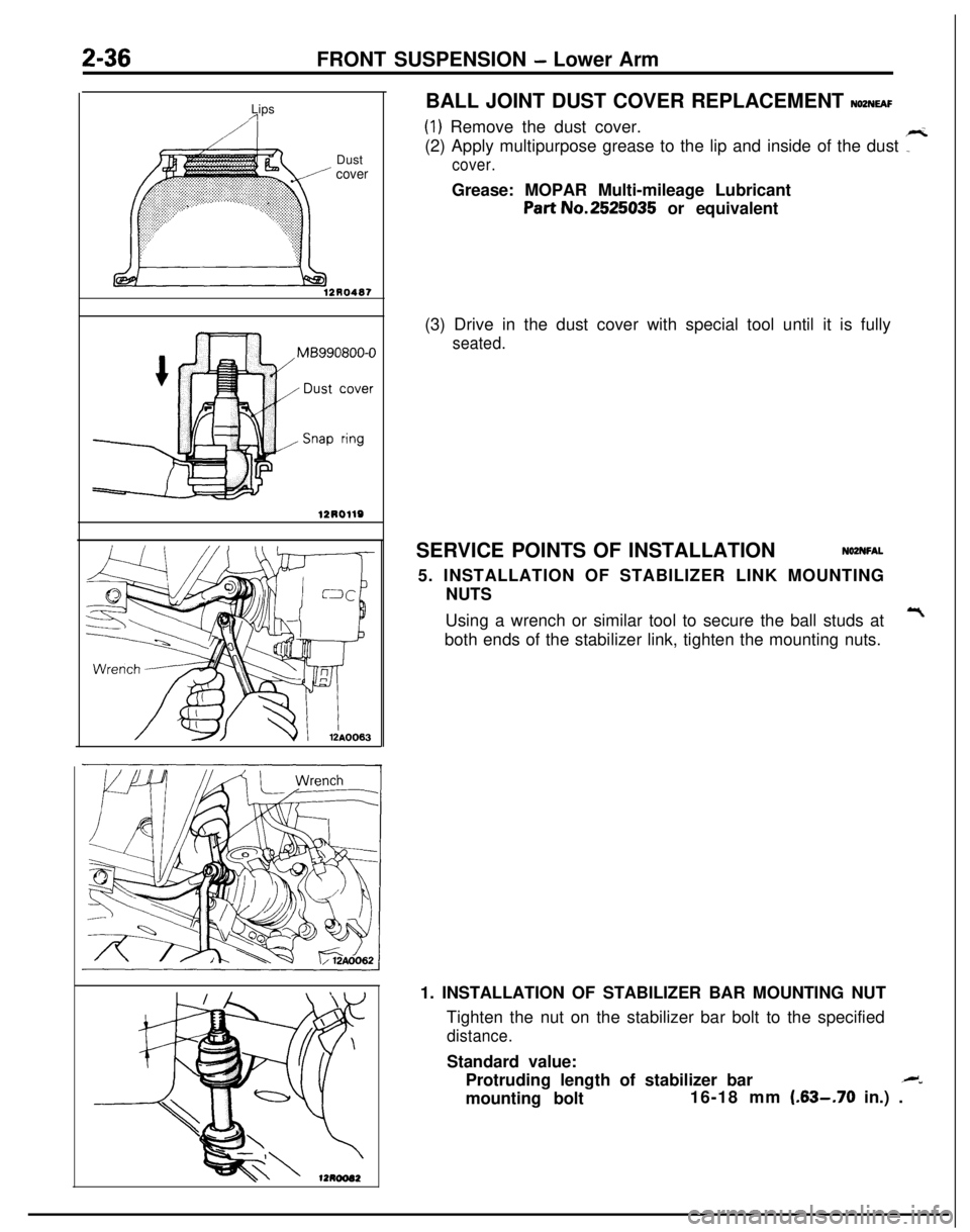
12R0487BALL JOINT DUST COVER REPLACEMENT
NOZNEAF
(1) Remove the dust cover.
(2) Apply multipurpose grease to the lip and inside of the dust
7
cover.Grease: MOPAR Multi-mileage Lubricant
Part No.2525035 or equivalent
(3) Drive in the dust cover with special tool until it is fully
seated.SERVICE POINTS OF INSTALLATION
NOZNFAL5. INSTALLATION OF STABILIZER LINK MOUNTING
NUTS
Using a wrench or similar tool to secure the ball studs at
Tboth ends of the stabilizer link, tighten the mounting nuts.
1. INSTALLATION OF STABILIZER BAR MOUNTING NUT
Tighten the nut on the stabilizer bar bolt to the specified
distance.Standard value:
Protruding length of stabilizer bar
.M”mounting bolt16-18 mm
(.63-.70 in.) .
Page 89 of 1216
FRONT SUSPENSION - Stabilizer Bar241
3 *!-Marking
A I I\/\ \lZAOOOESERVICE POINTS OF INSTALLATION
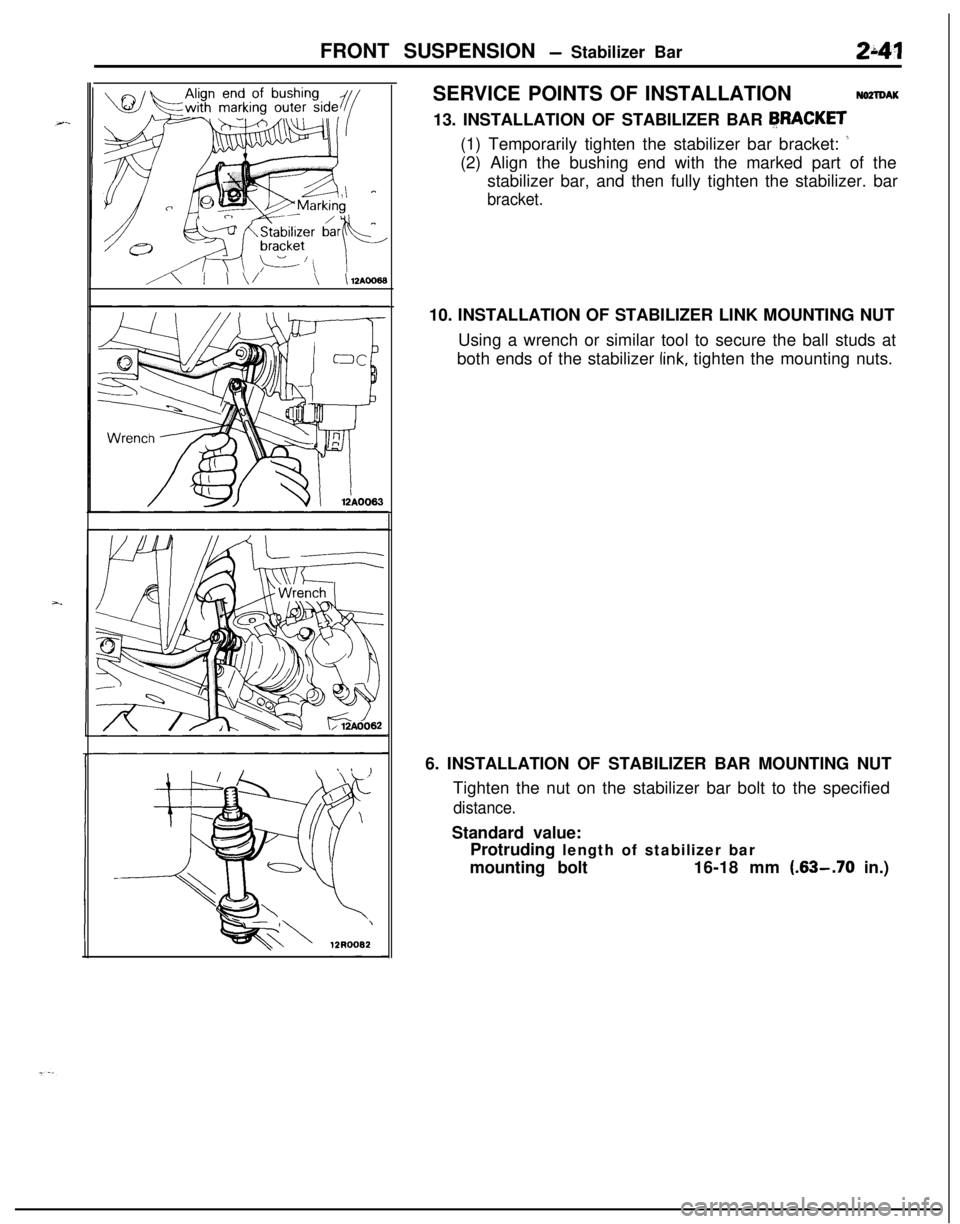
NO2lDAK13. INSTALLATION OF STABILIZER BAR
FRACKET(1) Temporarily tighten the stabilizer bar bracket:
’(2) Align the bushing end with the marked part of the
stabilizer bar, and then fully tighten the stabilizer. bar
bracket.10. INSTALLATION OF STABILIZER LINK MOUNTING NUT
Using a wrench or similar tool to secure the ball studs at
both ends of the stabilizer
link, tighten the mounting nuts.
6. INSTALLATION OF STABILIZER BAR MOUNTING NUT
Tighten the nut on the stabilizer bar bolt to the specified
distance.Standard value:
Protruding length of stabilizer bar
mounting bolt16-18 mm
(.63-.70 in.)
Page 104 of 1216
3-2REAR AXLE - Specifications
SPECIFICATIONS
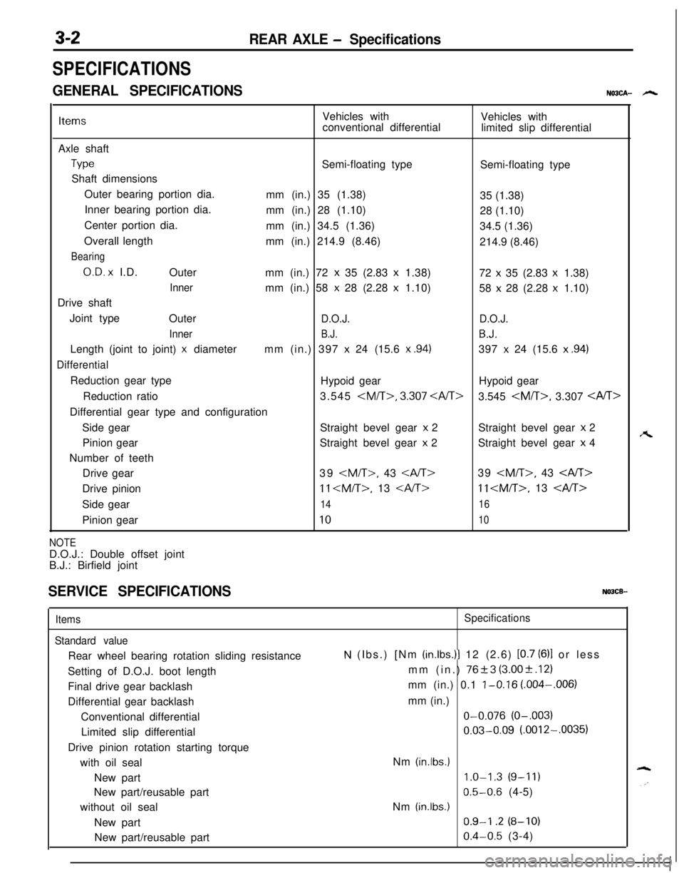
GENERAL SPECIFICATIONSNO3CA- h
ItemsVehicles with
Vehicles with
conventional differential
limited slip differential
Axle shaft
TypeSemi-floating type
Semi-floating type
Shaft dimensions
Outer bearing portion dia.
mm (in.) 35 (1.38)
35 (1.38)
Inner bearing portion dia.
mm (in.) 28 (1.10)
28 (1.10)
Center portion dia.
mm (in.) 34.5 (1.36)
34.5 (1.36)
Overall length
mm (in.) 214.9 (8.46)
214.9 (8.46)
Bearing
O.D. x I.D.
Outer
mm (in.) 72 x 35 (2.83 x 1.38)
72 x 35 (2.83 x 1.38)
Innermm (in.) 58 x 28 (2.28 x 1.10)
58 x 28 (2.28 x 1.10)
Drive shaft
Joint type
Outer
D.O.J.D.O.J.
Inner
B.J.B.J.Length (joint to joint)
x diametermm (in.) 397 x 24 (15.6 x .94)397 x 24 (15.6 x .94)
DifferentialReduction gear type
Hypoid gearHypoid gear
Reduction ratio3.545
3.545
Side gearStraight bevel gear
x 2Straight bevel gear x 2
Pinion gearStraight bevel gear
x 2Straight bevel gear x 4
Number of teeth
Drive gear39
11
Side gear
1416Pinion gear
1010
NOTED.O.J.: Double offset joint
B.J.: Birfield joint
SERVICE SPECIFICATIONSNOBCB-
Items
Standard valueRear wheel bearing rotation sliding resistance
Setting of D.O.J. boot length
Final drive gear backlash
Differential gear backlash
Conventional differential
Limited slip differential
Drive pinion rotation starting torque
with oil seal
New part
New part/reusable part
without oil seal
New part
New part/reusable partSpecifications
N (Ibs.) [Nm (in.lbs.)l 12 (2.6) [0.7 (6)l or less
mm (in.)
76+3 (3.00+.12)
mm (in.) 0.1
l-0.16 (.004-,006)
mm (in.)O-0.076
(O-.003)
0.03-0.09 (.0012-.0035)
Nm
(in.lbs.)
1.0-1.3 (9-11)
0.5-0.6 (4-5)
Nm
(in.lbs.)
0.9-I .2 (8-10)
0.4-0.5 (3-4)
A
Page 117 of 1216
REAR AXLE - Drive Shaft
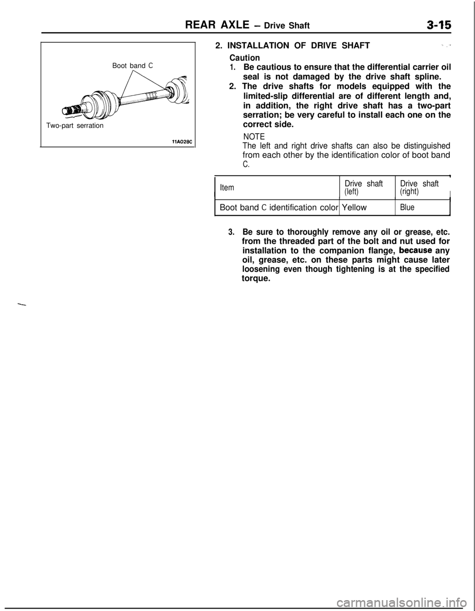
Boot band
CTwo-part serration
llA02802. INSTALLATION OF DRIVE SHAFT
I_ ,T
Caution
1.Be cautious to ensure that the differential carrier oil
seal is not damaged by the drive shaft spline.
2. The drive shafts for models equipped with the
limited-slip differential are of different length and,
in addition, the right drive shaft has a two-part
serration; be very careful to install each one on the
correct side.
NOTE
The left and right drive shafts can also be distinguishedfrom each other by the identification color of boot band
C.
IItemDrive shaftDrive shaft
(left)(right)IIIBoot band
C identification color YellowBlueI
3.Be sure to thoroughly remove any oil or grease, etc.from the threaded part of the bolt and nut used for
installation to the companion flange,
because any
oil, grease, etc. on these parts might cause later
loosening even though tightening is at the specifiedtorque.
Page 197 of 1216
14110064BRAKES - Master Cylinder5-57
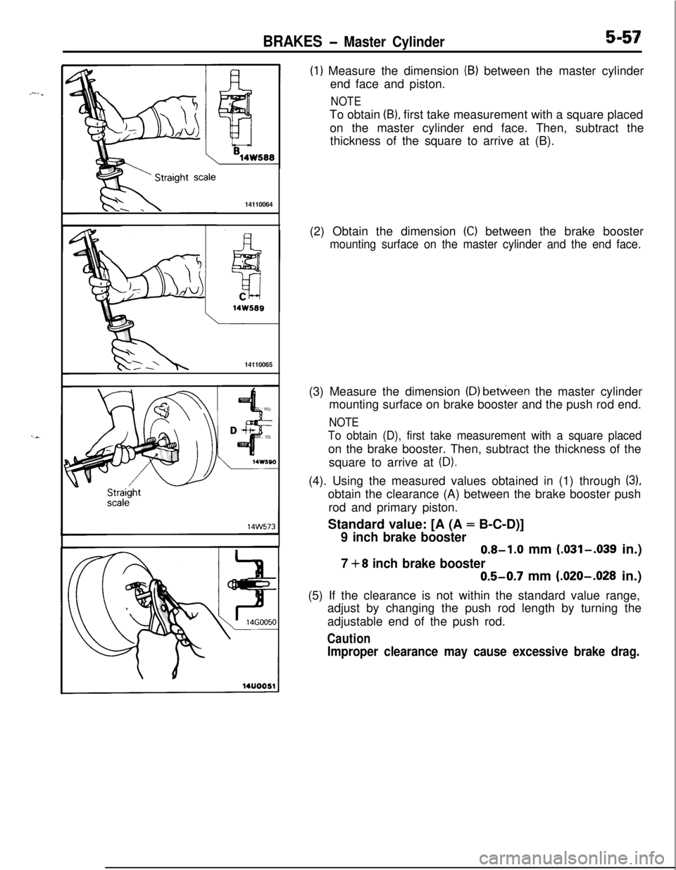
(1) Measure the dimension (B) between the master cylinder
end face and piston.
NOTETo obtain
(B), first take measurement with a square placed
on the master cylinder end face. Then, subtract the
thickness of the square to arrive at (B).
14110065(2) Obtain the dimension
(C) between the brake booster
mounting surface on the master cylinder and the end face.(3) Measure the dimension
(D) between the master cylinder
mounting surface on brake booster and the push rod end.
NOTE
To obtain (D), first take measurement with a square placedon the brake booster. Then, subtract the thickness of the
square to arrive at
(D).(4). Using the measured values obtained in (1) through
(3),obtain the clearance (A) between the brake booster push
rod and primary piston.
Standard value: [A (A = B-C-D)]
9 inch brake booster0.8-1.0 mm
(.031-.039 in.)
7 +8 inch brake booster0.5-0.7 mm
(.020-.028 in.)
(5) If the clearance is not within the standard value range,
adjust by changing the push rod length by turning the
adjustable end of the push rod.
Caution
Improper clearance may cause excessive brake drag.
Page 268 of 1216
7-20COOLING - Water Pump <1.8L Engine>
aWater pump*<
l-----r,//
O-ringWater
pipe
04ROO24Identification
mark04lJoo25Alternater
brace
404uoo22
J
SERVICE POINTS OF INSTALLATIONN07ME40a
26. INSTALLATION OF O-RINGsInsert the O-ring to the water inlet pipe, and coat the,buter
circumference of the O-ring with water.,
By coating with water, the insertion to the water pump will
become easier.
Caution
1.Care must be taken not to permit engine oil or other
greases to adhere to the O-ring.
2.When inserting the pipe, check to be sure,that there
is no sand, dirt, etc. on its inner surface.
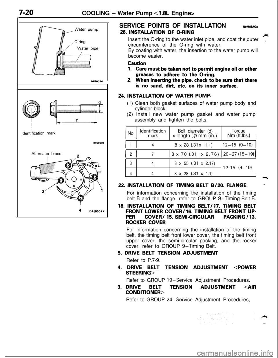
24. INSTALLATION OF WATER PUMP,
(1) Clean both gasket surfaces of water pump body and
cylinder block.
(2) Install new water pump gasket and water pump
assembly and tighten the bolts.
Bolt diameter (d)Torque
x length (e) mm (in.)Nm (ftlbs.)I
I I148 x 28 (.31 x 1.1)112-15 (9-10) 1
I I2
71 8 x 70 (.31 x 2.76) 120-27 (15-19)(
348x55(.31x2.17)12-15(9-10)
448x28(.31x1.1)I
22. INSTALLATION OF TIMING BELT B/20. FLANGE-For information concerning the installation of the timing
belt
B and the flange, refer to GROUP g-Timing Belt B.
18. INSTALLATION OF TIMING BELT/l7. TIMING BELT
FRONT LOWER COVER/lG. TIMING BELT FRONT UP-
PERCOVER/ 15. SEMI-CIRCULARPACKING / 13.
ROCKER COVERFor information concerning the installation of the timing
belt, the timing belt front lower cover, the timing belt front
upper cover, the semi-circular packing, and the rocker
cover, refer to GROUP
g-Timing Belt.
5. DRIVE BELT TENSION ADJUSTMENT
Refer to
P.7-9.
4. DRIVE BELT TENSION ADJUSTMENT
Refer to GROUP
19-Service Adjustment Procedures.
3. DRIVEBELTTENSIONADJUSTMENT
Refer to GROUP
24-Service Adjustment Procedures,
Page 272 of 1216
7-24COOLING - Water Pump <2.0L DOHC Engine>
Identification mark
4lternater brace
6COOOlO
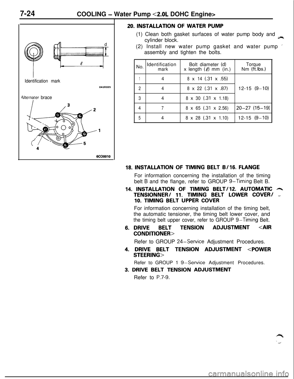
20. INSTALLATION OF WATER PUMP
(1) Clean both gasket surfaces of water pump body and
jir,cylinder block.
(2) Install new water pump gasket and water pump ’
assembly and tighten the bolts.
No, IdentificationBolt diameter (d)Torquemarkx length (I?) mm (in.)Nm (ft.lbs.1
148x14(.31x.55)
248x22(.31x.87)12-15(g-10)
348x30(.31x1.18)
4
78x65(.31x2.56)20-27(15-191
548x28(.31x1.10)12-15(g-10)
18. INSTALLATION OF TIMING BELT B/16. FLANGEFor information concerning the installation of the timing
belt
B and the flange, refer to GROUP g-Timing Belt B.
14. INSTALLATION OF TIMING BELT/lZ. AUTOMATIC 6TENSlONNER/
11. TIMING BELT LOWER COVER/ -
10. TIMING BELT UPPER COVERFor information concerning installation of the timing belt,
the automatic tensioner, the timing belt lower cover, and
the timing belt upper cover, refer to GROUP g-Timing Belt.
6. DRIVEBELT TENSIONADJUSTMENT
Refer to GROUP
24-Service Adjustment Procedures.
4. DRIVE BELT TENSION ADJUSTMENT
Refer to GROUP 1
g-Service Adjustment Procedures.
3. DRIVE BELT TENSION ADJUSTMENT
Refer to
P.7-9.
Page 293 of 1216
ENGINE - SpecificationsItems
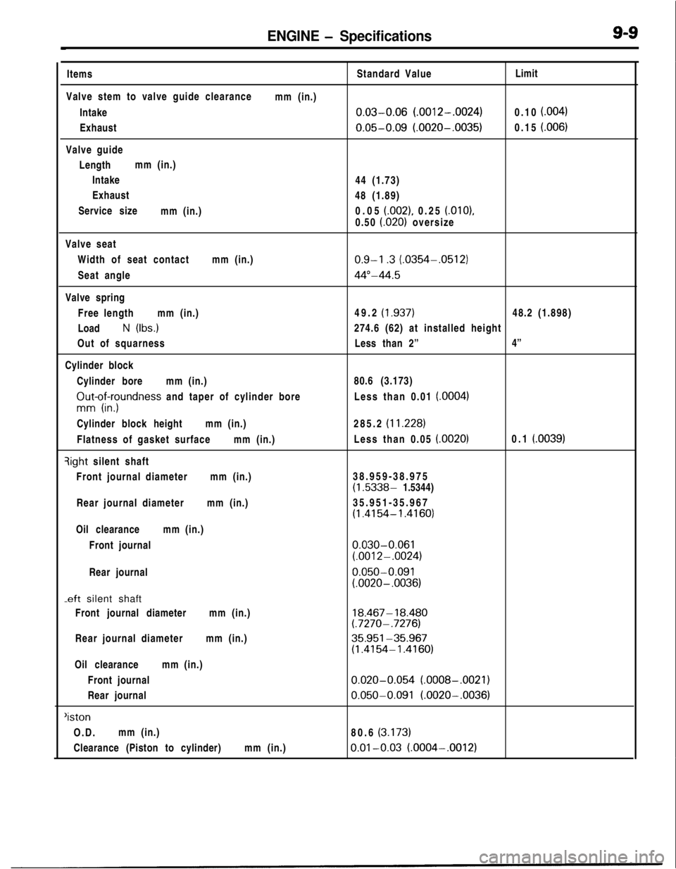
Valve stem to valve guide clearance
Intake
Exhaust
Valve guide
Lengthmm (in.)
Intake
Exhaust
Service size
mm (in.)mm (in.)Standard Value
0.03-0.06 (.0012-.0024)
0.05-0.09 (.0020-.0035)44 (1.73)
48 (1.89)
0.05
(.002), 0.25 (.OlO),
0.50
i.020) oversizeLimit
0.10
f.004)0.15
i.006)Valve seat
Width of seat contactmm (in.)
Seat angle
Valve spring
Free lengthmm (in.)
Load
N (Ibs.)
Out of squarness
Cylinder block
Cylinder boremm (in.)
ZIut-of;yundness and taper of cylinder bore
Cylinder block heightmm (in.)
Flatness of gasket surfacemm (in.)qight silent shaft
Front journal diametermm (in.)
Rear journal diametermm (in.)
Oil clearancemm (in.)
Front journal
Rear journal
-eft silent shaft
Front journal diametermm (in.)
Rear journal diametermm (in.)
Oil clearancemm (in.)
Front journal
Rear journal
‘istonO.D.mm (in.)
Clearance (Piston to cylinder)mm (in.)
0.9-l .3 (.0354-.0512)
44”-44.549.2
(1.937)48.2 (1.898)
274.6 (62) at installed height
Less than 2”4”
80.6 (3.173)
Less than 0.01
(.0004)285.2
(11.228)Less than 0.05
(.0020)0.1 (.0039)38.959-38.975
(1.5338- 1.5344)
35.951-35.967
(1.4154- 1.4160)
0.030-0.061(.0012-.0024)
0.050-0.091(.0020- .0036)
18.467- 18.480(.7270- .7276)
35.951-35.967(1.4154-1.4160)
0.020-0.054 (.0008-.0021)
0.050-0.091 (.0020-.0036)80.6
(3.173)
0.01-0.03 (.0004-.0012)
Page 294 of 1216
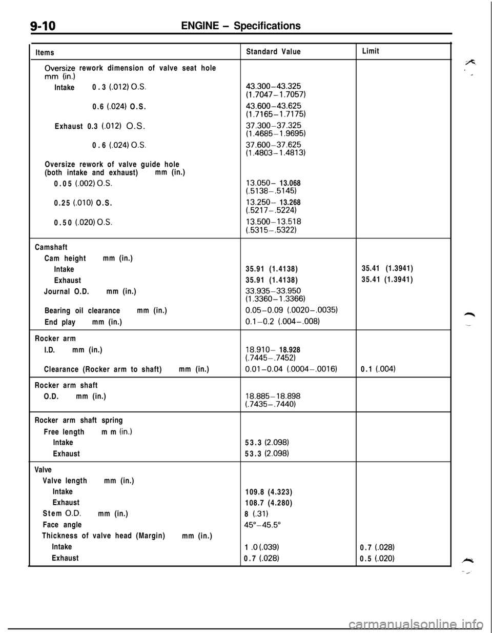
9-10ENGINE - SpecificationsItems
rIvrs,iz; rework dimension of valve seat hole
Intake0.3
(012) O.S.0.6
(024) O.S.
Exhaust 0.3
(.012) O.S.
0.6
(024) OS.Oversize rework of valve guide hole
(both intake and exhaust)mm (in.)
0.05
(.002) O.S.0.25
(.OlO) O.S.
0.50
(.020) O.S.Standard Value
43.300-43.325
(1.7047- 1.7057)
43.600-43.625
(1.7165-1.7175)
37.300-37.325(1.4685- 1.9695)
37.600-37.625(1.4803- 1.4813)
13.050- 13.068(.5138-.5145)
13.250- 13.268(.5217-.5224)
13.500-13.518
(.5315-.5322)Limit
Camshaft
Cam heightmm (in.)
Intake35.91 (1.4138)35.41 (1.3941)
Exhaust35.91 (1.4138)35.41 (1.3941)
Journal O.D.mm (in.)
33.935-33.950(1.3360- 1.3366)Bearing oil clearancemm (in.)
0.05-0.09 (.0020-.0035)End playmm (in.)
0.1-0.2 (.004-,008)Rocker arm
I.D.mm (in.)
18.910- 18.928
(.7445- .7452)Clearance (Rocker arm to shaft)mm (in.)
0.01-0.04 (.0004-.0016)0.1 (004)Rocker arm shaft
O.D.mm (in.)
18.885- 18.898(.7435-.7440)Rocker arm shaft spring
Free lengthmm (in.)
Intake
Exhaust
Valve
Valve lengthmm (in.)
Intake
Exhaust
Stem
O.D.mm (in.)
Face angle
Thickness of valve head (Margin)
Intake
Exhaust53.3
(2.098)53.3
(2.098)109.8 (4.323)
108.7 (4.280)
8
(.31)
45”-45.5”mm (in.)
1 .o
(.039)0.7 (028)0.7
(.028)0.5 (.020)
Page 296 of 1216
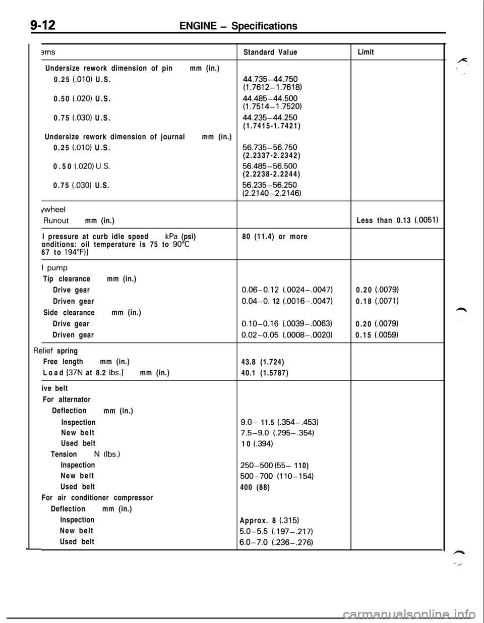
9-12ENGINE - Specifications3msStandard ValueLimit
Undersize rework dimension of pinmm (in.)
0.25
f.010) U.S.44.735-44.750
(1.7612-1.7618)0.50
(.020) U.S.44.485-44.500
(1.7514-1.7520)0.75
(030) U.S.44.235-44.250(1.7415-1.7421)
Undersize rework dimension of journalmm (in.)
0.25
(.OlO) U.S.56.735-56.750(2.2337-2.2342)
0.50
(020) U.S.56.485-56.500(2.2238-2.2244)
0.75
(.030) U.S.56.235-56.250
(2.2140-2.2146)
wheelRunoutmm (in.)Less than 0.13
(0051)I pressure at curb idle speedkPa (psi)80 (11.4) or more
onditions: oil temperature is 75 to
90°C67 to 194”F)l
1 w-wTip clearancemm (in.)
Drive gear
0.06-0.12 (.0024-.0047)0.20 i.0079)Driven gear
0.04-O. 12 (.0016-.0047)0.18 (.0071)Side clearancemm (in.)
Drive gear
0.10-0.16 (.0039-.0063)0.20 (.0079)Driven gear
0.02-0.05 (.0008-.0020)0.15 (.0059)
rlief spring
Free lengthmm (in.)
43.8 (1.724)
Load
[37N at 8.2 Ibs.]mm (in.)
40.1 (1.5787)
ive belt
For alternator
Deflection
mm (in.)
Inspection
9.0- 11.5 (.354-,453)New belt
7.5-9.0 (.295-.354)Used belt
10
i.394)TensionN (Ibs.)
Inspection
250-500 (55- 110)
New belt
500-700 (110-154)Used belt
400 (88)
For air conditioner compressor
Deflectionmm (in.)
Inspection
Approx. 8
(315)New belt
5.0-5.5 (.197-.217)Used belt
6.0-7.0 (.236-.276)