steering wheel MITSUBISHI ECLIPSE 1991 Owner's Guide
[x] Cancel search | Manufacturer: MITSUBISHI, Model Year: 1991, Model line: ECLIPSE, Model: MITSUBISHI ECLIPSE 1991Pages: 1216, PDF Size: 67.42 MB
Page 660 of 1216
19-12STEERING - Service Adjustment Procedures
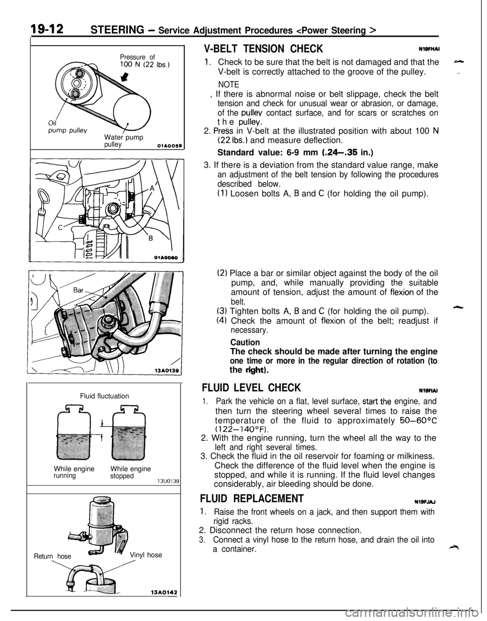
Pressure ofWater pump
pulleyOlA0059Fluid fluctuation
While engine
runningWhile enginestopped13uo139
Return hoseVinyl hose
x ,3Ao,42-
V-BELT TENSION CHECKNlSFliAl
1.Check to be sure that the belt is not damaged and that the
V-belt is correctly attached to the groove of the pulley.
NOTE, If there is abnormal noise or belt slippage, check the belt
tension and check for unusual wear or abrasion, or damage,
of the
pullev contact surface, and for scars or scratches onthe
pulley.2.
Press in V-belt at the illustrated position with about 100 N
(22 Ibs.) and measure deflection.
Standard value: 6-9 mm
1.26.35 in.)
3. If there is a deviation from the standard value range, make
an adjustment of the belt tension by following the procedures
described below.
(1) Loosen bolts A, B and C (for holding the oil pump).
(2) Place a bar or similar object against the body of the oil
pump, and, while manually providing the suitable
amount of tension, adjust the amount of
flexion of the
belt.
(3) Tighten bolts A, B and C (for holding the oil pump).
(4) Check the amount of flexion of the belt; readjust if
necessary.
CautionThe check should be made after turning the engine
one time or more in the regular direction of rotation (tothe
dght).
FLUID LEVEL CHECKNlSFIAI
1.Park the vehicle on a flat, level surface, startthe engine, andthen turn the steering wheel several times to raise the
temperature of the fluid to approximately
50-60°C
(122-140°F).2. With the engine running, turn the wheel all the way to the
left and right several times.3. Check the fluid in the oil reservoir for foaming or milkiness.
Check the difference of the fluid level when the engine is
stopped, and while it is running. If the fluid level changes
considerably, air bleeding should be done.
FLUID REPLACEMENTNlSFJAJ
1.Raise the front wheels on a jack, and then support them with
rigid racks.2. Disconnect the return hose connection.
3.Connect a vinyl hose to the return hose, and drain the oil into
a container.
Page 661 of 1216
STEERING - Service -Adjustment Procedures < Power Steering >IgJf~
4.Disconnect the high-tension cable, and then while operating
the starting motor intermittently, turn the steering wheel all;
the way to the left and right several times to drain all of the
fluid.
Caution, 35
Be careful not to position thq high-tension able ye&r the
carburetor or the delivery pipe.5. Connect the return hoses securely, and then
secur& it ,with
the clip.6. Fill the oil reservoir with the specified fluid up
td the Ibwerposition of the filter, and then bleed the air.
.’
Specified fluid:MOPAR ATF PLUS (Automatic Transmis-sion Fluid Type 7176)/Automatic trans-
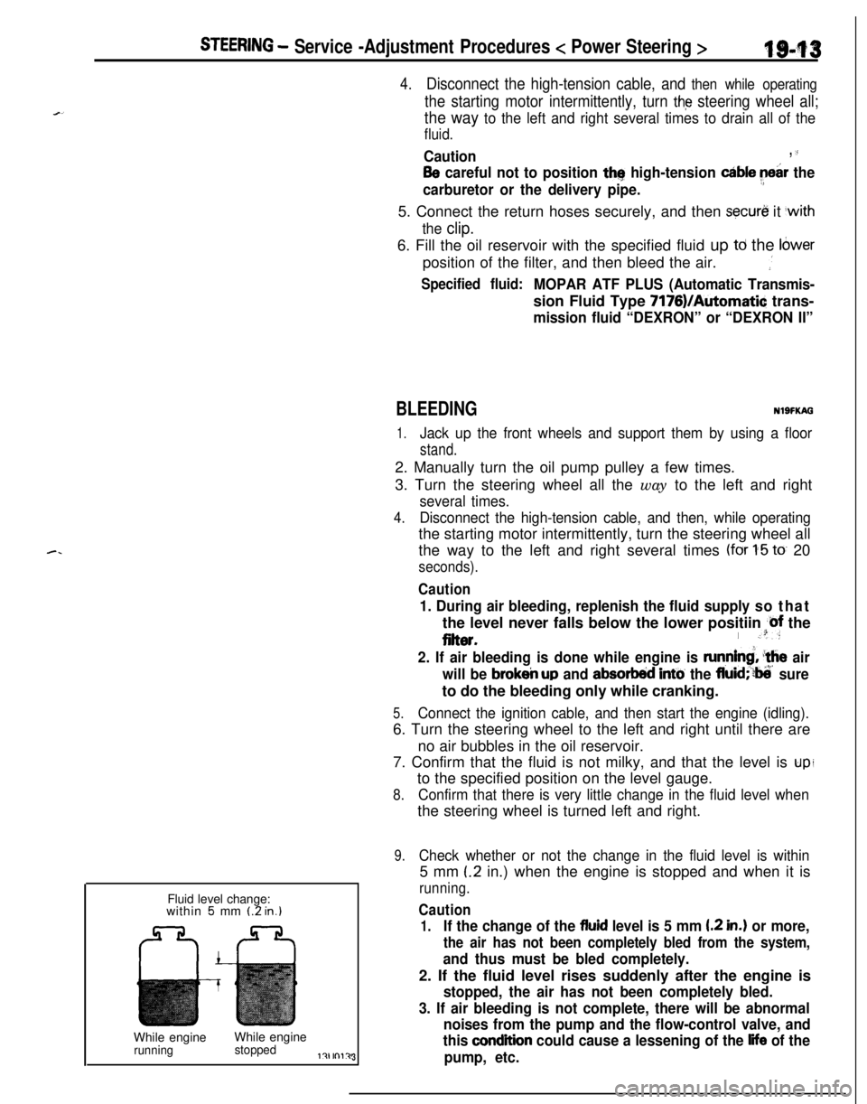
mission fluid “DEXRON” or “DEXRON II”Fluid level change:
within
5 mm (2 in.)While engineWhile engine
runningstoppedl?lrnl?J3
BLEEDINGNlSFKAG
1.Jack up the front wheels and support them by using a floor
stand.2. Manually turn the oil pump pulley a few times.
3. Turn the steering wheel all the way to the left and right
several times.
4.Disconnect the high-tension cable, and then, while operatingthe starting motor intermittently, turn the steering wheel all
the way to the left and right several times
(for 1-5 to 20
seconds).
Caution
1. During air bleeding, replenish the fluid supply so thatthe level never falls below the lower positiin
@f the
eiter.I .“:
2. If air bleeding is done while engine is runnind, ‘the air
will be
brokeir up and absorbed intti the fluid;‘?ti’ sureto do the bleeding only while cranking.
5.Connect the ignition cable, and then start the engine (idling).6. Turn the steering wheel to the left and right until there are
no air bubbles in the oil reservoir.
7. Confirm that the fluid is not milky, and that the level is
upito the specified position on the level gauge.
8.Confirm that there is very little change in the fluid level whenthe steering wheel is turned left and right.
9.Check whether or not the change in the fluid level is within5 mm
(.2 in.) when the engine is stopped and when it is
running.
Caution
1.If the change of the fluid level is 5 mm I.2 in.) or more,
the air has not been completely bled from the system,
and thus must be bled completely.2. If the fluid level rises suddenly after the engine is
stopped, the air has not been completely bled.
3. If air bleeding is not complete, there will be abnormal
noises from the pump and the flow-control valve, and
this
condition could cause a lessening of the life of the
pump, etc.
Page 662 of 1216
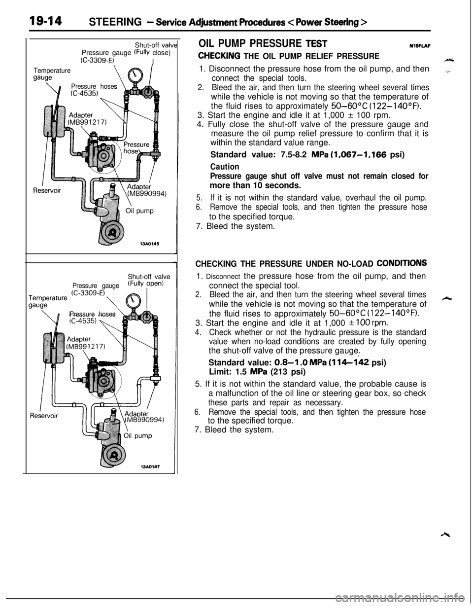
19-14STEERING - Service Adjustment Procedures < Power Steering >Shut-off valv
Pressure gauge
(FW close)
(C-3309-E)I
Temperature
gauge
\e’\
Pressure hoses
Re(Mti990994)
\Oil pump
713AO145Shut-off valve
Pressure gauge(FullY ?penl
Pressure hoses
OIL PUMP PRESSURE TESTNl9FlAF
CHECKING THE OIL PUMP RELIEF PRESSURE1. Disconnect the pressure hose from the oil pump, and then
connect the special tools.
2.Bleed the air, and then turn the steering wheel several timeswhile the vehicle is not moving so that the temperature of
the fluid rises to approximately
50-60°C (122-14OOF).3. Start the engine and idle it at 1,000
f 100 rpm.
4. Fully close the shut-off valve of the pressure gauge and
measure the oil pump relief pressure to confirm that it is
within the standard value range.
Standard value: 7.5-8.2
MPa (1,067-1,166 psi)
Caution
Pressure gauge shut off valve must not remain closed formore than 10 seconds.
5.If it is not within the standard value, overhaul the oil pump.
6.Remove the special tools, and then tighten the pressure hoseto the specified torque.
7. Bleed the system.
CHECKING THE PRESSURE UNDER NO-LOAD CONDITIONS1. Disconnect the pressure hose from the oil pump, and then
connect the special tool.
2.Bleed the air, and then turn the steering wheel several timeswhile the vehicle is not moving so that the temperature of
the fluid rises to approximately
50-60°C (122-14OOF).3. Start the engine and idle it at 1,000
-t 100 rpm.
4.
Check whether or not the hydraulic pressure is the standard
value when no-load conditions are created by fully openingthe shut-off valve of the pressure gauge.
Standard value:
0.8-I .O MPa (114-142 psi)
Limit: 1.5
MPa (213 psi)
5. If it is not within the standard value, the probable cause is
a malfunction of the oil line or steering gear box, so check
these parts and repair as necessary.
6.Remove the special tools, and then tighten the pressure hoseto the specified torque.
7. Bleed the system.
Page 663 of 1216
-
c. .
STEERING - Service Adiustment Procedures
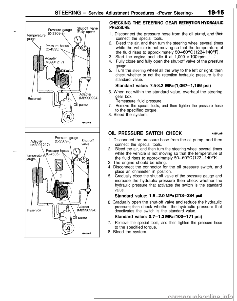
Shut-off valve
Pressure gauge
CHECKING THE STEERING GEAR PETENTION HYDRAULIC
PRESSURE1. Disconnect the pressure hose from the oil
pbmd, and iheh
connect the special tools.
2.Bleed the air, and then turn the steering wheel several timeswhile the vehicle is not moving so that the temperature of
the fluid rises to approximately
50~60OC (122~14pyF).
3. ‘Start the engine and idle it at 1,000 +
100 rem: .‘,’.
4.Fully close and fully open the shut-off valve of the pressure
gauge.
5.Turn the steering wheel all the way to the left or right; then
check whether or not the retention hydraulic pressure is the
standard value.
Standard value: 7.5-8.2 MPa (1,067-1,166 psi)6. When not within the standard value, overhaul the steering
gear box.
Remeasure fluid pressure.
7.Remove the special tools, and then tighten the pressure hoseto the specified torque.
8. Bleed the system.
OIL PRESSURE SWITCH CHECKNlSFUAB1. Disconnect the pressure hose from the oil pump, and then
connect the special tools.
2.Bleed the air, and then turn the steering wheel several timeswhile the vehicle is not moving so that the temperature of
the fluid rises to approximately
50-60°C (122-14OOF).3. The engine should be idling.
4. Disconnect the connector for the oil pressure switch, and
place an ohmmeter ,in position.
5.Gradually close the shut-off valve of the pressure gauge andincrease the hydraulic pressure then check whether the
hydraulic pressure that activates the switch is the standard
value.
Standard value: 1.5-2.0 MPa (213-284 psi)
6. Gradually open the shut-off valve and reduce the hydraulic
pressure; then check whether the hydraulic pressure that
deactivates the switch is the standard value.
Standard value: 0.7-1.2 MPa (100-171 psi)
7.Remove the special tools, and then tighten the pressure hoseto the specified torque.
8. Bleed the system.
Page 664 of 1216
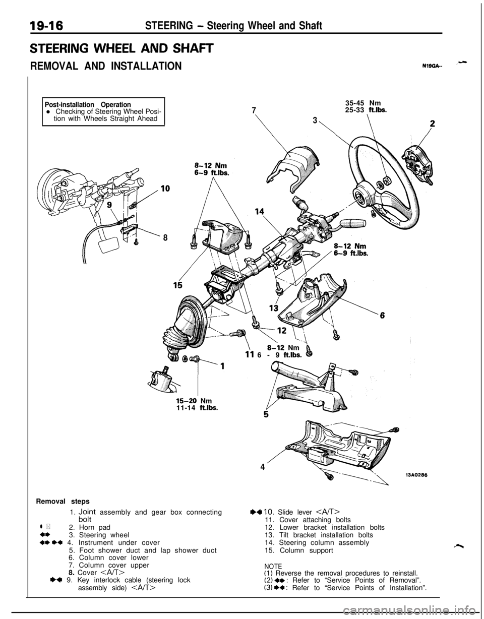
19-16STEERING - Steering Wheel and Shaft
STEERING WHEEL AND SHAFT
REMOVAL AND INSTALLATIONNlL)GA- ‘-
Post-installation Operationl Checking of Steering Wheel Posi-
tion with Wheels Straight Ahead
835-45 Nm
725-33 ft.lbs.
\
3
\\
15-20 Nm
11-14 ft.lbs.Removal steps
1.
“,c$t assembly and gear box connecting
l *2. Horn pad
4*3. Steering wheel
+* ++ 4. Instrument under cover
5. Foot shower duct and lap shower duct
6. Column cover lower
7. Column cover upper
8. Cover
assembly side)
\8-i2 Nm’11 6-9 ft.lbs.0
413AO296
+4 10. Slide lever 11. Cover attaching bolts
12. Lower bracket installation bolts
13. Tilt bracket installation bolts
14. Steering column assembly
15. Column support
NOTE(I) Reverse the removal procedures to reinstall.(2) a* : Refer to “Service Points of Removal”.(3) +a : Refer to “Service Points of Installation”.
Page 665 of 1216
STEERING - Steering Wheel and Shaft
1610778
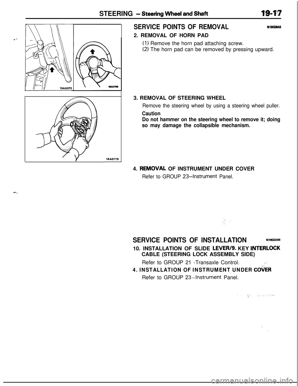
SERVICE POINTS OF REMOVALNlBGBAS2. REMOVAL OF HORN PAD
(1) Remove the horn pad attaching screw.
(2) The horn pad can be removed by pressing upward.
3. REMOVAL OF STEERING WHEEL
Remove the steering wheel by using a steering wheel puller.
Caution
Do not hammer on the steering wheel to remove it; doing
so may damage the collapsible mechanism.4.
.REMOVAL OF INSTRUMENT UNDER COVER
Refer to GROUP 234nstrument Panel.
SERVICE POINTS OF INSTALLATIONNlgGDAN10. INSTALLATION OF SLIDE
LEVER/S. KEY !NTERLOCKCABLE (STEERING LOCK ASSEMBLY SIDE)
Refer to GROUP 21 -Transaxle Control.
.::
4. INSTALLATION OF INSTRUMENT UNDER COiiERRefer to GROUP
23-Instrument Panel.
,I
Page 666 of 1216
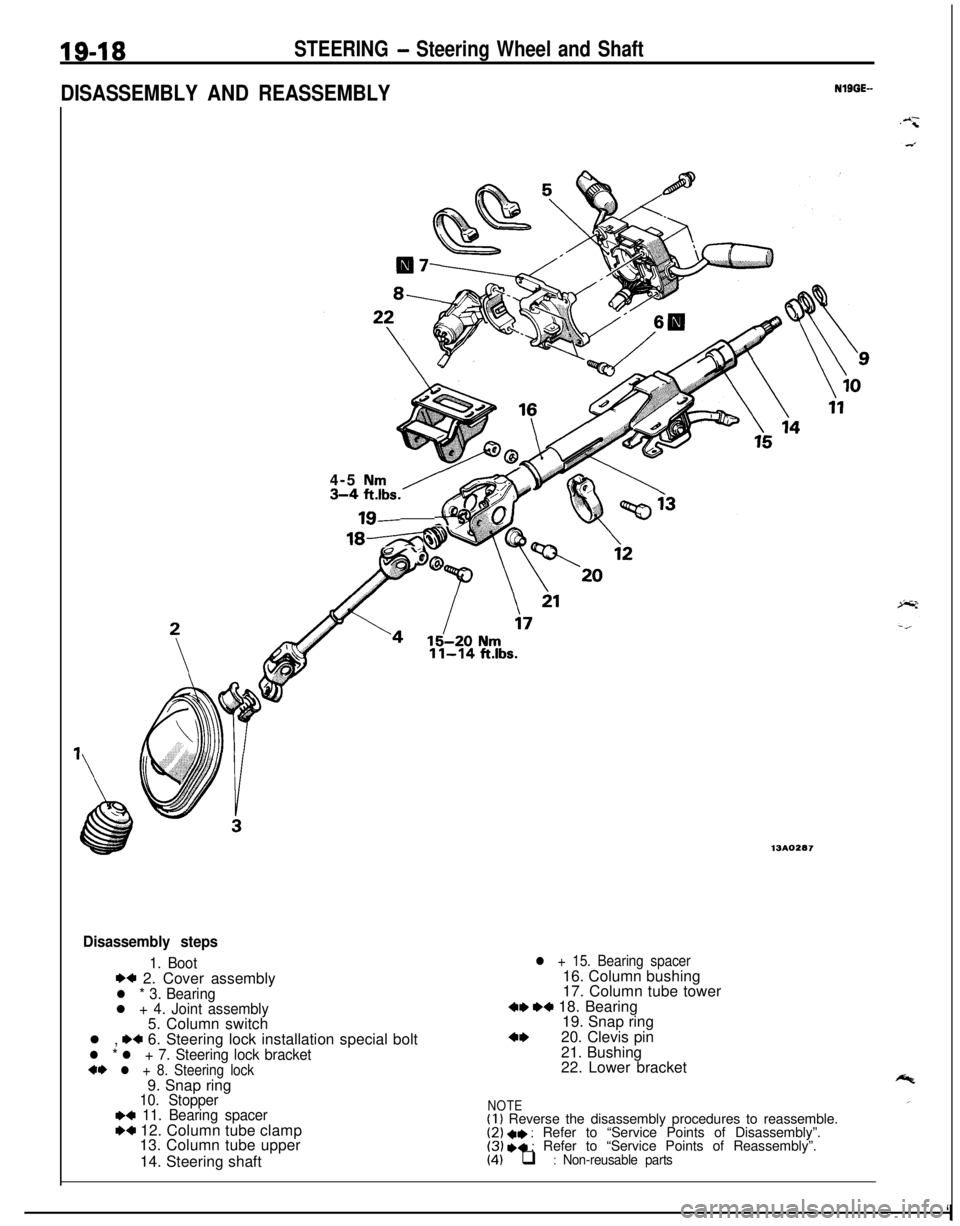
19-18STEERING - Steering Wheel and Shaft
DISASSEMBLY AND REASSEMBLYNlBGE-
4-5
Nm3-4;lbs. -6
18-z.
11-14 ft.lbs.
13AO287
Disassembly steps
1. Boot*+ 2. Cover assemblyl * 3. Bearingl + 4. Joint assembly5. Column switch
l ,
.+ 6. Steering lock installation special boltl * l + 7. Steering lock bracket+I) l + 8. Steering lock9. Snap ring
10. Stopper~~ 11. Bearing spacerW 12. Column tube clamp
13. Column tube upper
14. Steering shaft
l + 15. Bearing spacer16. Column bushing
17. Column tube tower
4, ,+ 18. Bearing
19. Snap ring
4,20. Clevis pin
21. Bushing
22. Lower bracket
NOTE(I 1 Reverse the disassembly procedures to reassemble.(2) +I) : Refer to “Service Points of Disassembly”.(3) I)+ : Refer to “Service Points of Reassembly”.(4) q : Non-reusable parts
‘I
Page 667 of 1216
STEERING - Steering Wheel and Shaft
Socket13AO106
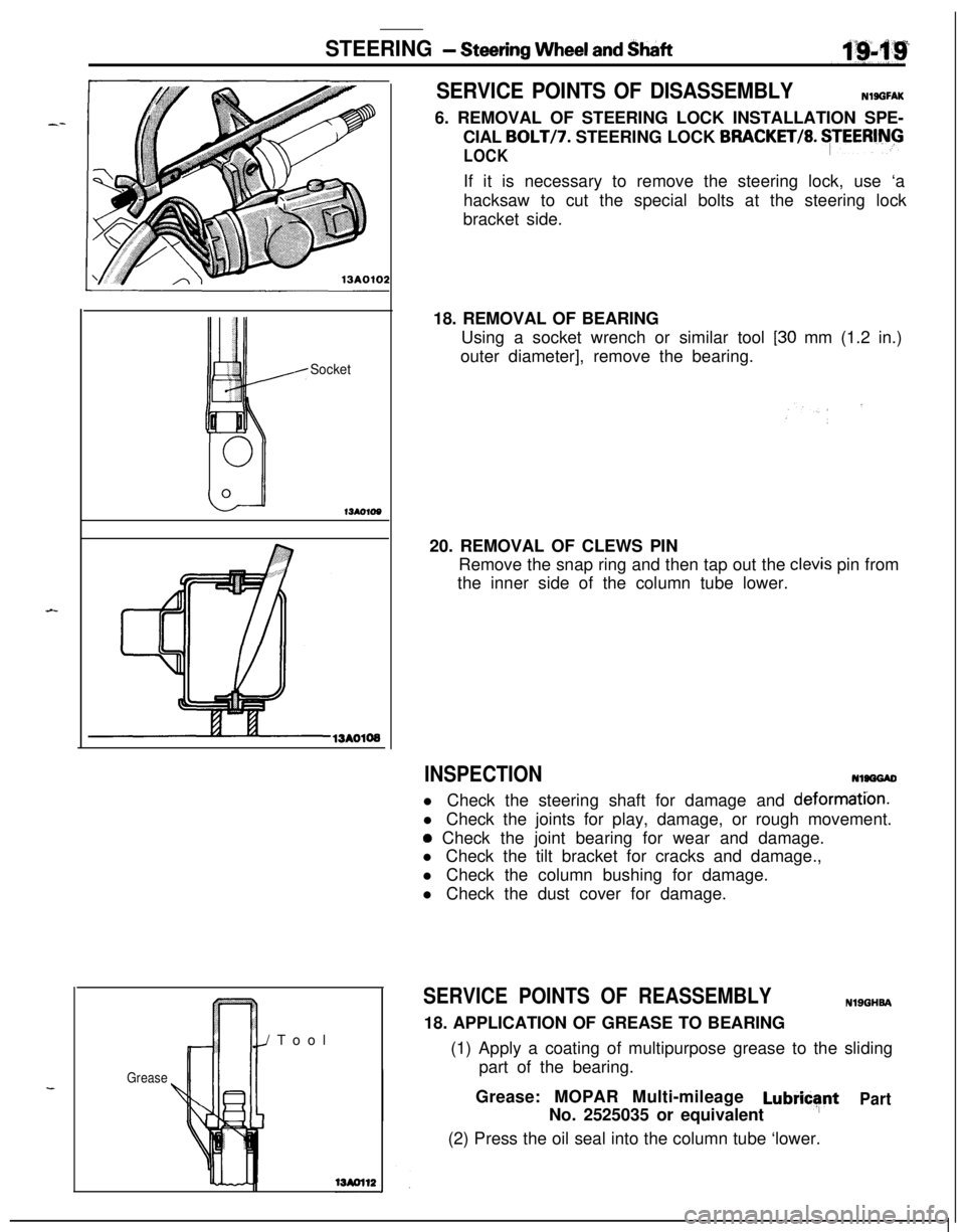
SERVICE POINTS OF DISASSEMBLYNlSGFAK6. REMOVAL OF STEERING LOCK INSTALLATION SPE-
CIAL
BOLTI7. STEERING LOCK BRACKET/8. $EERlNG
LOCKIf it is necessary to remove the steering lock, use ‘a
hacksaw to cut the special bolts at the steering lock
bracket side.
18. REMOVAL OF BEARING
Using a socket wrench or similar tool
[30 mm (1.2 in.)
outer diameter], remove the bearing.
20. REMOVAL OF CLEWS PIN
Remove the snap ring and then tap out the
clevis pin from
the inner side of the column tube lower.
INSPECTIONNlSGGADl Check the steering shaft for damage and
deformati’on.l Check the joints for play, damage, or rough movement.
a Check the joint bearing for wear and damage.
l Check the tilt bracket for cracks and damage.,
l Check the column bushing for damage.
l Check the dust cover for damage.
Grease/Tool
SERVICE POINTS OF REASSEMBLYNlSGHSA18. APPLICATION OF GREASE TO BEARING
(1) Apply a coating of multipurpose grease to the sliding
part of the bearing.
Grease: MOPAR Multi-mileage
LubricsfntPartNo. 2525035 or equivalent
(2) Press the oil seal into the column tube ‘lower.
Page 668 of 1216
19-20STEERING - Steering Wheel and Shaft
13AOWColumn tube Column
I18.5W.5 mm
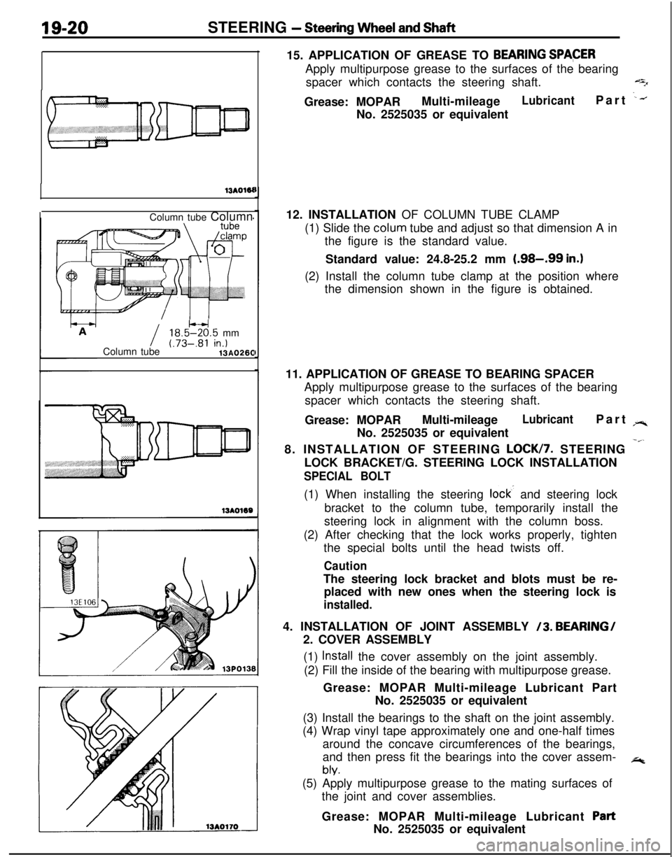
Column tube(.73-.81 in.)13AO26015. APPLICATION OF GREASE TO
BEARING SPACERApply multipurpose grease to the surfaces of the bearing
spacer which contacts the steering shaft.
qGrease: MOPARMulti-mileage
LubricantPart .--.No. 2525035 or equivalent
12. INSTALLATION OF COLUMN TUBE CLAMP
(1) Slide the colum tube and adjust so that dimension A in
the figure is the standard value.
Standard value: 24.8-25.2 mm
(.98-.99 in.)(2) Install the column tube clamp at the position where
the dimension shown in the figure is obtained.
11. APPLICATION OF GREASE TO BEARING SPACER
Apply multipurpose grease to the surfaces of the bearing
spacer which contacts the steering shaft.
Grease: MOPARMulti-mileage
LubricantPart rr.No. 2525035 or equivalent
8. INSTALLATION OF STEERING
LOCK/7. STEERING -”LOCK BRACKET/G. STEERING LOCK INSTALLATION
SPECIAL BOLT(1) When installing the steering
lock- and steering lock
bracket to the column tube, temporarily install the
steering lock in alignment with the column boss.
(2) After checking that the lock works properly, tighten
the special bolts until the head twists off.
CautionThe steering lock bracket and blots must be re-
placed with new ones when the steering lock is
installed.4. INSTALLATION OF JOINT ASSEMBLY
/3. BEARING/
2. COVER ASSEMBLY
(1)
Install the cover assembly on the joint assembly.
(2) Fill the inside of the bearing with multipurpose grease.
Grease: MOPAR Multi-mileage Lubricant Part
No. 2525035 or equivalent
(3) Install the bearings to the shaft on the joint assembly.
(4) Wrap vinyl tape approximately one and one-half times
around the concave circumferences of the bearings,
and then press fit the bearings into the cover assem-
*
bly.(5) Apply multipurpose grease to the mating surfaces of
the joint and cover assemblies.
Grease: MOPAR Multi-mileage Lubricant
PartNo. 2525035 or equivalent
Page 676 of 1216
19-28STEERING - Power Steering Gear Box
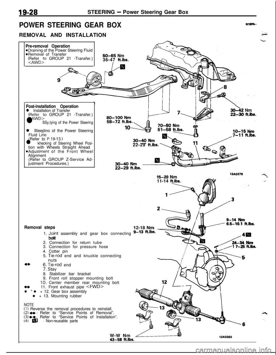
POWER STEERING GEAR BOXREMOVAL AND INSTALLATION
-
NlSPA--
Pre-removal Operation@Draining of the Power Steering Fluid@Removal of Transfer:1&&r:, GROUP 21 -Transfer.)50-65 Nm36-47 ft.lbs.
I/a
Post-installation Operationl Installation of Transfer(:zD:” GROUP 21 -Transfer.)
l SSy,lying of the Power Steeringl Bleedino of the Power Steering
Fluid
Liie(Refer to P.19-13.1l khecking of Steering Wheel Posi-tion with Wheels Straight Ahead*Adjustment of the Front Wheel
Alignment
(Refer to GROUP Z-Service Ad-
justment Procedures.)
Removal steps1.
“,;;rt assembly and gear box connecting
bolt
2. Connection for return tube
3. Connection for pressure hose
4. Cotter pin
5.
Aft-cd end and knuckle connecting
4I)f3: H,“a:od end
8. Stabilizer bar bracket
9. Front roll stopper mounting bolt10. Center member rear mounting bolt
4411. Front exhaust pipe
l + 13. Mounting rubber
(I) Reverse the removal procedures to reinstall.(2) +e : Refer to “Service Points of Removal”.(3) .* : Refer to “Service Points of Installation”.(4) q : Non-reusable parts(4) lli
3oh2 Nm22-30 ftlba.^a-aa I.au-IUU NrnI
IO-15 Nm22-29
ft.lbs.
15-20 Nm15-20 Nm
11-14 ft.lbs.
13A027612-18 Nm
A-34 IUm
K-
1 j-+ft.lbs.
:II I-.5
/ .2!
i!!1
NOTEW-W Nm43-58
ft.lbs.13A0353