steering wheel MITSUBISHI ECLIPSE 1991 Owner's Manual
[x] Cancel search | Manufacturer: MITSUBISHI, Model Year: 1991, Model line: ECLIPSE, Model: MITSUBISHI ECLIPSE 1991Pages: 1216, PDF Size: 67.42 MB
Page 495 of 1216
FUEL SYSTEM - Service Adjustment Procedures <1.8L Engine>l-4-41
SERVICE ADJUSTMENT PROCEDURES
CURB IDLE SPEED INSPECTION
CautionNlIFiiAE
The improper setting (throttle valve opening) will increase
exhaust gas temperature at deceleration, reducing catalystlife greatly and deteriorating exhaust gas cleaning per-
formance. It also has effect on fuel consumption and
engine braking.
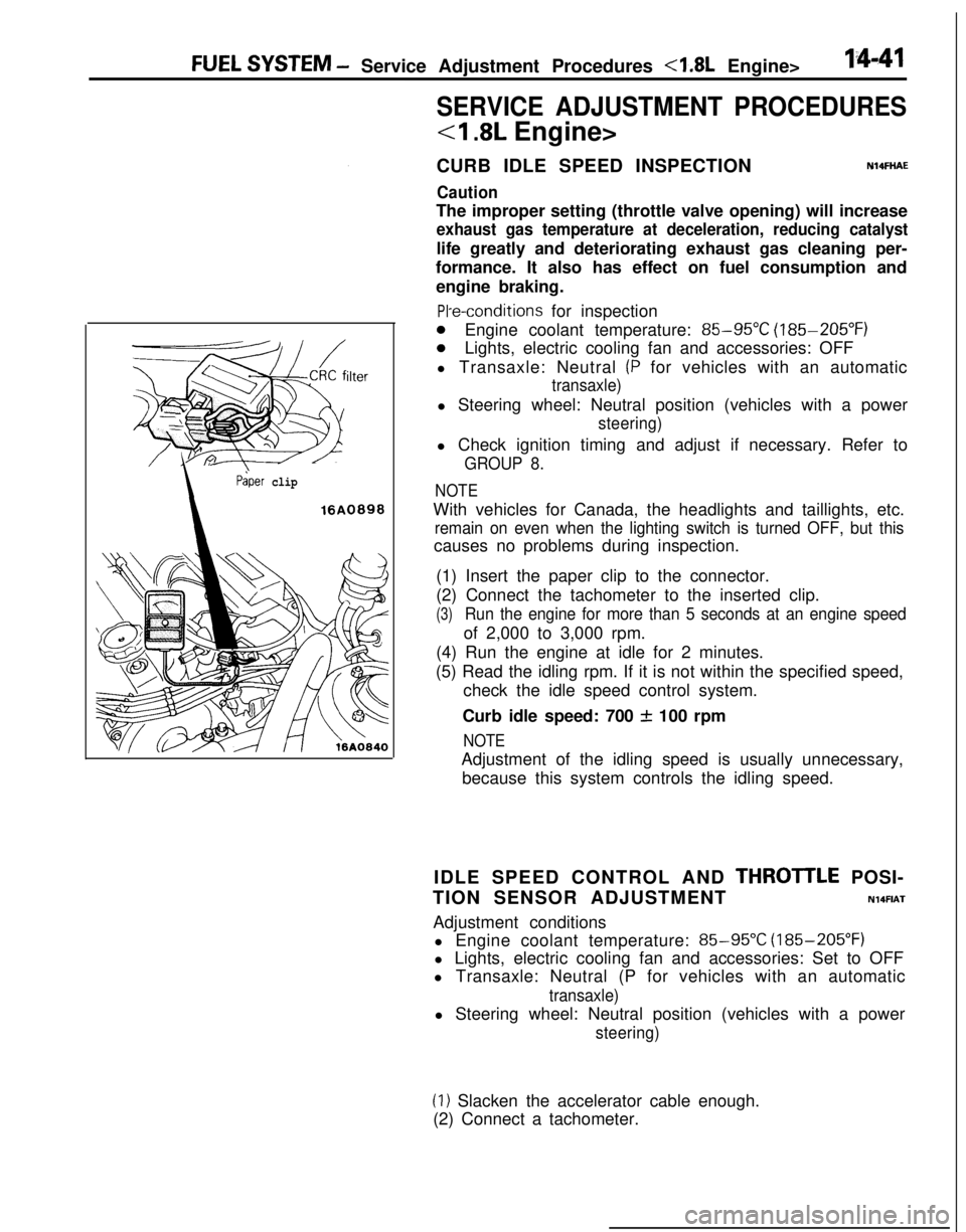
ilter
Paper clip
16A0898
PI-e-conditions for inspection
0Engine coolant temperature: 85-95°C (185-205°F)
0Lights, electric cooling fan and accessories: OFF
l Transaxle: Neutral
(P for vehicles with an automatic
transaxle)l Steering wheel: Neutral position (vehicles with a power
steering)l Check ignition timing and adjust if necessary. Refer to
GROUP 8.
NOTEWith vehicles for Canada, the headlights and taillights, etc.
remain on even when the lighting switch is turned OFF, but thiscauses no problems during inspection.
(1) Insert the paper clip to the connector.
(2) Connect the tachometer to the inserted clip.
(3)Run the engine for more than 5 seconds at an engine speedof 2,000 to 3,000 rpm.
(4) Run the engine at idle for 2 minutes.
(5) Read the idling rpm. If it is not within the specified speed,
check the idle speed control system.
Curb idle speed: 700
f 100 rpm
NOTEAdjustment of the idling speed is usually unnecessary,
because this system controls the idling speed.
IDLE SPEED CONTROL AND
THROTlLE POSI-
TION SENSOR ADJUSTMENT
N14FIATAdjustment conditions
l Engine coolant temperature:
85-95X (185-205°F)
l Lights, electric cooling fan and accessories: Set to OFF
l Transaxle: Neutral (P for vehicles with an automatic
transaxle)l Steering wheel: Neutral position (vehicles with a power
steering)
(1) Slacken the accelerator cable enough.
(2) Connect a tachometer.
Page 502 of 1216
14-48FUEL SYSTEM - Service Adjustment Procedures <2.0L Engine>
SERVICE ADJUSTMENT PROCEDURES
<2.0L DOHC Engine>
CURB IDLE SPEED INSPECTION
Caution
N14FHADThe improper setting (throttle valve opening) will increase
exhaust gas temperature at deceleration, reducing
catalys-tic converter life greatly and deteriorating exhaust gas
cleaning performance. It also has effect on fuel ‘consump-
tion and engine braking.
Pre-conditions for inspection
l Engine coolant temperature:
85-95°C (185-205°F)
l Lights, electric cooling fan and accessories: OFF
lTransaxle: Neutral (P for vehicles with automatic transaxle)l Steering wheel: Neutral position (vehicles with a power-
steering)l Check ignition timing and adjust if necessary. Refer to
GROUP 8.
NOTEWith vehicles for Canada, the headlights and taillights, etc.
remain on even when the lighting switch is turned OFF, but thiscauses no problems during inspection.
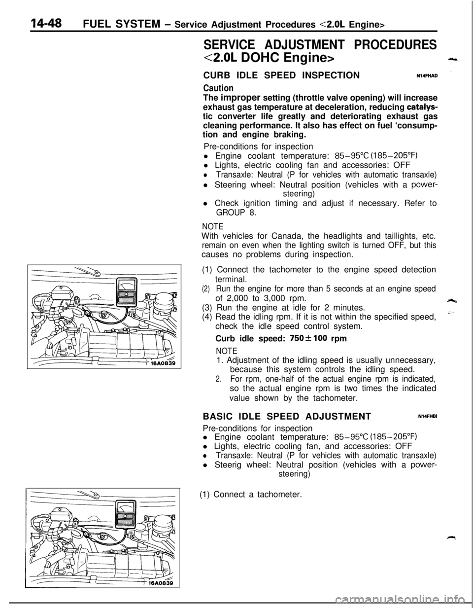
(1) Connect the tachometer to the engine speed detection
terminal.
(2)Run the engine for more than 5 seconds at an engine speedof 2,000 to 3,000 rpm.
(3) Run the engine at idle for 2 minutes.
(4) Read the idling rpm. If it is not within the specified speed,
check the idle speed control system.
Curb idle speed:
750f 100 rpm
NOTE1. Adjustment of the idling speed is usually unnecessary,
because this system controls the idling speed.
2.For rpm, one-half of the actual engine rpm is indicated,so the actual engine rpm is two times the indicated
value shown by the tachometer.
BASIC IDLE SPEED ADJUSTMENT
N14FHBIPre-conditions for inspection
l Engine coolant temperature:
85-95°C (185-205°F)
l Lights, electric cooling fan, and accessories: OFF
lTransaxle: Neutral (P for vehicles with automatic transaxle)l Steerig wheel: Neutral position (vehicles with a
power-
steering)(1) Connect a tachometer.
Page 649 of 1216
STEERING
CONTENTSNISAA-
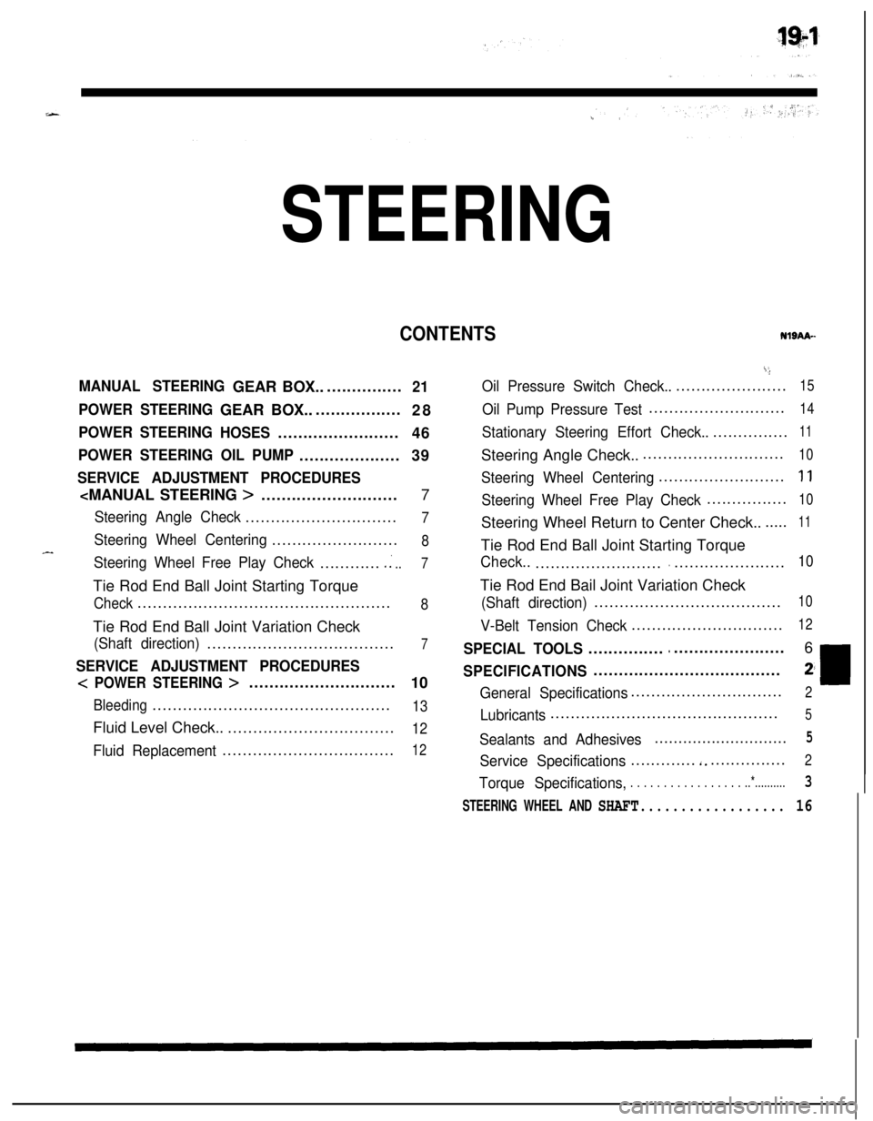
MANUAL STEERINGGEAR BOX.................21
POWER STEERINGGEAR BOX...................
28
POWER STEERING
HOSES........................
46
POWER STEERING OIL PUMP....................39
SERVICE ADJUSTMENT PROCEDURES
Steering Angle Check..............................7
Steering Wheel Centering.........................8
Steering Wheel Free Play Check.............:..7Tie Rod End Ball Joint Starting Torque
Check..................................................8Tie Rod End Ball Joint Variation Check
(Shaft direction).....................................7
SERVICE ADJUSTMENT PROCEDURES
< POWER STEERING >.............................
10
Bleeding...............................................13Fluid Level Check...................................
12
Fluid Replacement..................................12
i;,
Oil Pressure Switch Check........................15
Oil Pump Pressure Test...........................14
Stationary Steering Effort Check.................11Steering Angle Check..............................
10
Steering Wheel Centering.........................1 1
Steering Wheel Free Play Check................10Steering Wheel Return to Center Check.......
11Tie Rod End Ball Joint Starting Torque
Check..................................................10Tie Rod End Bail Joint Variation Check
(Shaft direction).....................................10
V-Belt Tension Check..............................12
SPECIAL TOOLS......................................6
SPECIFICATIONS.....................................2;
General Specifications..............................2
Lubricants.............................................5
Sealants and Adhesives............................5
Service Specifications.............‘................2
Torque Specifications,. . . . . . . . . . . . . . . . . ..*..........3
STEERING WHEEL AND SHAFT.................. 16
Page 650 of 1216
19-2STEERING - Specifications
SPECIFICATIONS
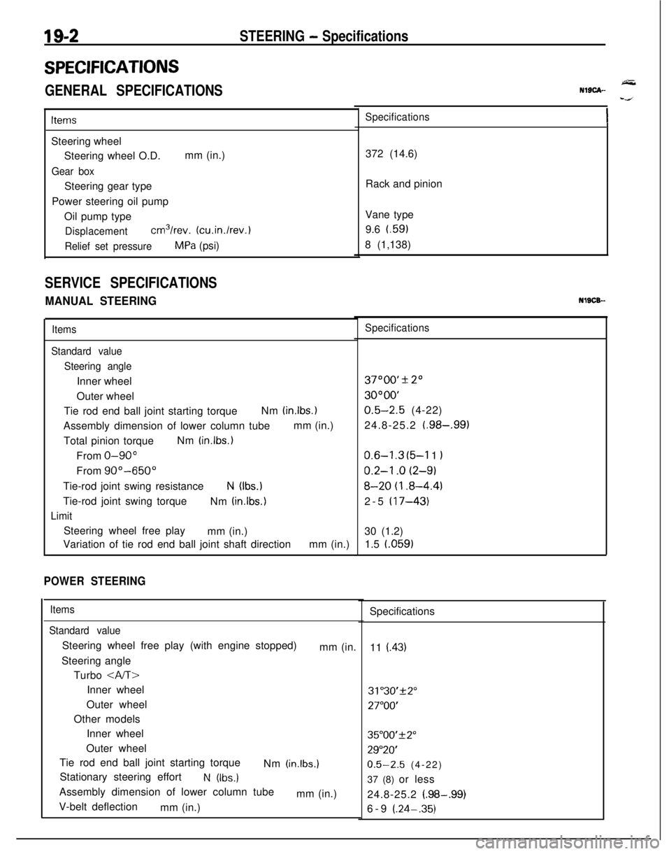
GENERAL SPECIFICATIONS
ItemsSteering wheel
Steering wheel O.D.mm (in.)
Gear boxSteering gear type
Power steering oil pump
Oil pump type
Displacementcm3/rev. (cu.in./rev.)
Relief set pressureMPa (psi)
SERVICE SPECIFICATIONS
MANUAL STEERING
Items
Standard value
Steering angleInner wheel
Outer wheel
Tie rod end ball joint starting torqueNm
(in.lbs.)Assembly dimension of lower column tubemm (in.)
Total pinion torqueNm
(in.lbs.)From
O-90”From
90”-650”Tie-rod joint swing resistance
N (Ibs.)Tie-rod joint swing torque
Nm
(in.lbs.)
LimitSteering wheel free play
mm (in.)
Variation of tie rod end ball joint shaft directionmm (in.)
POWER STEERING
Items
Standard valueSteering wheel free play (with engine stopped)
mm (in.
Steering angle
Turbo
Inner wheel
Outer wheel
Other models
Inner wheel
Outer wheel
Tie rod end ball joint starting torque
Nm
(in.lbs.)Stationary steering effort
N (Ibs.)Assembly dimension of lower column tube
mm (in.)
V-belt deflection
mm (in.)
NlSCA--
Specifications372 (14.6)
Rack and pinion
Vane type
9.6 t.59)
8 (1,138)NlSCB-
Specifications37000’
* 20
3OOOO’
0.5-2.5 (4-22)
24.8-25.2
(.98-,991
0.6-l .3 (5-l 1 I
0.2-l .o (2-9)
8-20 (I .8-4.4)2-5
(17-43)30 (1.2)
1.5 l.059)
Specifications
11
(.43)
31"30'+2"
27"OO'
35"00'f2"
29"20'
0.5-2.5 (4-22)
37 (8) or less
24.8-25.2
(.98-.99)6-9 (.24-.35)
Page 651 of 1216
-
STEERING - Specificdions
i’.g=s
“,.
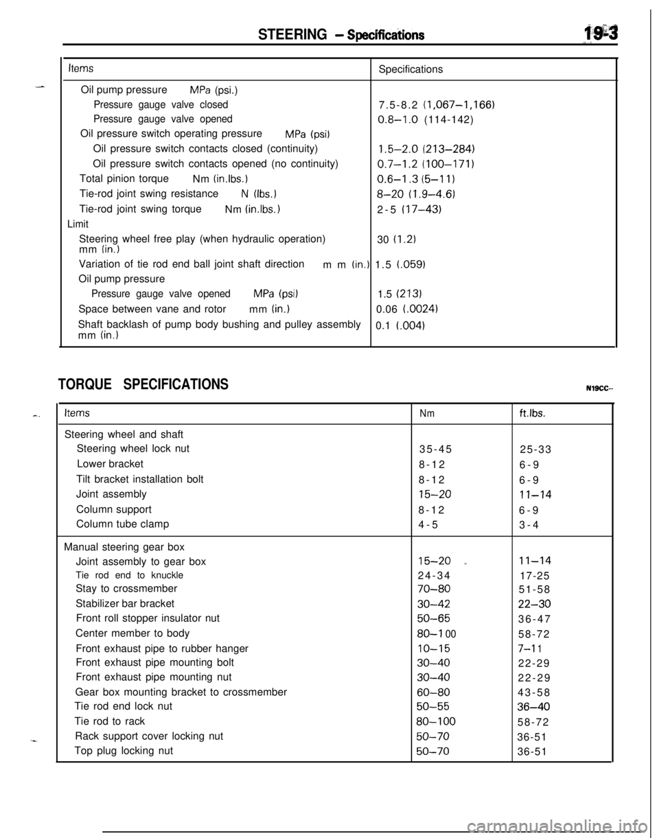
itemsSpecifications
Oil pump pressure
MPa (psi.)
Pressure gauge valve closed7.5-8.2 (1,067-1,166)
Pressure gauge valve opened0.8-I .O (114-142)
Oil pressure switch operating pressure
MPa (psi1Oil pressure switch contacts closed (continuity)
1.5-2.0 (213-284)Oil pressure switch contacts opened (no continuity)
0.7-1.2 (100-171)Total pinion torque
Nm
(in.lbs.)0.6-I .3 (5-l 1)Tie-rod joint swing resistance
N (Ibs.18-20 (1.9-4.6)Tie-rod joint swing torque
Nm
(in.lbs. 12-5 (17-43)
LimitSteering wheel free play (when hydraulic operation)
30
(1.2)mm (in.)Variation of tie rod end ball joint shaft direction
mm
(in.) 1.5 (.059)
Oil pump pressure
Pressure gauge valve openedMPa (psi)1.5 (213)Space between vane and rotor
mm
(in.)0.06 i.0024)Shaft backlash of pump body bushing and pulley assembly
0.1
i.004)mm (in.)
TORQUE SPECIFICATIONSNlSCC--
c.ItemsSteering wheel and shaft
Steering wheel lock nut
Lower bracket
Tilt bracket installation bolt
Joint assembly
Column support
Column tube clamp
Manual steering gear box
Joint assembly to gear box
Tie rod end to knuckle
Stay to crossmember
Stabilizer bar bracket
Front roll stopper insulator nut
Center member to body
Front exhaust pipe to rubber hanger
Front exhaust pipe mounting bolt
Front exhaust pipe mounting nut
Gear box mounting bracket to crossmember
Tie rod end lock nut
Tie rod to rack
Rack support cover locking nut
Top plug locking nutNmftlbs.35-45
25-33
8-12
6-9
8-12
6-9
15-2011-148-12
6-9
4-5
3-4
15-20 a11-1424-34
17-25
70-8051-58
30-4222-30
50-6536-47
80-l 0058-72
IO-157-l 1
30-4022-29
30-4022-29
60-8043-58
50-5536-40
80-10058-72
50-7036-51
50-7036-51
Page 655 of 1216
STEERING - Special Tools/Service Adjustment Procedures
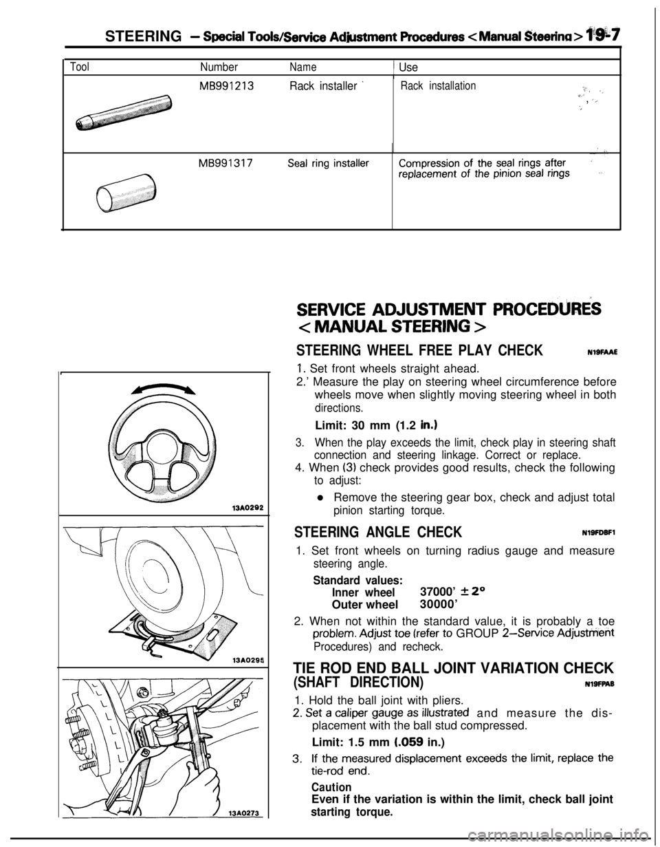
ToolNumberName1 UseI
MB991213Rack installer ’Rack installation:,.I/ ._i’, ‘,‘#
MB991317Seal ring installerCompression of the seal rings afterreplacement of the pinion seal rings13A0282
,
SERVICE ADJUSTMENT PROCEDURiS
< MANUAL STEERING >
STEERING WHEEL FREE PLAY CHECKNOSFAAE
1. Set front wheels straight ahead.
2.’ Measure the play on steering wheel circumference before
wheels move when slightly moving steering wheel in both
directions.Limit: 30 mm (1.2
in.1
3.When the play exceeds the limit, check play in steering shaft
connection and steering linkage. Correct or replace.4. When
(3) check provides good results, check the following
to adjust:l Remove the steering gear box, check and adjust total
pinion starting torque.
STEERING ANGLE CHECKNlSFDBFl1. Set front wheels on turning radius gauge and measure
steering angle.
Standard values:
Inner wheel37000’
2 20
Outer wheel30000’
2. When not within the standard value, it is probably a toe
problem. Adjust toe (refer to GROUP 2-Service Adjusttierit
Procedures) and recheck.
TIE ROD END BALL JOINT VARIATION CHECK
(SHAFT DIRECTION)NlSFPAB1. Hold the ball joint with pliers.
2. Set a caliper gauge as illustrated and measure the dis-
placement with the ball stud compressed.
Limit: 1.5 mm
LO59 in.)
3.If the measured displacement exceeds the limit, replace the
tie-rod end.
CautionEven if the variation is within the limit, check ball joint
starting torque.
Page 656 of 1216
19-8STEERING - Service Adjustment Procedures < Manual Steering>
136005!Tape or mark
on steering
column cover
Tape or mark
on steering
wheel hub16A0901
Dotted lines
show wheel
Tape or mark
on steering
wheel rim
nce off-center
16AOOOl
IO036 splines
;EEE;D END BALL JOINT STARTING TORQUE
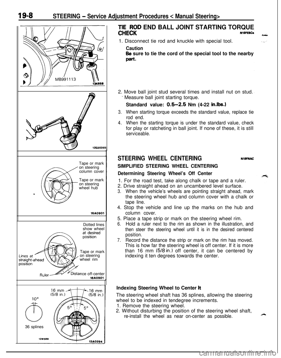
Nl9FEBCa1. Disconnect tie rod and knuckle with special tool.
Caution
Be sure to tie the cord of the special tool to the nearby
part-2. Move ball joint stud several times and install nut on stud.
’ Measure ball joint starting torque.
Standard value:
0.5-2.5 Nm (4-22 in.lbs.1
3.When starting torque exceeds the standard value, replace tie
rod end.
4.When the starting torque is under the standard value, checkfor play or ratcheting in ball joint. If none of these, it is still
serviceable.
STEERING WHEEL CENTERINGNlSFNAC
SIMPLIFIED STEERING WHEEL CENTERING
Determining Steering Wheel’s Off Center1. For the road test, take along chalk or tape and a ruler.
2. Drive straight ahead on an uncambered level surface.
3.When the vehicle’s wheels are pointing straight ahead, markthe steering wheel hub and column cover with a chalk or
tape line.4. Stop the vehicle and line up the marks on the hub and
column cover.5. Place a tape strip or mark on the steering wheel rim.
6.Hold a ruler next to the rim as shown in the illustration, and
then steer the steering wheel until it is in the desired centered
position.
7.Record the distance the strip or mark on the rim has moved.This is how far the steering wheel is off center. If it is more
than 16 mm
(518 in.) off center, it can be centered by
indexing it ten degrees towards the center.
,Indexing Steering Wheel to Center
ltThe steering wheel shaft has 36 splines, allowing the steering
wheel to be indexed in tendegree increments.
1. Remove the steering wheel.
2. Without disturbing the position of the steering wheel shaft,
re-install the wheel as near on-center as possible.
Page 657 of 1216
STEERING - Service Adjustment Procedures < Manual Steering>_ i ‘I 9;sSteering wheel off center left
13K71013A0289
Off center to leftOff center to left
Off center to rightOff center to right
Turn both tie rods in the same direction.
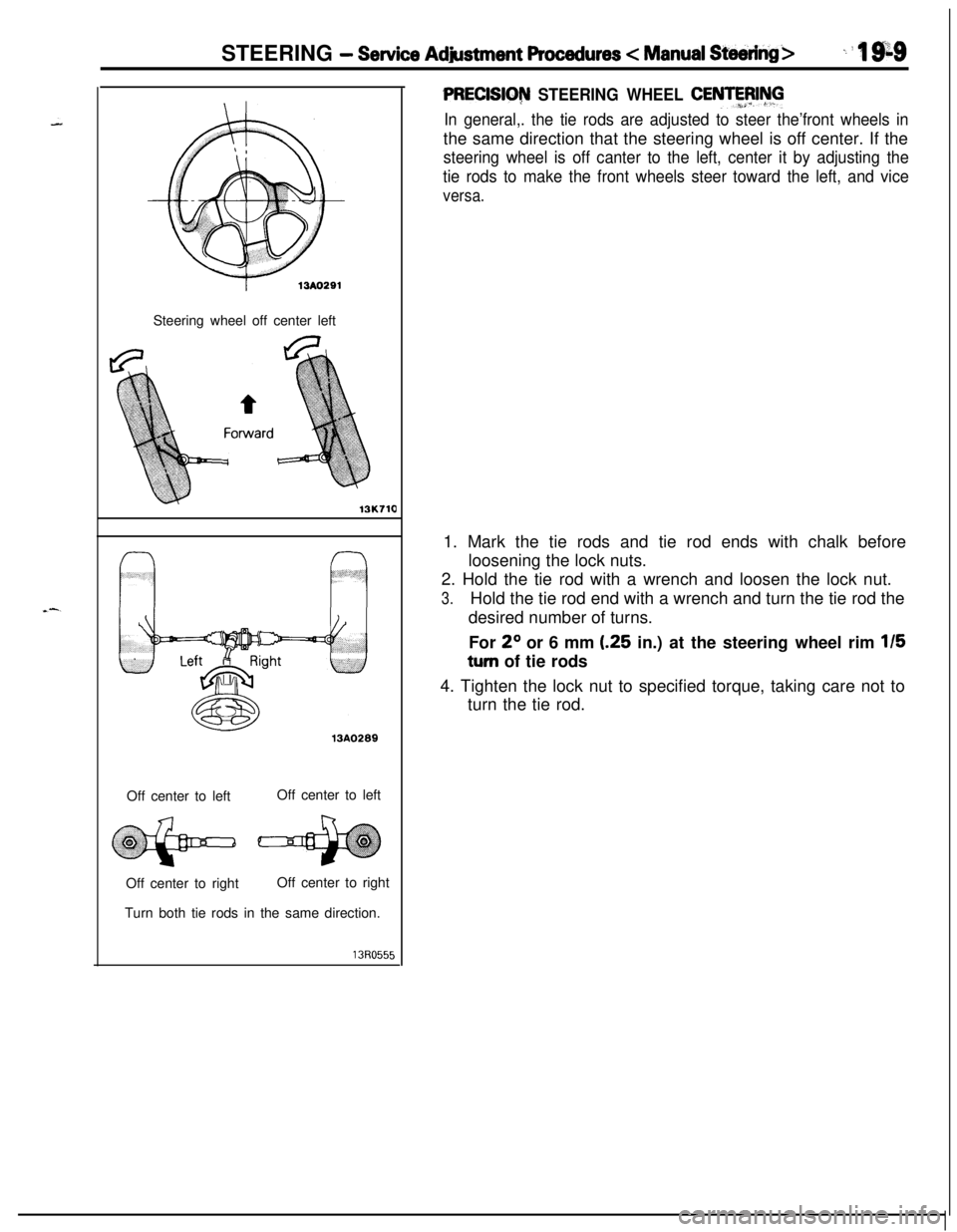
PRECISIG~ STEERING WHEEL CENTFFJIhll
In general,. the tie rods are adjusted to steer the’front wheels inthe same direction that the steering wheel is off center. If the
steering wheel is off canter to the left, center it by adjusting the
tie rods to make the front wheels steer toward the left, and vice
versa.1. Mark the tie rods and tie rod ends with chalk before
loosening the lock nuts.
2. Hold the tie rod with a wrench and loosen the lock nut.
3.Hold the tie rod end with a wrench and turn the tie rod the
desired number of turns.
For
2O or 6 mm (.25 in.) at the steering wheel rim 115
turn of tie rods
4. Tighten the lock nut to specified torque, taking care not to
turn the tie rod.
Page 658 of 1216
19-10STEERING - Service Adjustment Procedures c Power Steering>
r13A029213A0293
r
1
i
SERVICE ADJUSTMENT PROCEDURES
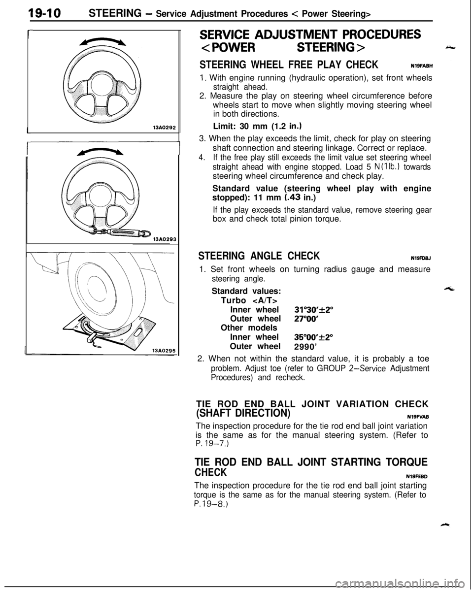
STEERING WHEEL FREE PLAY CHECKNlSFABH
1. With engine running (hydraulic operation), set front wheels
straight ahead.2. Measure the play on steering wheel circumference before
wheels start to move when slightly moving steering wheel
in both directions.
Limit: 30 mm (1.2
in.13. When the play exceeds the limit, check for play on steering
shaft connection and steering linkage. Correct or replace.
4.If the free play still exceeds the limit value set steering wheel
straight ahead with engine stopped. Load 5
N (1 lb.1 towardssteering wheel circumference and check play.
Standard value (steering wheel play with engine
stopped): 11 mm
I.43 in.)
If the play exceeds the standard value, remove steering gearbox and check total pinion torque.
STEERING ANGLE CHECKN19FDBJ1. Set front wheels on turning radius gauge and measure
steering angle.Standard values:
Turbo
Inner wheel
31”30’+2”Outer wheel
27”OOOther models
Inner wheel
35”00’_+2”Outer wheel
2990’
2. When not within the standard value, it is probably a toe
problem. Adjust toe (refer to GROUP 2-Service Adjustment
Procedures) and recheck.TIE ROD END BALL JOINT VARIATION CHECK
(SHAFT DIRECTION)N19FVA8The inspection procedure for the tie rod end ball joint variation
is the same as for the manual steering system. (Refer to
P. 19-7.)
TIE ROD END BALL JOINT STARTING TORQUE
CHECKNlSFEBDThe inspection procedure for the tie rod end ball joint starting
torque is the same as for the manual steering system. (Refer to
P.19-8.)
Page 659 of 1216
STEERING - Service Adjustment Procedures < Power Steering >194113AO29313AO290
STEERING WHEEL CENTERINGNlSFIYAFCenter the steering wheel in the same way as the manual
steering. (Refer to P.19-8.1
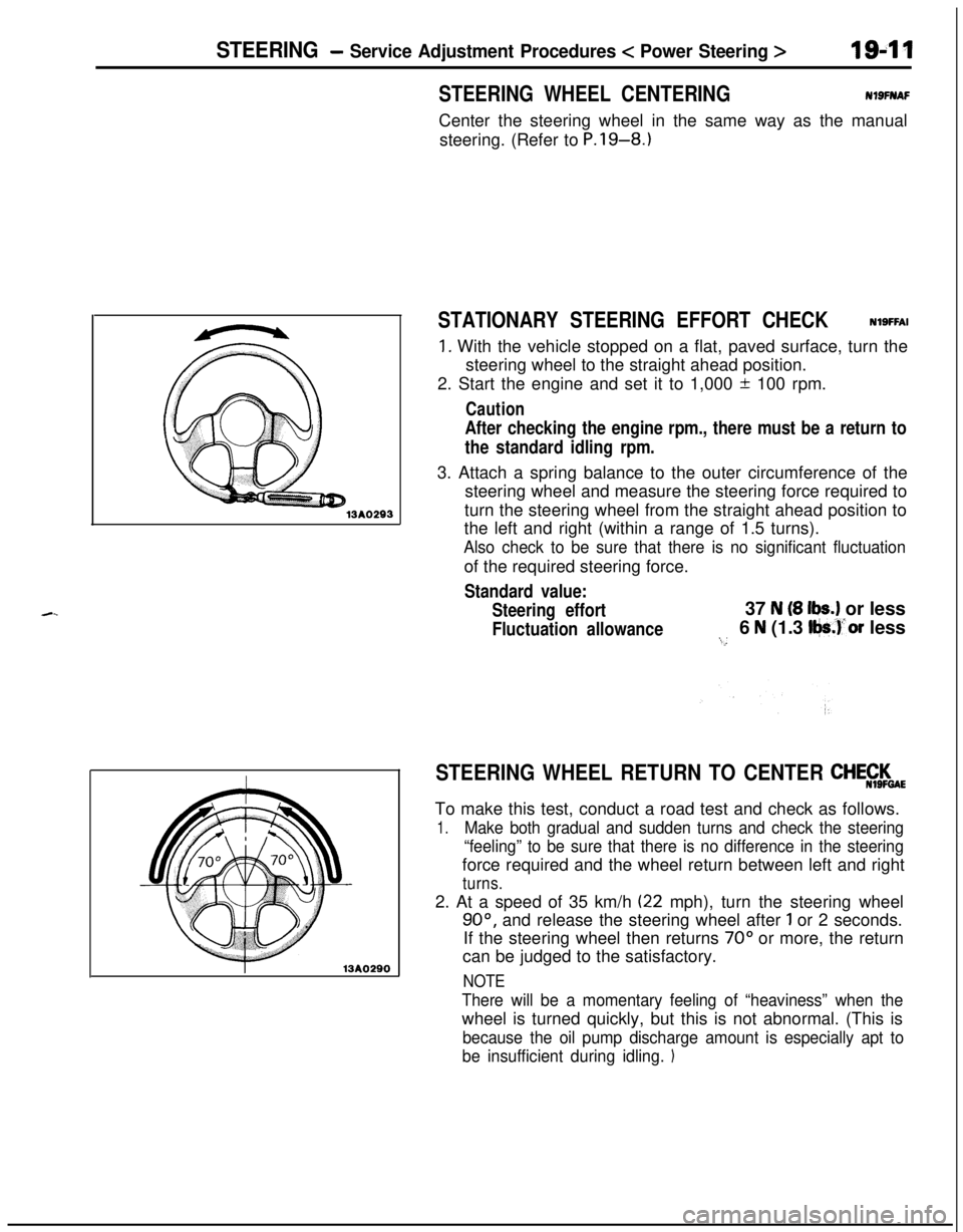
STATIONARY STEERING EFFORT CHECKNlSFFAI
1. With the vehicle stopped on a flat, paved surface, turn the
steering wheel to the straight ahead position.
2. Start the engine and set it to 1,000 + 100 rpm.
Caution
After checking the engine rpm., there must be a return to
the standard idling rpm.3. Attach a spring balance to the outer circumference of the
steering wheel and measure the steering force required to
turn the steering wheel from the straight ahead position to
the left and right (within a range of 1.5 turns).
Also check to be sure that there is no significant fluctuationof the required steering force.
Standard value:
Steering effort37
N (8 lbs.) or less
Fluctuation allowance6 N (1.3 Iljs.)‘or less:...
STEERING WHEEL RETURN TO CENTER CHE$$$aETo make this test, conduct a road test and check as follows.
1.Make both gradual and sudden turns and check the steering
“feeling” to be sure that there is no difference in the steeringforce required and the wheel return between left and right
turns.2. At a speed of 35 km/h
(22 mph), turn the steering wheel
90°, and release the steering wheel after 1 or 2 seconds.
If the steering wheel then returns
70” or more, the return
can be judged to the satisfactory.
NOTE
There will be a momentary feeling of “heaviness” when thewheel is turned quickly, but this is not abnormal. (This is
because the oil pump discharge amount is especially apt to
be insufficient during idling.
1