lock MITSUBISHI ECLIPSE 1991 Service Manual
[x] Cancel search | Manufacturer: MITSUBISHI, Model Year: 1991, Model line: ECLIPSE, Model: MITSUBISHI ECLIPSE 1991Pages: 1216, PDF Size: 67.42 MB
Page 2 of 1216
2INTRODUCTION AND MASTER TROUBLESHOOTING - How to Use This Manual
HOW TO USE THIS MANUALNOaM
CONTENTSThe preceding page contains GROUP INDEX which
lists the group title and group number.
PAGE NUMBERS
All page numbers consist of two sets of digits
separated by a dash. The digits preceding the dash
identify the
number of the group. The digits follow-
ing the dash represent the consecutive page num-
ber within the group. The page numbers can be
found on the top left or right of each page.
TEXT
Unless otherwise specified, each service procedurecovers all models. Procedures covering specific
models are identified by the model codes, or similar
designation (engine type, transaxle type, etc.). A
description of these designations is covered in this
unit under “VEHICLE IDENTIFICATION”.
TROUBLESHOOTING
Troubleshootings are classified into master trouble-
shooting and group troubleshooting and located as
follows:
The master troubleshooting is prepared when the
trouble symptom relates to two or more groups and
given in MASTER TROUBLESHOOTING.
The group troubleshooting guide is prepared for
causes of problems related to that individual group
only; a troubleshooting guide is prepared for each
appropriate group.LIMIT
-9Shows the standard for judging the quality of a part
-
or assembly on inspection and,means the maximumor minimum value within which the part or assembly
must be kept functionally or in strength.
It is a value
established outside the range of standard value.
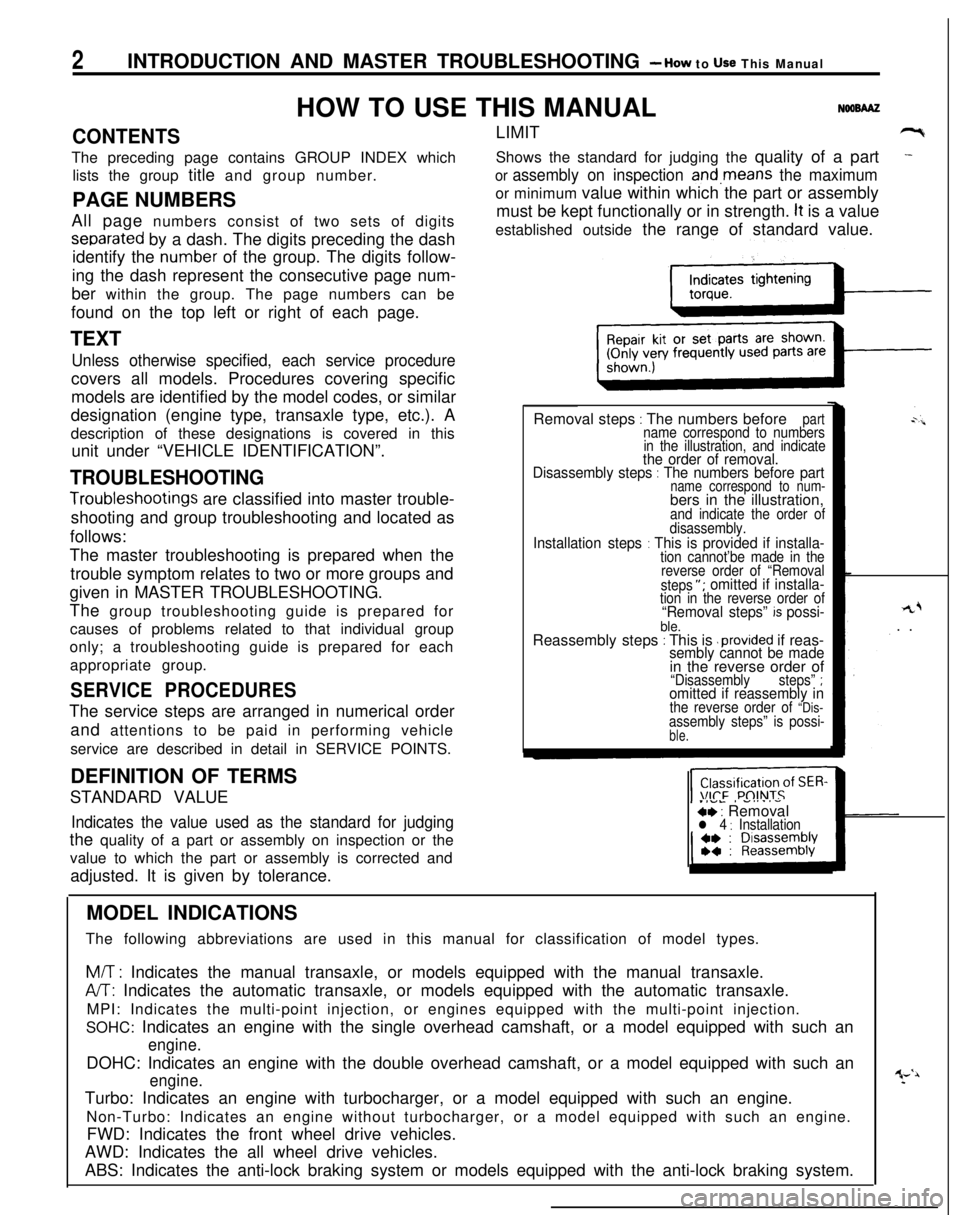
Removal steps
: The numbers beforepartname correspond to numbers
in the illustration, and indicate
the order of removal.
Disassembly steps : The numbers before partname correspond to num-bers in the illustration,
and indicate the order of
disassembly.
Installation steps : This is provided if installa-tion cannot’be made in the
reverse order of “Removal
steps
“; omitted if installa-tion in the reverse order of“Removal steps” k possi-ble.Reassembly steps : This is .provided if reas-sembly cannot be made
rL+. .
in the reverse order of
“Disassemblysteps” ;omitted if reassembly inthe reverse order of “Dis-assembly steps” is possi-ble.
SERVICE PROCEDURESThe service steps are arranged in numerical order
and attentions to be paid in performing vehicle
service are described in detail in SERVICE POINTS.
.IVL, -....-ce : Removall 4 : InstallationDEFINITION OF TERMS
STANDARD VALUEIndicates the value used as the standard for judgingthe quality of a part or assembly on inspection or the
value to which the part or assembly is corrected and
adjusted. It is given by tolerance.
MODEL INDICATIONS
The following abbreviations are used in this manual for classification of model types.
M/T : Indicates the manual transaxle, or models equipped with the manual transaxle.
A/T: Indicates the automatic transaxle, or models equipped with the automatic transaxle.
MPI: Indicates the multi-point injection, or engines equipped with the multi-point injection.
SOHC: Indicates an engine with the single overhead camshaft, or a model equipped with such an
engine.DOHC: Indicates an engine with the double overhead camshaft, or a model equipped with such an
engine.Turbo: Indicates an engine with turbocharger, or a model equipped with such an engine.
Non-Turbo: Indicates an engine without turbocharger, or a model equipped with such an engine.
FWD: Indicates the front wheel drive vehicles.
AWD: Indicates the all wheel drive vehicles.
ABS: Indicates the anti-lock braking system or models equipped with the anti-lock braking system.
Page 9 of 1216
INTRODUCTlON AND MASTER TROUBLESHOOTING - Vehicle Identification9
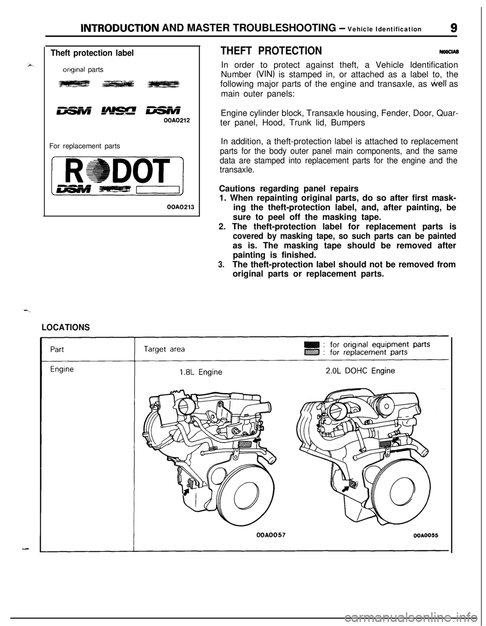
Theft protection label
onginal parts
w ,IeIW
B ,w w
OOA0212For replacement parts
OOA0213
LOCATIONS
THEFT PROTECTIONNowlABIn order to protect against theft, a Vehicle Identification
Number
WIN) is stamped in, or attached as a label to, the
following major parts of the engine and transaxle, as
tiell as
main outer panels:
Engine cylinder block, Transaxle housing, Fender, Door, Quar-
ter panel, Hood, Trunk lid, Bumpers
In addition, a theft-protection label is attached to replacement
parts for the body outer panel main components, and the same
data are stamped into replacement parts for the engine and the
transaxle.Cautions regarding panel repairs
1. When repainting original parts, do so after first mask-
ing the theft-protection label, and, after painting, be
sure to peel off the masking tape.
2. The theft-protection label for replacement parts is
covered by masking tape, so such parts can be paintedas is. The masking tape should be removed after
painting is finished.
3.The theft-protection label should not be removed from
original parts or replacement parts.
OOA0057OOA0055
Page 13 of 1216
INTRODUCTION AND MASTER TROUBLESHOOTING - Precautions befdre Service‘1 S
OOV663OOY192
FOOO 1.
FOOO18
0
OOD511
J7
PRECAUTIONS BEFORE SERVICE wxww
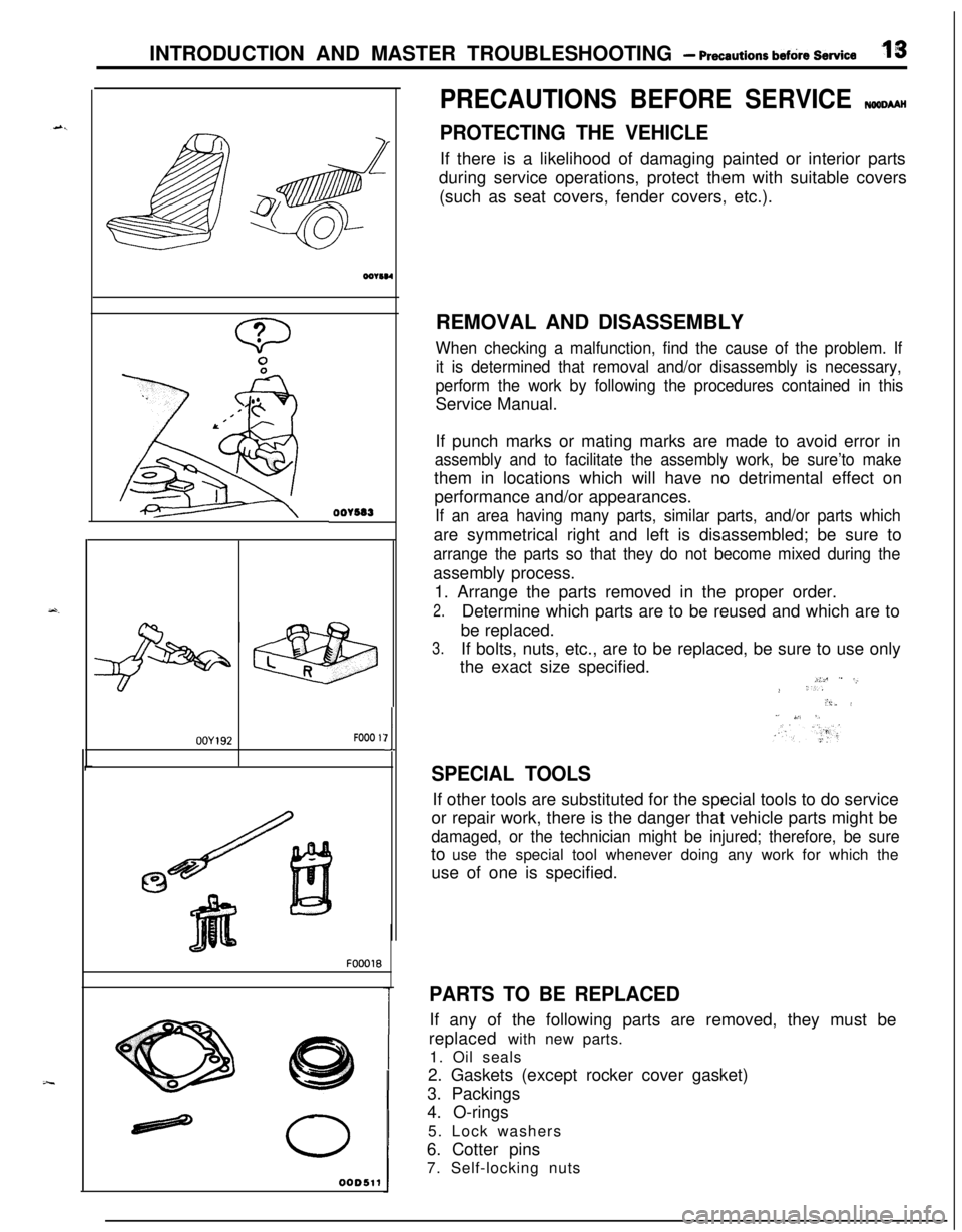
PROTECTING THE VEHICLEIf there is a likelihood of damaging painted or interior parts
during service operations, protect them with suitable covers
(such as seat covers, fender covers, etc.).
REMOVAL AND DISASSEMBLY
When checking a malfunction, find the cause of the problem. If
it is determined that removal and/or disassembly is necessary,
perform the work by following the procedures contained in thisService Manual.
If punch marks or mating marks are made to avoid error in
assembly and to facilitate the assembly work, be sure’to makethem in locations which will have no detrimental effect on
performance and/or appearances.
If an area having many parts, similar parts, and/or parts whichare symmetrical right and left is disassembled; be sure to
arrange the parts so that they do not become mixed during theassembly process.
1. Arrange the parts removed in the proper order.
2.Determine which parts are to be reused and which are to
be replaced.
3.If bolts, nuts, etc., are to be replaced, be sure to use only
the exact size specified.
i:c ” -,.> ‘..“i,. i” ,,‘. 5,
SPECIAL TOOLSIf other tools are substituted for the special tools to do service
or repair work, there is the danger that vehicle parts might be
damaged, or the technician might be injured; therefore, be sureto use the special tool whenever doing any work for which the
use of one is specified.
PARTS TO BE REPLACEDIf any of the following parts are removed, they must be
replaced with new parts.
1. Oil seals
2. Gaskets (except rocker cover gasket)
3. Packings
4. O-rings
5. Lock washers
6. Cotter pins
7. Self-locking nuts
Page 19 of 1216
c
--INTRODUCTION AND MASTER
TROUBLESHOOTtNG - Towing and Hoi&gT9
I-
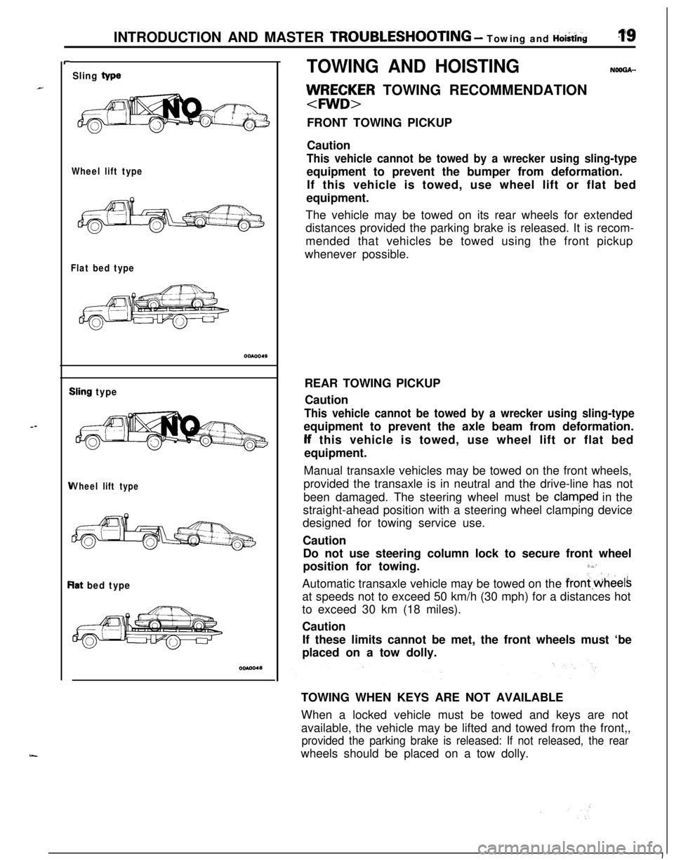
Sling type
Wheel lift type
Flat bed type
iling type
Vheel lift type
lat bed type
TOWING AND HOISTINGNOOGA-
llJ/RE;~R TOWING RECOMMENDATION
FRONT TOWING PICKUP
Caution
This vehicle cannot be towed by a wrecker using sling-typeequipment to prevent the bumper from deformation.
If this vehicle is towed, use wheel lift or flat bed
equipment.
The vehicle may be towed on its rear wheels for extended
distances provided the parking brake is released. It is recom-
mended that vehicles be towed using the front pickup
whenever possible.
REAR TOWING PICKUP
Caution
This vehicle cannot be towed by a wrecker using sling-typeequipment to prevent the axle beam from deformation.lf this vehicle is towed, use wheel lift or flat bed
equipment.
Manual transaxle vehicles may be towed on the front wheels,
provided the transaxle is in neutral and the drive-line has not
been damaged. The steering wheel must be
clam,ped in the
straight-ahead position with a steering wheel clamping device
designed for towing service use.
Caution
Do not use steering column lock to secure front wheel
position for towing.
3,“’Automatic transaxle vehicle may be towed on the
frontwheelsat speeds not to exceed 50 km/h (30 mph) for a distances hot
to exceed 30 km (18 miles).
Caution
If these limits cannot be met, the front wheels must ‘be
placed on a tow dolly.
TOWING WHEN KEYS ARE NOT AVAILABLE
When a locked vehicle must be towed and keys are not
available, the vehicle may be lifted and towed from the front,,
provided the parking brake is released: If not released, the rearwheels should be placed on a tow dolly.
I
Page 21 of 1216
--
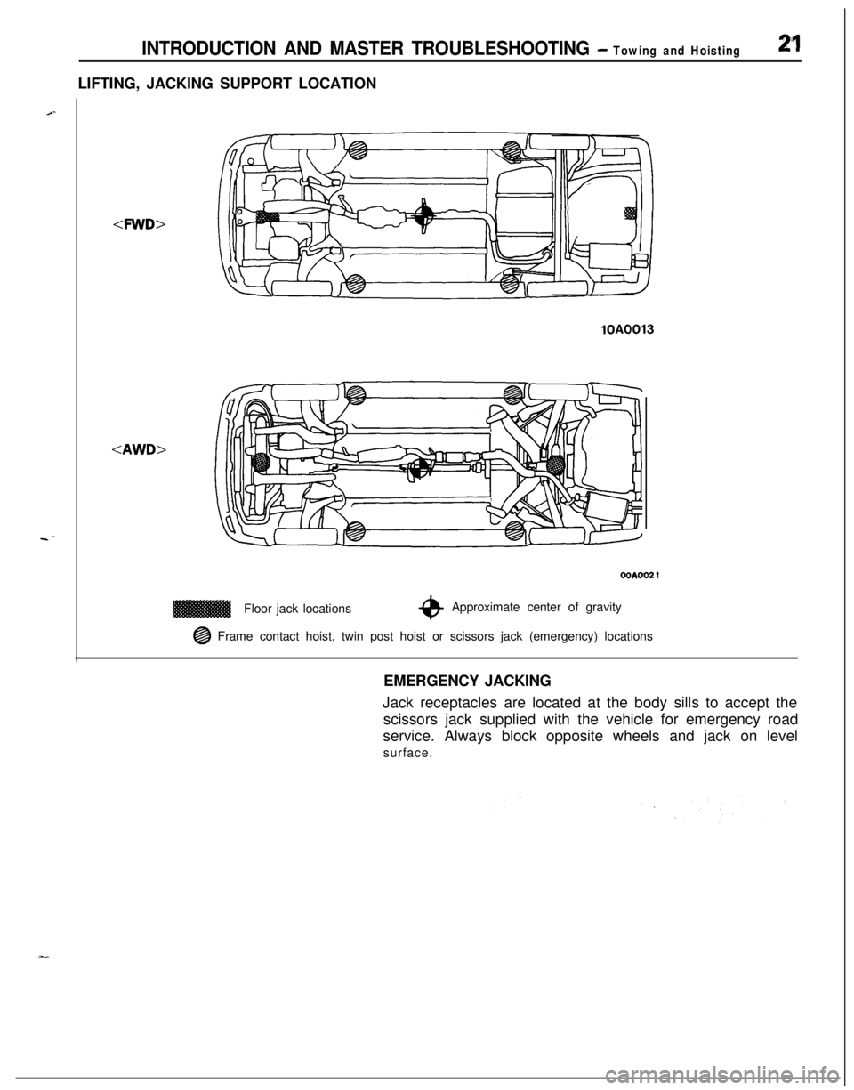
INTRODUCTION AND MASTER TROUBLESHOOTING - Towing and Hoisting2”1LIFTING, JACKING SUPPORT LOCATION
-4WD>
lOAFloor jack locations
OOAOO2 1
*Approximate center of gravity
@ Frame contact hoist, twin post hoist or scissors jack (emergency) locations
EMERGENCY JACKING
Jack receptacles are located at the body sills to accept the
scissors jack supplied with the vehicle for emergency road
service. Always block opposite wheels and jack on level
surface.
Page 28 of 1216
28INTRODUCTION AND MASTER TROUBLESHOOTING - Tightening Torque
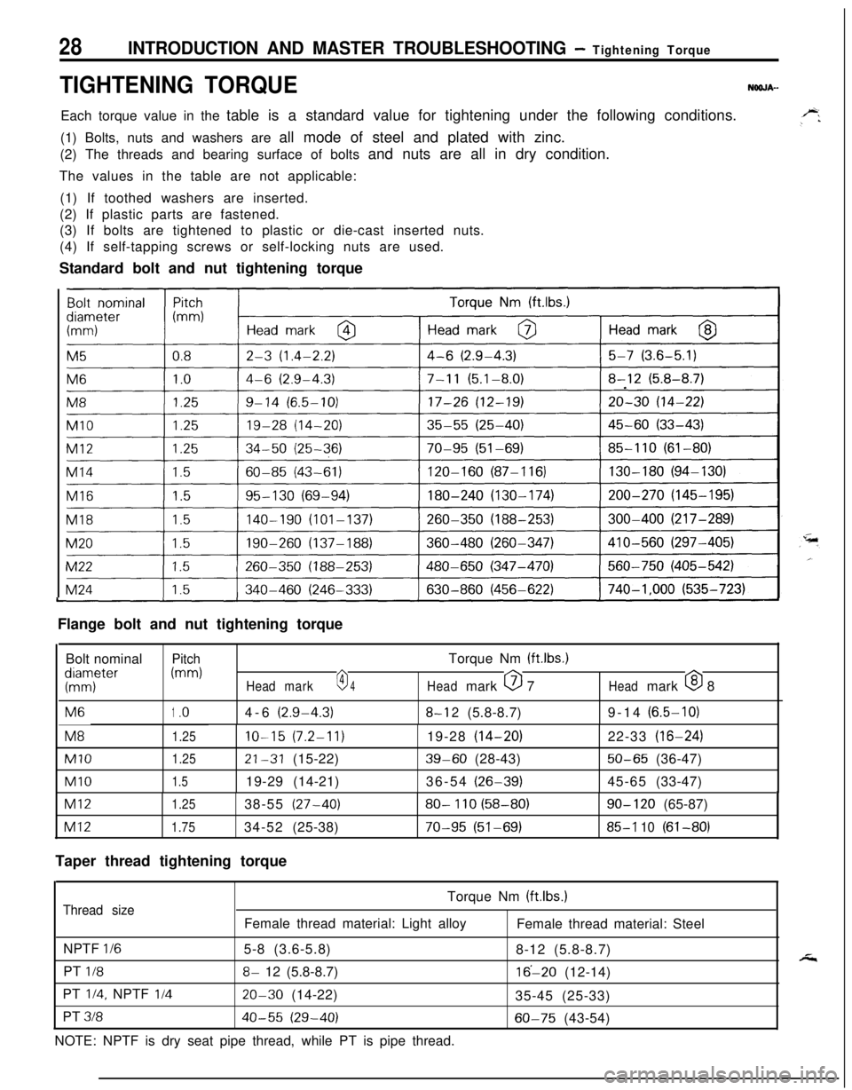
TIGHTENING TORQUENOOJA-Each torque value in the table is a standard value for tightening under the following conditions.
(1) Bolts, nuts and washers are all mode of steel and plated with zinc.
(2) The threads and bearing surface of bolts and nuts are all in dry condition.
The values in the table are not applicable:
(1) If toothed washers are inserted.
(2) If plastic parts are fastened.
(3) If bolts are tightened to plastic or die-cast inserted nuts.
(4) If self-tapping screws or self-locking nuts are used.
Standard bolt and nut tightening torque
I
I
ILFlange bolt and nut tightening torque
Bolt nominal
PitchTorque Nm (ftlbs.)
KTter
(mm)
Headmark0 4Headmark 0 7Headmark 0 8M6
1.o4-6(2.9-4.3)8-l 2(5.8-8.7)9-14(6.5-10)M8
1.25IO-15(7.2-11)19-28(14-20)22-33(16-24)
Ml01.2521-31(15-22)39-60(28-43)50-65(36-47)
Ml01.519-29(14-21)36-54(26-39)45-65(33-47)
Ml21.2538-55(27-40)80- 110 (58-80)90- 120(65-87)
Ml21.7534-52(25-38)70-95 (51-69)85-l 10(61-80)
Taper thread tightening torque
Torque Nm (ftlbs.)
Thread sizeFemale thread material: Light alloy
Female thread material: Steel
NPTF
l/65-8 (3.6-5.8)
8-12 (5.8-8.7)
PT
l/88- 12 (5.8-8.7)16’-20 (12-14)
PT
l/4, NPTF I/420-30 (14-22)
35-45 (25-33)
PT
31840-55 (29-40)60-75 (43-54)
NOTE: NPTF is dry seat pipe thread, while PT is pipe thread.
Page 38 of 1216
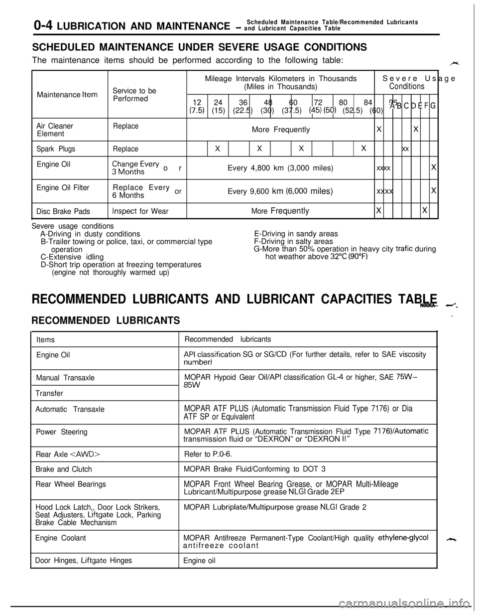
0-4 LUBRICATION AND MAINTENANCEScheduled Maintenance Table/Recommended Lubricants- and Lubricant Capacities TableSCHEDULED MAINTENANCE UNDER SEVERE USAGE CONDITIONS
The maintenance items should be performed according to the following table:
F.Mileage Intervals Kilometers in ThousandsSevere Usage
Service to be(Miles in Thousands)ConditionsMaintenance
Item
Performed24 36 48 60 72 80 84 96
(:,:) (15) (22.5) (30) (37.5) (45) (50) (52.5) (60) * B ’ D E F G
Air CleanerReplaceElementMore FrequentlyXX
Spark PlugsReplace
XXXx xx
Engine Oil$$~~~h~vev orEvery 4,800 km (3,000 miles)xxxx x
Engine Oil FilterReplace Every or6 MonthsEvery 9,600 km (6,000 miles)xxxx x
Disc Brake PadsInspect for WearMore FrequentlyXX
Severe usage conditionsA-Driving in dusty conditionsE-Driving in sandy areas
B-Trailer towing or police, taxi, or commercial typeF-Driving in salty areas
operationG-More than 50% operation in heavy city trafic during
C-Extensive idlinghot weather above 32°C (90°F)D-Short trip operation at freezing temperatures
(engine not thoroughly warmed up)
RECOMMENDED LUBRICANTS AND LUBRICANT CAPACITIES TABLENOONA- --z.
RECOMMENDED LUBRICANTS
Items
Engine Oil
Manual Transaxle
TransferRecommended lubricantskF&cesisification
SG or SG/CD (For further details, refer to SAE viscosity
MOPAR Hypoid Gear
Oil/API classification GL4 or higher, SAE 75W-85W
Automatic TransaxleMOPAR ATF PLUS (Automatic Transmission Fluid Type 7176) or Dia
ATF SP or Equivalent
Power SteeringMOPAR ATF PLUS (Automatic Transmission Fluid Type 7176VAutomatictransmission fluid or “DEXRON” or “DEXRON II”
Rear Axle
Brake and Clutch
Rear Wheel BearingsRefer to
P.O-6.
MOPAR Brake Fluid/Conforming to DOT 3
MOPAR Front Wheel Bearing Grease, or MOPAR Multi-MileageLubricant/Multipurpose grease NLGI Grade 2EP
Hood Lock Latch,, Door Lock Strikers,
Seat Adjusters, Lrftgate Lock, Parking
Brake Cable MechanismMOPAR Lubriplate/Multipurpose grease NLGI Grade 2
Engine CoolantMOPAR Antifreeze Permanent-Type Coolant/High quality
ethylene-glycolantifreeze coolant
Door Hinges, Liftgate Hinges
Engine oil
/
N
Page 44 of 1216
LUBRICATION AND MAINTENANCE - Maintenance Service
osFol2ENGINE
OIL FtLTER SELECTtONThis vehicle is equipped with a full-flow, throw-away oil
,~
filter.The same type of replacement filter is recommended as a
replacement filter for this vehicle. It is possible, particularilyin cold weather, that this vehicle may develop high oil
pressure for a short duration. You should be sure that any
replacement filter used on this vehicle is a high-quality filterand is capable of withstanding a pressure of 256 psi
(manufacturer’s specifications) to avoid filter and engine
damage. The following is a high-quality filter and is stronglyrecommended for use on this vehicle
: Mitsubishi Engine
-Oil Filter Part No. MD031805 or MD084693.
Any replacement oil filter should be installed in accordancewith the oil filter manufacturer’s installation instructions.
(1) Remove the engine oil filler cap.
(2) Remove the engine oil drain plug, and drain out the
engine oil.
(3) Remove the engine oil filter by using the oil filter
wrench.(4) Clean the oil filter mounting surface of the oil filter
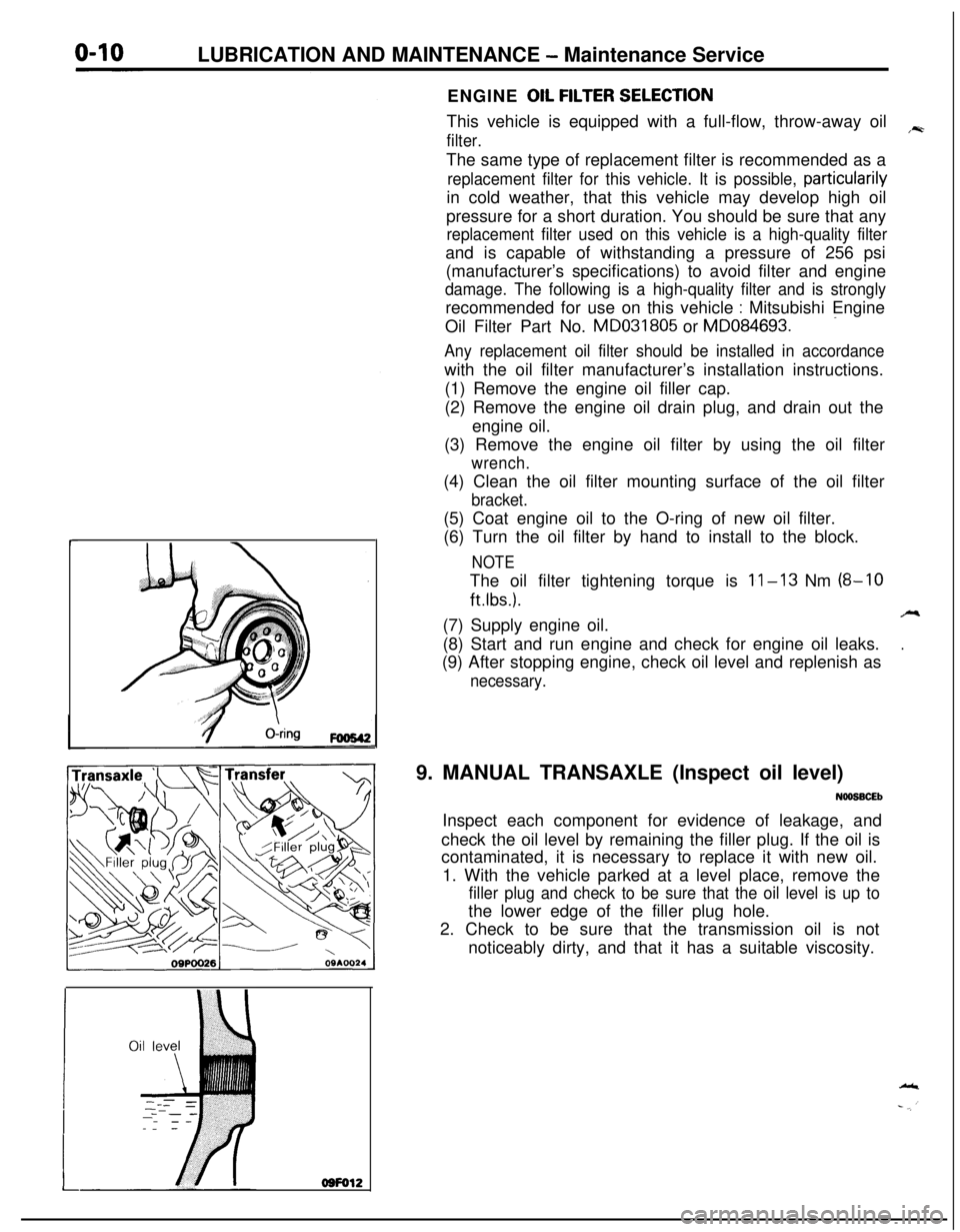
bracket.(5) Coat engine oil to the O-ring of new oil filter.
(6) Turn the oil filter by hand to install to the block.
NOTEThe oil filter tightening torque is
11-13 Nm (8-10
ftlbs.).A(7) Supply engine oil.
.(8) Start and run engine and check for engine oil leaks.
(9) After stopping engine, check oil level and replenish as
necessary.9. MANUAL TRANSAXLE (Inspect oil level)
NOOSBCEbInspect each component for evidence of leakage, and
check the oil level by remaining the filler plug. If the oil is
contaminated, it is necessary to replace it with new oil.
1. With the vehicle parked at a level place, remove the
filler plug and check to be sure that the oil level is up tothe lower edge of the filler plug hole.
2. Check to be sure that the transmission oil is not
noticeably dirty, and that it has a suitable viscosity.
Page 57 of 1216
FRONT SUSPENSION - service Adjustment Procedures/Hub and Knuckle2-9
3.For each half turn of the left and right tie rods, the toe-in willbe adjusted by 6 mm
(24 in.).
4. After making the adjustments, use a turning radius gauge
to confirm that the steering wheel turning angle is within
the standard value range. (Refer to GROUP 19-Service
Adjustment Procedures.)
WHEEL BEARING ADJUSTMENTN02FCM
Bearing preload is pre-set to the specified value by design andtherefore can not be adjusted.
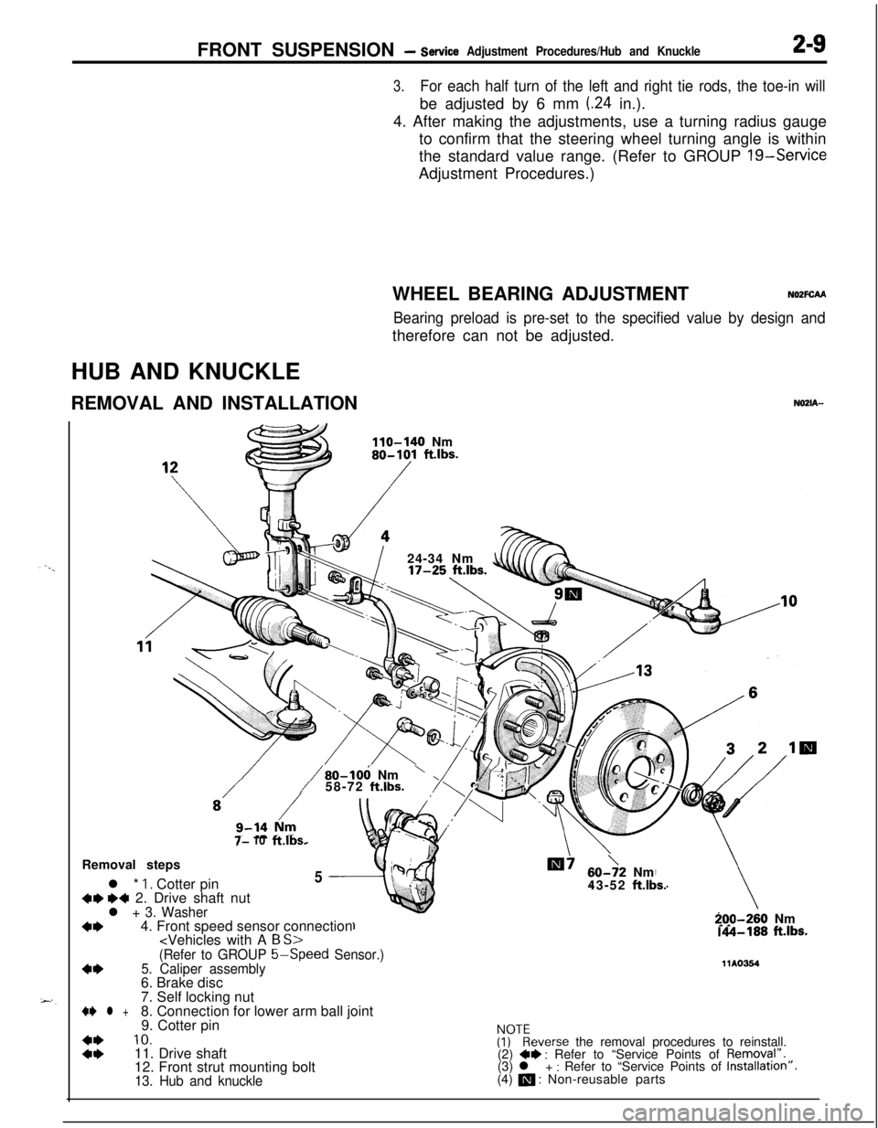
HUB AND KNUCKLE
REMOVAL AND INSTALLATION
NOZIA-
110-140 Nm80-101 ft.lbs.
/24-34 Nm
7- 10ft.lbs.
/80-106 Nm’58-72 ft.lbs.Removal steps
l *
1. Cotter pin5
+w ~~ 2. Drive shaft nutl + 3. Washer
+I)4. Front speed sensor connection
60->2 Nm
43-52 ft.lbs.
-70-260 Nm.A-188 ft.lbs.
(Refer to GROUP 5-Speed
Sensor.)
4*5. Caliper assembly11Ams46. Brake disc
7. Self locking nut
+e l +8. Connection for lower arm ball joint
9. Cotter pin
::
10.ivkeverse the removal procedures to reinstall.
11. Drive shaft
(2) +* : Refer to “Service Points of Removql”.
12. Front strut mounting bolt(3) l + : Refer to “Service Points of Installation”.
13. Hub and knuckle(4) a : Non-reusable parts
Page 64 of 1216
2-16FRONT SUSPENSION - Drive Shaft
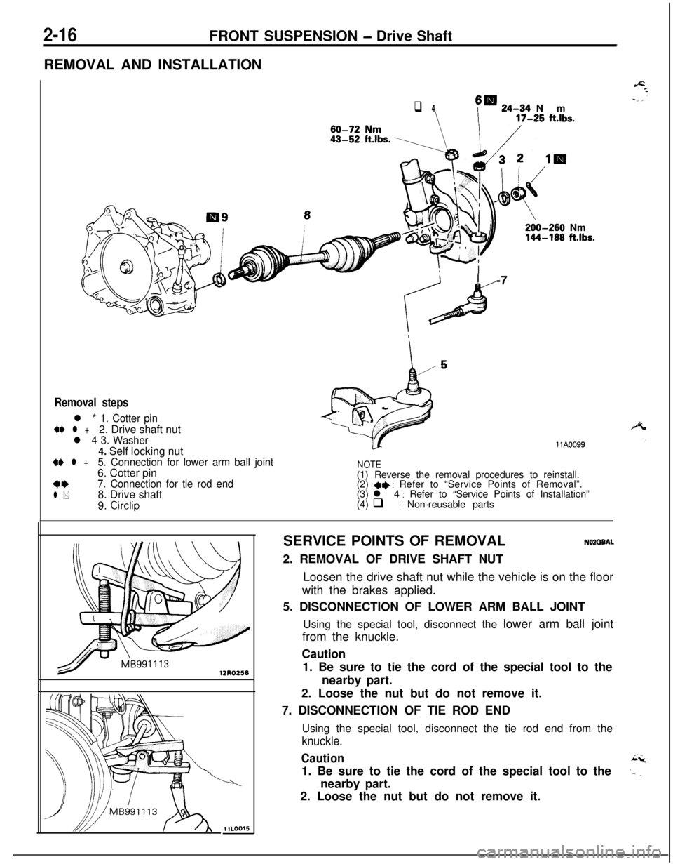
REMOVAL AND INSTALLATION
q 4sm 24-34 Nm
\ I17-25 ft.lbs.
/I200-260 Nm144-168 ftlbs.-7
Removal steps
l * 1. Cotter pin
4e l +2. Drive shaft nutl 4 3. Washer4. Self locking nut
+e l +5. Connection for lower arm ball joint6. Cotter pin
**7. Connection for tie rod end
l *8. Drive shaft
9. Circlip
llA0099
NOTE(1) Reverse the removal procedures to reinstall.
(2)
4* : Refer to “Service Points of Removal”.
(3) l 4 : Refer to “Service Points of Installation”
(4) q : Non-reusable parts
12130255
w
llLOO15SERVICE POINTS OF REMOVAL
NOZOBAL2. REMOVAL OF DRIVE SHAFT NUT
Loosen the drive shaft nut while the vehicle is on the floor
with the brakes applied.
5. DISCONNECTION OF LOWER ARM BALL JOINT
Using the special tool, disconnect the lower arm ball joint
from the knuckle.
Caution
1. Be sure to tie the cord of the special tool to the
nearby part.
2. Loose the nut but do not remove it.
7. DISCONNECTION OF TIE ROD END
Using the special tool, disconnect the tie rod end from the
knuckle.
Caution1. Be sure to tie the cord of the special tool to the
nearby part.
2. Loose the nut but do not remove it.