width MITSUBISHI ECLIPSE 1991 Service Manual
[x] Cancel search | Manufacturer: MITSUBISHI, Model Year: 1991, Model line: ECLIPSE, Model: MITSUBISHI ECLIPSE 1991Pages: 1216, PDF Size: 67.42 MB
Page 25 of 1216
INTRODUCTION AND MASTER TROUBLESHOOTING - :;k%ii::& and25
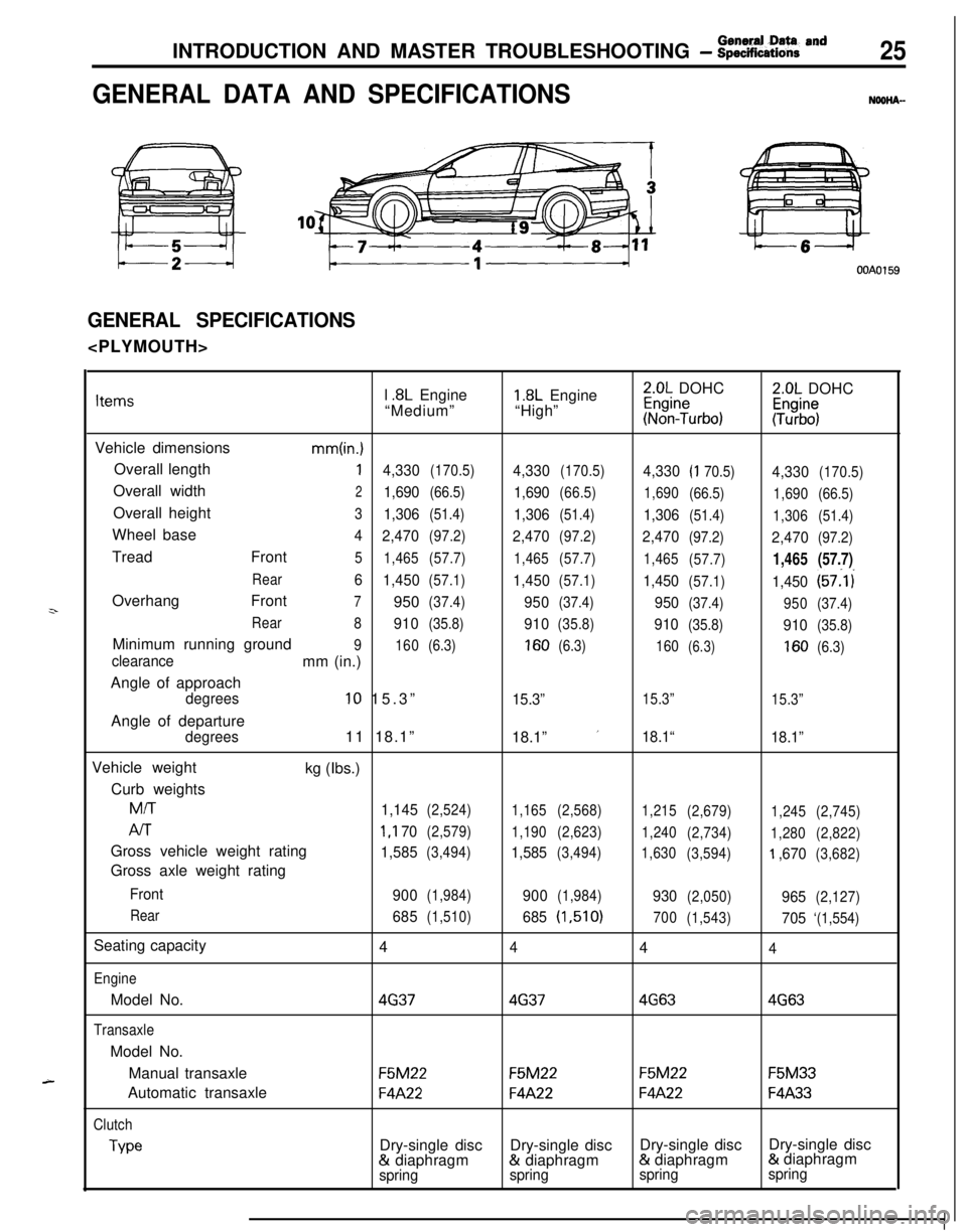
GENERAL DATA AND SPECIFICATIONSNOOHA-
OOAOl59
GENERAL SPECIFICATIONS
z-
A-l
.8L Engine1.8L Engine2.0L DOHC2.0L DOHCItems“Medium”“High”~%n?urbo):Tz%$
Vehicle dimensions
mm(in.)Overall length
14,330(170.5)4,330(170.5)4,330(I 70.5)4,330(170.5)Overall width
21,690(66.5)1,690(66.5)
1,690
(66.5)
1,690(66.5)Overall height
31,306(51.4)1,306(51.4)1,306(51.4)
1,306(51.4)Wheel base
4
2,470(97.2)2,470(97.2)2,470(97.2)2,470(97.2)Tread Front
5
1,465(57.7)
1,465(57.7)
1,465
(57.7)1,465(57.7)
Rear6
1,450(57.1)1,450(57.1)1,450(57.1)1,450(57:l i
Overhang Front
7950(37.4)950(37.4)950(37.4)
950(37.4)
Rear
8
910(35.8)910(35.8)910(35.8)910(35.8)Minimum running ground
9
160(6.3)160(6.3)
160(6.3)160(6.3)clearancemm (in.)
Angle of approach
degrees10 15.3”15.3”15.3”
15.3”Angle of departure
degrees11 18.1”
18.1” ’18.1“
18.1”Vehicle weight
kg (Ibs.)
Curb weights
M/T
1,145(2,524)
1,165(2,568)
1,215
(2,679)
1,245(2,745)
AIT1 ,I 70(2,579)
1,190(2,623)
1,240
(2,734)
1,280(2,822)Gross vehicle weight rating
1,585(3,494)1,585(3,494)
1,630
(3,594)‘I ,670(3,682)Gross axle weight rating
Front
900(1,984)900(1,984)930(2,050)965(2,127)
Rear
685(1,510)685(1,510)
700
(1,543)705‘(1,554)Seating capacity
4
444
EngineModel No.
4G3746374G634G63
TransaxleModel No.
Manual transaxle
F5M22F5M22F5M22F5M33Automatic transaxle
F4A22F4A22F4A22F4A33
Clutch
TypeDry-single discDry-single discDry-single discDry-single disc& diaphragm& diaphragm& diaphragm& diaphragm
springspringspringspring
Page 26 of 1216
26INTRODUCTION AND MASTER TROUBLESHOOTING - :;:%:a=and
Items
Chassis
TireFront suspension
TypeRear suspension
We
Brake
Type
SteeringGear typeFront
RearGear ratio
Fuel tank
Capacityliters (gals.)
1.8L Engine
“Medium”Pl85/70R14
PI 85/70Rl4
Independent
strut
Independentstrut
3l\Fk Torsion&k-k Torsion
Disc
DiscDisc
Disc
Rack and
pinion
03
Rack and
pinion
cn60 (16)
60
(16)
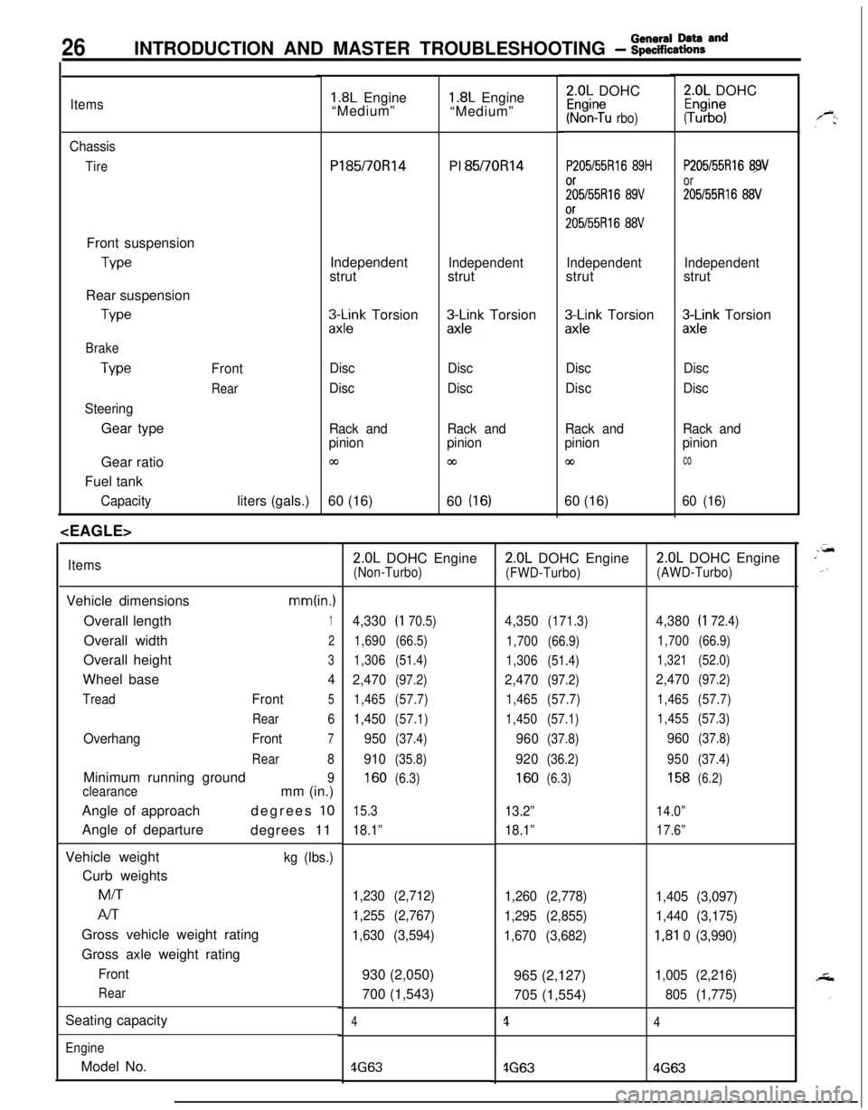
ItemsVehicle dimensions
mm(in.)Overall length
1Overall width
2Overall height
3Wheel base
4
TreadFront5
Rear6
OverhangFront7
Rear8Minimum running ground
9
clearancemm (in.)
Angle of approachdegrees
10Angle of departure
degrees 11
Vehicle weight
kg (Ibs.)Curb weightsMiT
Al-rGross vehicle weight rating
Gross axle weight rating
Front
RearSeating capacity
EngineModel No.
1.8L Engine
“Medium”2.0L DOHC
Kr%n?u rbo)
P205/55Rl6 89H
;;5/55R16 89V%55R16
88V
Independentstrut
zx;;k Torsion
Disc
Disc
Rack and
pinion
co60 (16)
2.0L DOHC
#b”;
P205/55Rl6 89
or
205155R16 88V
Independentstrut
3Lnk Torsion
Disc
Disc
Rack and
pinion
co
60 (16)
2.0L DOHC Engine(Non-Turbo)
4,330(I 70.5)
1,690(66.5)
1,306(51.4)
2,470(97.2)
1,465(57.7)
1,450(57.1)
950(37.4)
910(35.8)
160(6.3)
15.3
18.1”
1,230 (2,712)
1,255 (2,767)
1,630 (3,594)930 (2,050)
700 (1,543)
4
4G63
2.0L DOHC Engine
(FWD-Turbo)
4,350(171.3)
1,700(66.9)
1,306(51.4)
2,470(97.2)
1,465(57.7)
1,450(57.1)
960(37.8)
920(36.2)
160(6.3)
13.2”
18.1”
1,260 (2,778)
1,295 (2,855)
1,670 (3,682)965 (2,127)
705 (1,554)
1
4G63
2.0L DOHC Engine
(AWD-Turbo)
4,380(I 72.4)
1,700(66.9)
1,321(52.0)
2,470(97.2)
1,465(57.7)
1,455(57.3)
960(37.8)
950(37.4)
158(6.2)
14.0”
17.6”
1,405 (3,097)
1,440 (3,175)
I,81 0 (3,990)
1,005 (2,216)
805 (1,775)
4
4G63
Page 293 of 1216
ENGINE - SpecificationsItems
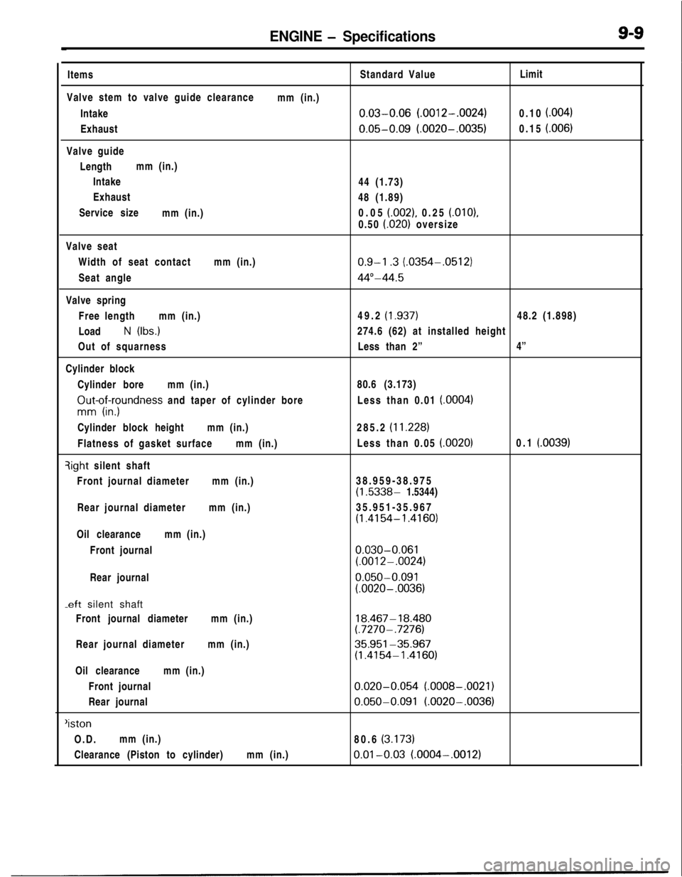
Valve stem to valve guide clearance
Intake
Exhaust
Valve guide
Lengthmm (in.)
Intake
Exhaust
Service size
mm (in.)mm (in.)Standard Value
0.03-0.06 (.0012-.0024)
0.05-0.09 (.0020-.0035)44 (1.73)
48 (1.89)
0.05
(.002), 0.25 (.OlO),
0.50
i.020) oversizeLimit
0.10
f.004)0.15
i.006)Valve seat
Width of seat contactmm (in.)
Seat angle
Valve spring
Free lengthmm (in.)
Load
N (Ibs.)
Out of squarness
Cylinder block
Cylinder boremm (in.)
ZIut-of;yundness and taper of cylinder bore
Cylinder block heightmm (in.)
Flatness of gasket surfacemm (in.)qight silent shaft
Front journal diametermm (in.)
Rear journal diametermm (in.)
Oil clearancemm (in.)
Front journal
Rear journal
-eft silent shaft
Front journal diametermm (in.)
Rear journal diametermm (in.)
Oil clearancemm (in.)
Front journal
Rear journal
‘istonO.D.mm (in.)
Clearance (Piston to cylinder)mm (in.)
0.9-l .3 (.0354-.0512)
44”-44.549.2
(1.937)48.2 (1.898)
274.6 (62) at installed height
Less than 2”4”
80.6 (3.173)
Less than 0.01
(.0004)285.2
(11.228)Less than 0.05
(.0020)0.1 (.0039)38.959-38.975
(1.5338- 1.5344)
35.951-35.967
(1.4154- 1.4160)
0.030-0.061(.0012-.0024)
0.050-0.091(.0020- .0036)
18.467- 18.480(.7270- .7276)
35.951-35.967(1.4154-1.4160)
0.020-0.054 (.0008-.0021)
0.050-0.091 (.0020-.0036)80.6
(3.173)
0.01-0.03 (.0004-.0012)
Page 295 of 1216
ENGINE - SDecifications9-11
.-ems
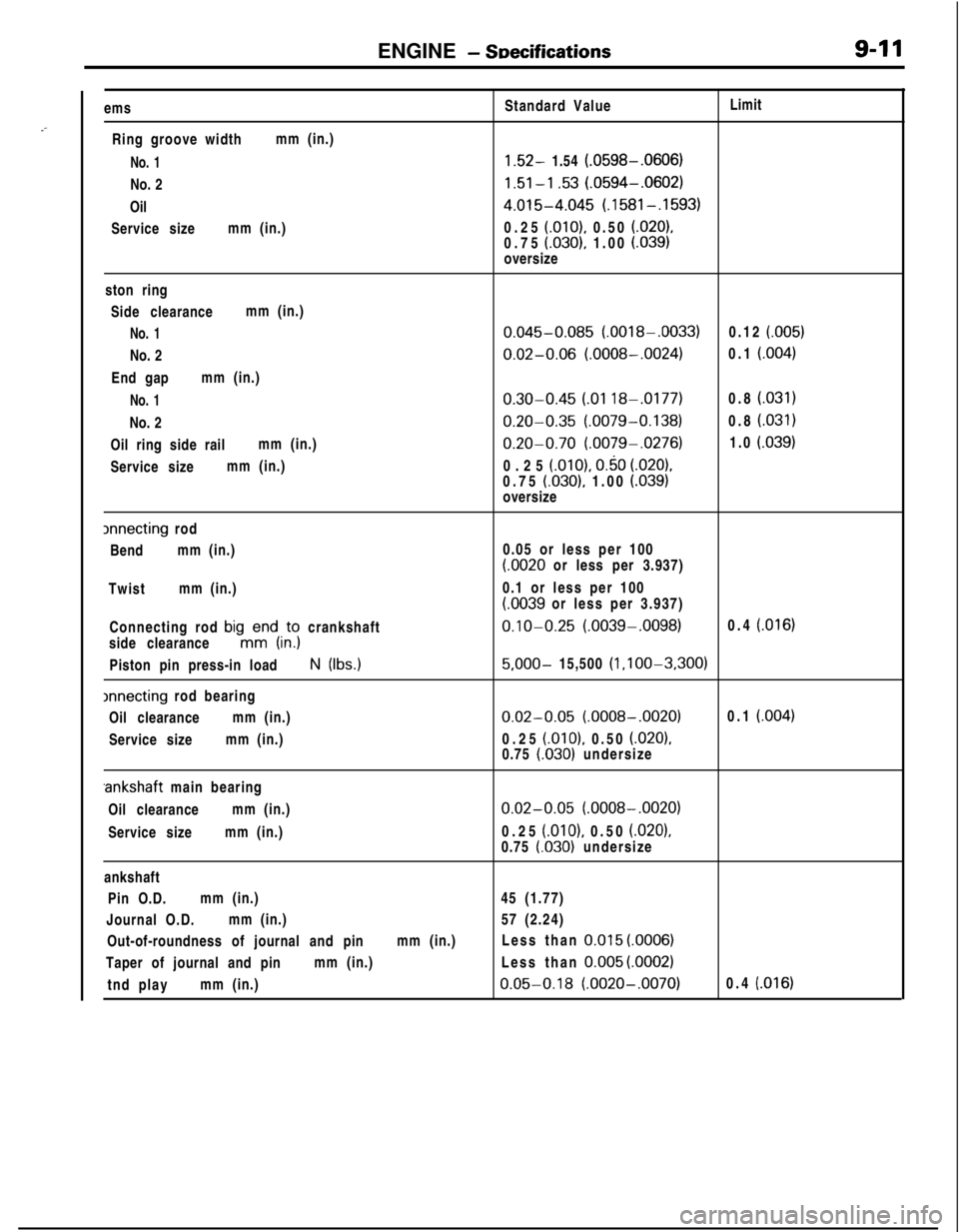
Ring groove widthmm (in.)
No. 1No. 2
Oil
Service sizemm (in.)Standard ValueLimit1.52- 1.54 (.0598-.0606)
1.51-l .53 (.0594-.0602)
4.015-4.045 (.1581-.1593)0.25
(.OlO), 0.50 (.020),0.75 (.030), 1.00 (.039)oversize
ston ring
Side clearancemm (in.)
No. 1No. 2
End gapmm (in.)
No. 1No. 2
Oil ring side railmm (in.)
Service sizemm (in.)
0.045-0.085 (.0018-.0033)0.12 (.005)
0.02-0.06 (.0008-.0024)0.1 (.004)
0.30-0.45 LO1 188.0177)0.8 (.031)
0.20-0.35 (.0079-0.138)0.8 i.031)
0.20-0.70 (.0079-.0276)1.0 (.039)0.25
(.OlO), 0.50 (.020).0.75 (.030), 1.00 LO391oversize
lnnecting rod
Bendmm (in.)
Twistmm (in.)
Connecting rod
bigmKdi,;; crankshaft
side clearance
Piston pin press-in loadN (Ibs.)
xrnecting rod bearing
Oil clearancemm (in.)
Service sizemm (in.)0.05 or less per 100
(.0020 or less per 3.937)
0.1 or less per 100
LOO39 or less per 3.937)
0.10-0.25 (.0039-.0098)0.4 (.016)
5,000- 15,500 (l ,l OO-3,300)
0.02-0.05 (.0008-.0020)0.1 (.004)0.25
(.OlO), 0.50 (.020),0.75 (.030) undersize.ankshaft main bearing
Oil clearancemm (in.)
Service sizemm (in.)
0.02-0.05 (.0008-.0020)0.25
(.OlO), 0.50 i.0201,
0.75 l.030) undersize
ankshaft
Pin O.D.mm (in.)45 (1.77)
Journal O.D.mm (in.)57 (2.24)
Out-of-roundness of journal and pinmm (in.)Less than
0.015 (.OOOS)Taper of journal and pinmm (in.)Less than
0.005 (.0002)tnd playmm (in.)
0.05-0.18 (.0020-.0070)0.4 (.016)
Page 298 of 1216
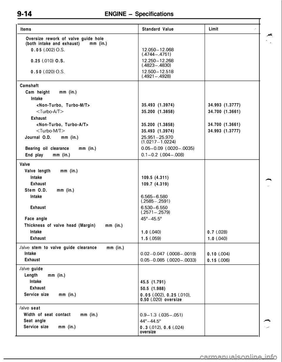
9-14ENGINE - SpecificationsItems
Oversize rework of valve guide hole
(both intake and exhaust)mm (in.)
0.05
(.002) O.S.0.25
(.OlO) O.S.
0.50
(.020) 0,s.Standard Value
12.050-12.068(.4744-.4751)
12.250-12.268(.4823-.4830)
12.500-12.518
(.4921-.4928)Limit
,’Camshaft
Cam heightmm (in.)
Intake
Exhaust
Journal O.D.mm (in.)
25.951-25.970(1.0217-1.0224)Bearing oil clearancemm (in.)
0.05-0.09 (.0020-.0035)End playmm (in.)
0.1-0.2 (.004-,008)Valve
Valve lengthmm (in.)
Intake
109.5 (4.311)
Exhaust
109.7 (4.319)
Stem O.D.mm (in.)
Intake
6.565-6.580(.2585-.2591)Exhaust
6.530-6.550
(.2571-.2579)Face angle
45"-45.5"Thickness of valve head (Margin)
mm (in.)
Intake
1.0
(.040)0.7 (.028)Exhaust
1.5
(.059)1.0 (.040)Jalve stem to valve guide clearance
mm (in.)
Intake
0.02-0.047 (.0008-.0019)0.10 (.004)Exhaust
0.05-0.085 (.0020-.0033)0.15 (.006)Jalve guide
Length
mm (in.)
Intake
45.5 (1.791)
Exhaust
50.5 (1.988)
Service size
mm (in.)
0.05
(.002), 0.25 (.OlO),0.50 (.020) oversize
/alve seat
Width of seat contact
mm (in.)
0.9-1.3 (.035-.051)Seat angle
44"-44.5"Service size
mm (in.)
0.3
(.012), 0.6 (.024)oversize
Page 299 of 1216
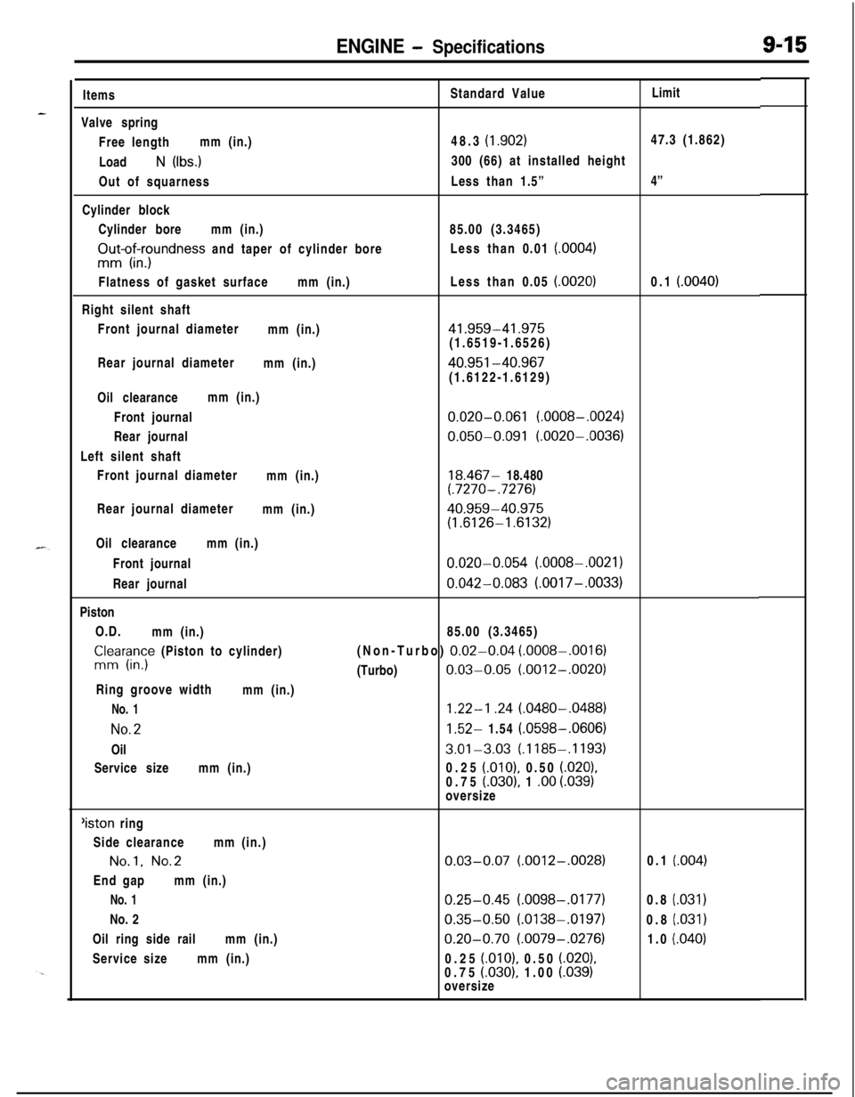
ENGINE - Specifications9-15ItemsStandard ValueLimit
Valve spring
Free lengthmm (in.)48.3
(1.902)47.3 (1.862)
Load
N (Ibs.)300 (66) at installed height
Out of squarnessLess than 1.5”4”
Cylinder block
Cylinder boremm (in.)85.00 (3.3465)
FIu-o$xrndness and taper of cylinder boreLess than 0.01 (0004)Flatness of gasket surfacemm (in.)Less than 0.05
(.0020)0.1 (.0040)Right silent shaft
Front journal diameter
mm (in.)
41.959-41.975(1.6519-1.6526)
Rear journal diameter
mm (in.)
40.951-40.967(1.6122-1.6129)
Oil clearancemm (in.)
Front journal
0.020-0.061 (.0008-.0024)Rear journal
0.050-0.091 (.0020-.0036)Left silent shaft
Front journal diameter
mm (in.)
18.467- 18.480(.7270-.7276)Rear journal diameter
mm (in.)
40.959-40.975
(1.6126-1.6132)Oil clearancemm (in.)
Front journal
0.020-0.054 (.0008-.0021)Rear journal
0.042-0.083 (.0017-.0033)Piston
O.D.
mm (in.)85.00 (3.3465)
CnlIr;;y (Piston to cylinder)(Non-Turbo) 0.02-0.04 (.0008-.0016)(Turbo)
0.03-0.05 (.0012-.0020)Ring groove width
mm (in.)
No. 11.22-l .24 (.0480-.0488)
No.21.52- 1.54 (.0598-.0606)Oil
3.01-3.03 (.1185-.1193)Service sizemm (in.)0.25
(.OlO), 0.50 (.020),0.75
(.030), 1 .oo i.039)oversize‘iston ring
Side clearancemm (in.)
No.1. No.2End gapmm (in.)
No. 1No. 2
Oil ring side railmm (in.)
Service sizemm (in.)
0.03-0.07 (.0012-.0028)
0.25-0.45 (.0098-.0177)
0.35-0.50 (.0138-.0197)
0.20-0.70 (.0079-.0276)0.25
(.OlO), 0.50 (.020),0.75 (030). 1.00 i.039)oversize0.1
(.004)0.8
(.031)0.8
(.031)1.0
(.040)
Page 328 of 1216
9-44ENGINE <1.8L Engine> - Timing Belt
Rubber
exposedTooth missing and
1 EN0002
Crankshaftsprocket “6
Crankshaft 6EN304
Spacer
Chamfered
6EN009
J
TiGGrnmarkCrankshaft
\vsprocket “B”(7) Abnormal wear on teeth.
Initial stage:
Canvas on load side tooth flank worn (Fluffy canvas
afibers, rubber gone and color changed to white, and
-unclear canvas texture)
Final stage:Canvas on load side tooth flank worn down and rubber
exposed (tooth width reduced)
(8) Missing tooth.
TENSIONER PULLEYTurn the pulleys to check for possible binding, excessive play,
and unusual noise. Replace the pulley if any of these defects is
evident.”
SERVICE POINTS OF INSTALLATION
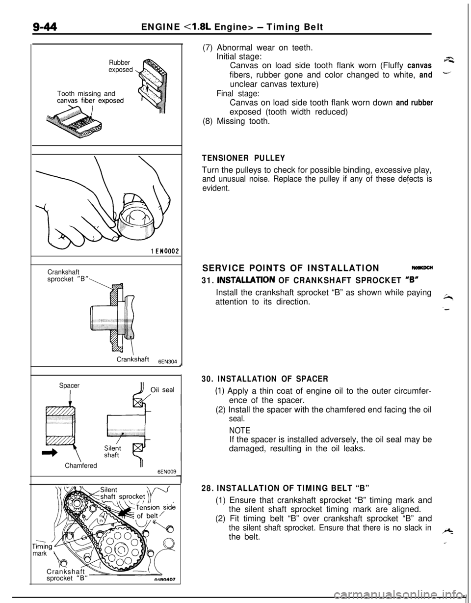
31. INSTALLATlON OF CRANKSHAFT SPROCKET “6”Install the crankshaft sprocket “B” as shown while paying
attention to its direction.
~,
‘d
30. INSTALLATION OF SPACER
(1) Apply a thin coat of engine oil to the outer circumfer-
ence of the spacer.
(2) Install the spacer with the chamfered end facing the oil
seal.
NOTEIf the spacer is installed adversely, the oil seal may be
damaged, resulting in the oil leaks.
28. INSTALLATION OF TIMING BELT “B”(1) Ensure that crankshaft sprocket “B” timing mark and
the silent shaft sprocket timing mark are aligned.
(2) Fit timing belt “B” over crankshaft sprocket “B” and
the silent shaft sprocket. Ensure that there is no slack inthe belt.+
a.
Page 348 of 1216
9-64ENGINE 4.8L Engine> -Front Case, Oil Pump and Silent Shaft
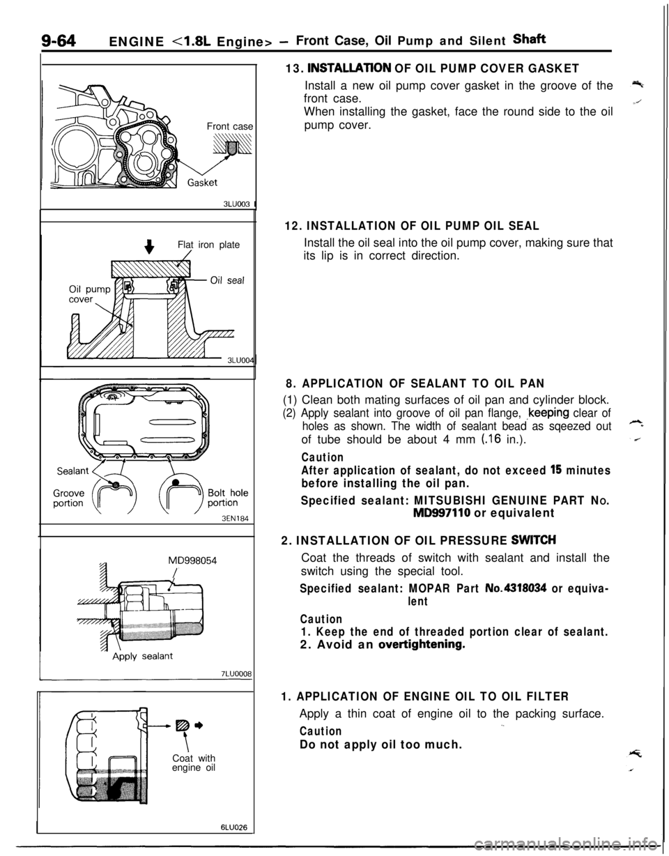
13.
INSTALLATlON OF OIL PUMP COVER GASKETInstall a new oil pump cover gasket in the groove of the
front case.
Front caseWhen installing the gasket, face the round side to the oil
pump cover.
3LUOO3 I
Flat iron plate
3EN184
MD998054
/
-----me
tCoat with
engine oil
6LUO26
12. INSTALLATION OF OIL PUMP OIL SEALInstall the oil seal into the oil pump cover, making sure that
its lip is in correct direction.
8. APPLICATION OF SEALANT TO OIL PAN(1) Clean both mating surfaces of oil pan and cylinder block.
(2) Apply sealant into groove of oil pan flange, ~keeping clear of
holes as shown. The width of sealant bead as sqeezed outof tube should be about 4 mm
(.I6 in.).
Caution
After application of sealant, do not exceed l’5 minutes
before installing the oil pan.
Specified sealant: MITSUBISHI GENUINE PART N
O.
MD997110 or equivalent
2. INSTALLATION OF OIL PRESSURE
SWlTCHCoat the threads of switch with sealant and install the
switch using the special tool.
Specified sealant: MOPAR Part No.4318034 or equiva-
lent
Caution
1. Keep the end of threaded portion clear of sealant.2. Avoid an
overtightening.
1. APPLICATION OF ENGINE OIL TO OIL FILTERApply a thin coat of engine oil to the packing surface.
,.Caution
Do not apply oil too much.
Page 354 of 1216
ENGINE <1.8L Engine> -Crankshaft, Flywheel and Drive Plate
3EN055
6EN043
1 EN067
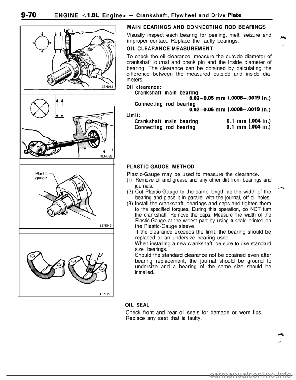
MAIN BEARINGS AND CONNECTING ROD BEARINGSVisually inspect each bearing for peeling, melt, seizure and
improper contact. Replace the faulty bearings.
OIL CLEARANCE MEASUREMENTTo check the oil clearance, measure the outside diameter of
crankshaft journal and crank pin and the inside diameter of
bearing. The clearance can be obtained by calculating the
difference between the measured outside and inside dia-
meters.
Oil clearance:
Crankshaft main bearing
0.02-0.05 mm (.OOOS-.0019 in.)
Connecting rod bearing
0.02-0.05 mm (.OOOS-.0019 in.)
Limit:
Crankshaft main bearing0.1 mm (.004 in.)
Connecting rod bearing0.1 mm (.004 in.)
PLASTIC-GAUGE METHODPlastic-Gauge may be used to measure the clearance.
(1)Remove oil and grease and any other dirt from bearings and
journals.(2) Cut Plastic-Gauge to the same length as the width of the
bearing and place it in parallel with the journal, off oil holes.(3) Install the crankshaft, bearings and caps and tighten them
to the specified torques. During this operation, do NOT turn
the crankshaft. Remove the caps. Measure the width of the
Plastic-Gauge at the widest part by using
a scale printed onthe Plastic-Gauge sleeve.
If the clearance exceeds the limit, the bearing should be
replaced or an undersize bearing used.
When installing a new crankshaft, be sure to use standard
size bearings.Should the standard clearance not be obtained even after
bearing replacement, the journal should be ground to
undersize and a bearing of the same size should be
installed.
OIL SEALCheck front and rear oil seals for damage or worn lips.
Replace any seat that is faulty.
Page 383 of 1216
ENGINE <2.0L DOHC Engine> - Timing Belt9-99
-
\
Q+i!il
008ooo
rackCrack
7EN207
SeparationRounded belt side
Abnormal wear
(fluffy canvas fiber)
7EN208
Rubber
exposedTooth missing and
canvas fiber
exoosed
7EN2096EN0159
-
INSPECTIONWSKCACTIMING BELTS
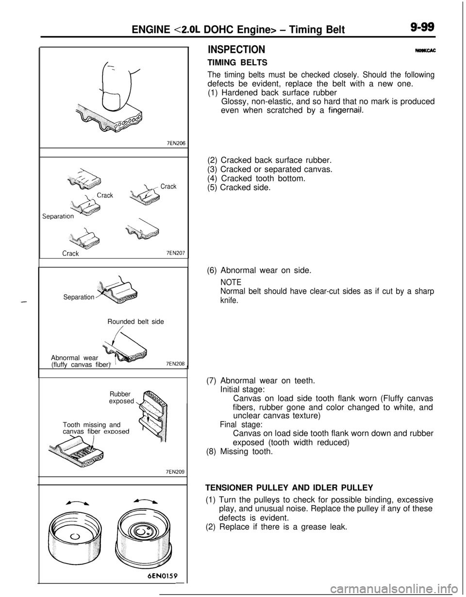
The timing belts must be checked closely. Should the followingdefects be evident, replace the belt with a new one.
(1) Hardened back surface rubber
Glossy, non-elastic, and so hard that no mark is produced
even when scratched by a
fingernai.1.(2) Cracked back surface rubber.
(3) Cracked or separated canvas.
(4) Cracked tooth bottom.
(5) Cracked side.J(6) Abnormal wear on side.
NOTE
Normal belt should have clear-cut sides as if cut by a sharp
knife.(7) Abnormal wear on teeth.
Initial stage:
Canvas on load side tooth flank worn (Fluffy canvas
fibers, rubber gone and color changed to white, and
unclear canvas texture)
Final stage:Canvas on load side tooth flank worn down and rubber
exposed (tooth width reduced)
(8) Missing tooth.
TENSIONER PULLEY AND IDLER PULLEY
(1) Turn the pulleys to check for possible binding, excessive
play, and unusual noise. Replace the pulley if any of these
defects is evident.
(2) Replace if there is a grease leak.