service MITSUBISHI ECLIPSE 1991 Service Manual
[x] Cancel search | Manufacturer: MITSUBISHI, Model Year: 1991, Model line: ECLIPSE, Model: MITSUBISHI ECLIPSE 1991Pages: 1216, PDF Size: 67.42 MB
Page 745 of 1216
MANUAL TRANSAXLE
I
2010x-
I. .I
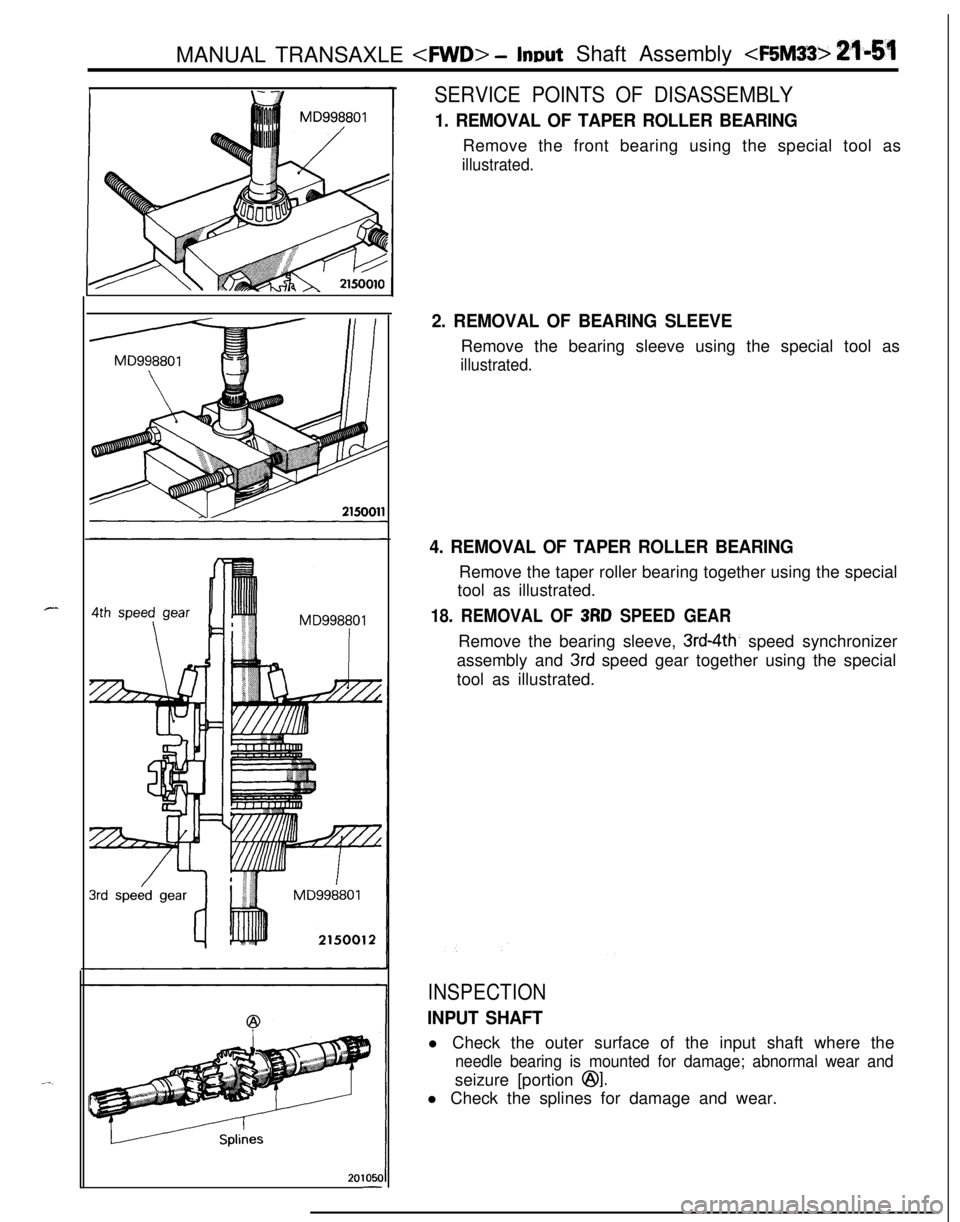
SERVICE POINTS OF DISASSEMBLY
1. REMOVAL OF TAPER ROLLER BEARINGRemove the front bearing using the special tool as
illustrated.
2. REMOVAL OF BEARING SLEEVERemove the bearing sleeve using the special tool as
illustrated.
4. REMOVAL OF TAPER ROLLER BEARINGRemove the taper roller bearing together using the special
tool as illustrated.
18. REMOVAL OF 3RD SPEED GEARRemove the bearing sleeve,
3rd-4th, speed synchronizer
assembly and
3rd speed gear together using the special
tool as illustrated.
INSPECTION
INPUT SHAFTl Check the outer surface of the input shaft where the
needle bearing is mounted for damage; abnormal wear andseizure [portion
@I.l Check the splines for damage and wear.
Page 747 of 1216
MANUAL TRANSAXLE
2010018
2ndgearTFM0024
MD998320
20105f
SPEED GEARS
lCheck the bevel gear and clutch gear teeth for damage andw.wear.l Check the synchronizer cone for rough surface, damage
and wear.
lCheck the gear bore and front and rear ends for damage
and wear.
SERVICE POINTS OF REASSEMBLY
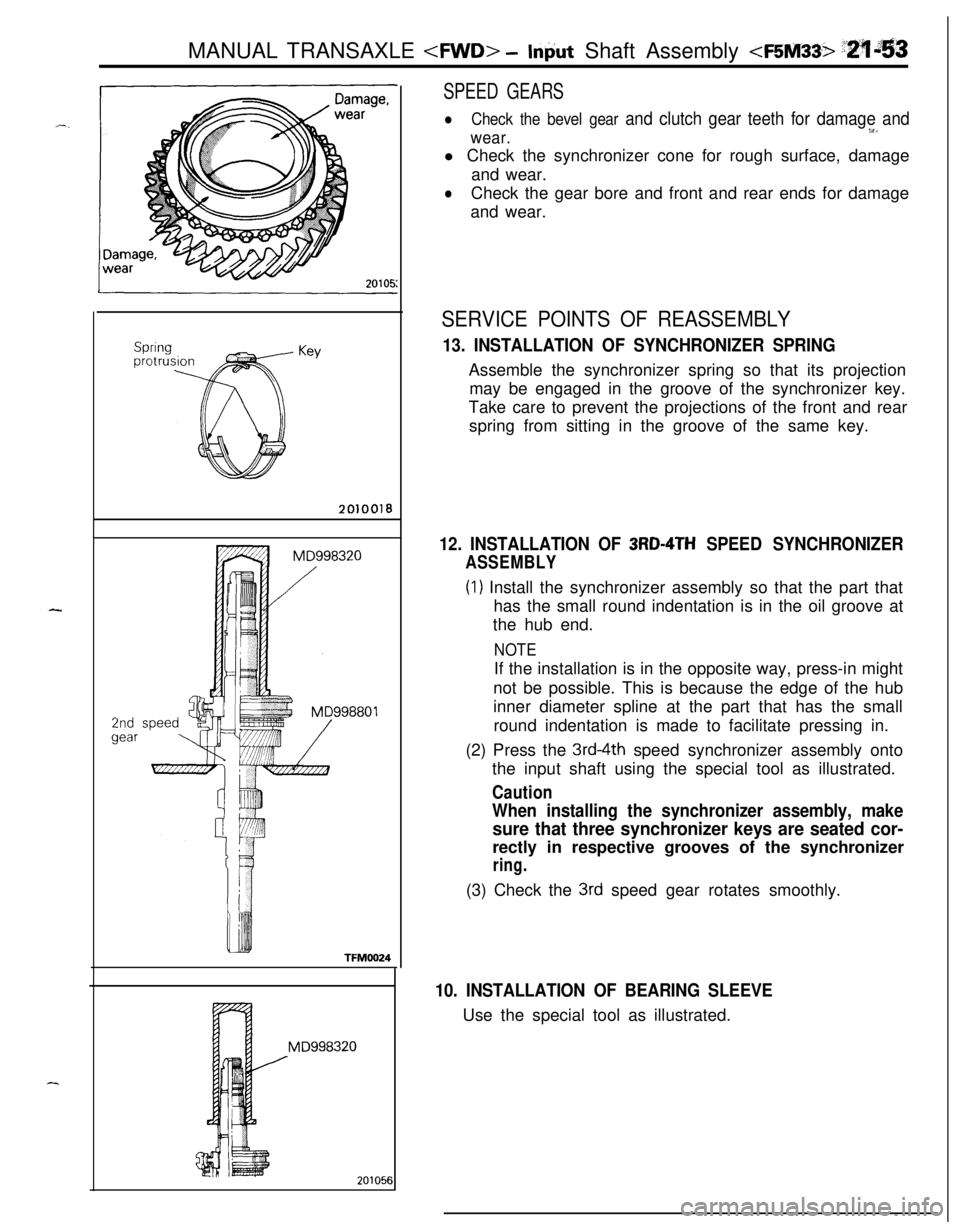
13. INSTALLATION OF SYNCHRONIZER SPRINGAssemble the synchronizer spring so that its projection
may be engaged in the groove of the synchronizer key.
Take care to prevent the projections of the front and rear
spring from sitting in the groove of the same key.
12. INSTALLATION OF 3RD-4TH SPEED SYNCHRONIZER
ASSEMBLY
(1) Install the synchronizer assembly so that the part that
has the small round indentation is in the oil groove at
the hub end.
NOTEIf the installation is in the opposite way, press-in might
not be possible. This is because the edge of the hub
inner diameter spline at the part that has the small
round indentation is made to facilitate pressing in.
(2) Press the
3rd-4th speed synchronizer assembly onto
the input shaft using the special tool as illustrated.
Caution
When installing the synchronizer assembly, make
sure that three synchronizer keys are seated cor-rectly in respective grooves of the synchronizer
ring.(3) Check the
3rd speed gear rotates smoothly.
10. INSTALLATION OF BEARING SLEEVEUse the special tool as illustrated.
j
Page 750 of 1216
21-56MANUAL TRANSAXLE
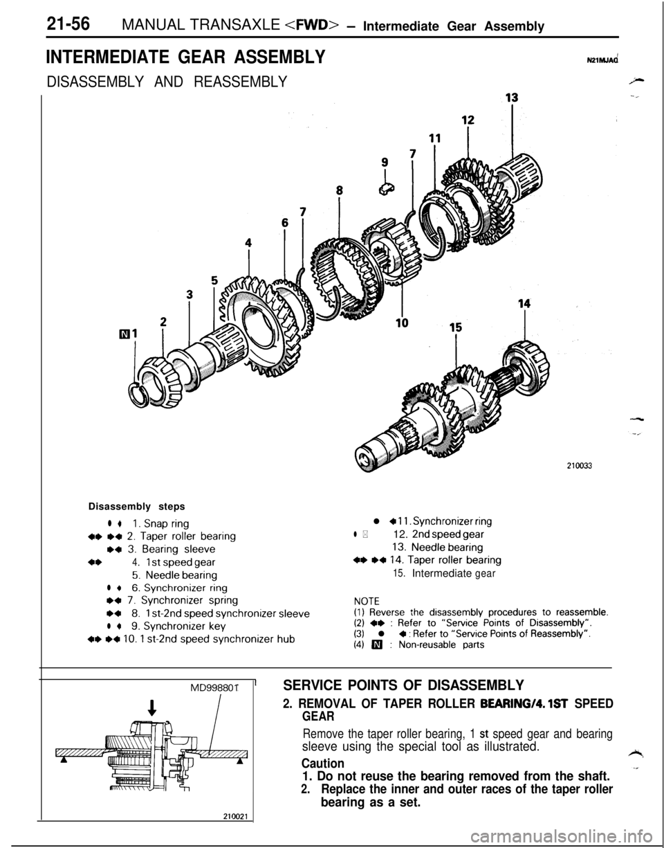
INTERMEDIATE GEAR ASSEMBLYNZlhlJAd
DISASSEMBLY AND REASSEMBLYDisassembly steps
l *1. Snap ring
w *+ 2. Taper roller bearing
w 3. Bearing sleeve
4*4.1 st speed gear
5.Needle bearing
l +6. Synchronizer ring
ea 7. Synchronizer spring
w8.1 st-2nd speed synchronizersleeve
l *9. Synchronizer key
+* ~~ 10. 1 st-2nd speed synchronizer hub
l a 11. Synchronizer ring
l *12. 2nd speed gear
13.Needle bearing
+* ,* 14. Taper roller bearing
15.Intermediategear
NOTE(1) Reverse the disassembly procedures to reassemble.(2) +e : Refer to “Service Points of Disassembly”.(3) l + : Refer to “Service Points of Reassembly”.
(4) III : Non-reusable parts
MD998801SERVICE POINTS OF DISASSEMBLY
2. REMOVAL OF TAPER ROLLER BEARING/Q. 1ST SPEED
GEAR
Remove the taper roller bearing, 1 st speed gear and bearing
sleeve using the special tool as illustrated.
Caution
1. Do not reuse the bearing removed from the shaft.
2.Replace the inner and outer races of the taper roller
bearing as a set.
Page 753 of 1216
MANUAL TRANSAXLE
.-_
Front +Identi-fication
mark
210031
Springprotrusion
Key2010018
SERVICE POINTS OF REASSElViBLY
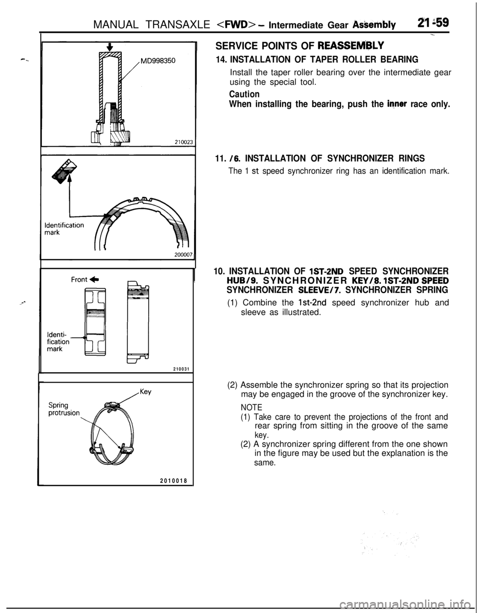
14. INSTALLATION OF TAPER ROLLER BEARINGInstall the taper roller bearing over the intermediate gear
using the special tool.
Caution
When installing the bearing, push the inner race only.
11. /6.
INSTALLATION OF SYNCHRONIZER RINGS
The 1 st speed synchronizer ring has an identification mark.
10. INSTALLATION OF lST-2ND SPEED SYNCHRONIZER
HUB/S. SYNCHRONIZER KEYi.8. IST-2ND SPEED
SYNCHRONIZER SLEEVE/7. SYNCHRONIZER SPRING(1) Combine the
lst-2nd speed synchronizer hub and
sleeve as illustrated.
(2) Assemble the synchronizer spring so that its projection
may be engaged in the groove of the synchronizer key.
NOTE
(1) Take care to prevent the projections of the front andrear spring from sitting in the groove of the same
key.(2) A synchronizer spring different from the one shown
in the figure may be used but the explanation is the
same.
Page 755 of 1216
MANUAL TRANSAXLE
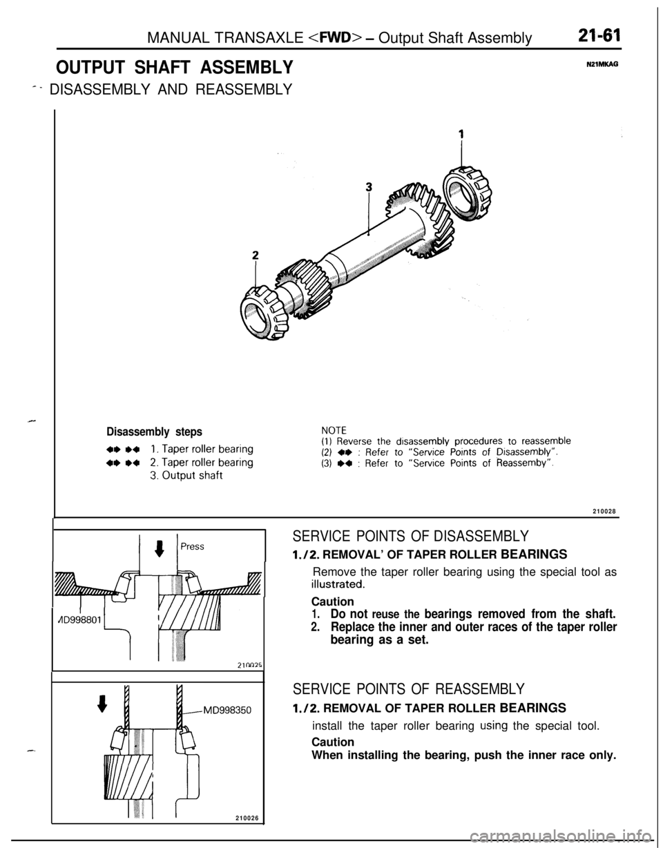
OUTPUT SHAFT ASSEMBLYNZlMKAG
# - DISASSEMBLY AND REASSEMBLY
.C
Disassembly steps
+* .+1. Taper roller bearing
4* w2. Taper roller bearing
3. Output shaft
NOTE
(I) Reverse the disassembly procedures to reassemble(2) +e : Refer to “Service Points of Disassembly”.
(3) W : Refer to “Service Points of Reassemby”.
210028
PressSERVICE POINTS OF DISASSEMBLY
1./2. REMOVAL’ OF TAPER ROLLER BEARINGS
Remove the taper roller bearing using the special tool as
illustrated.
AD9d880.l
il7inn75
I-. ----
MD998350
210026Caution
1.Do not reuse the bearings removed from the shaft.
2.Replace the inner and outer races of the taper roller
bearing as a set.
SERVICE POINTS OF REASSEMBLY
1./2. REMOVAL OF TAPER ROLLER BEARINGS
install the taper roller bearing
using the special tool.
Caution
When installing the bearing, push the inner race only.
Page 756 of 1216
21-62MANUAL TRANSAXLE
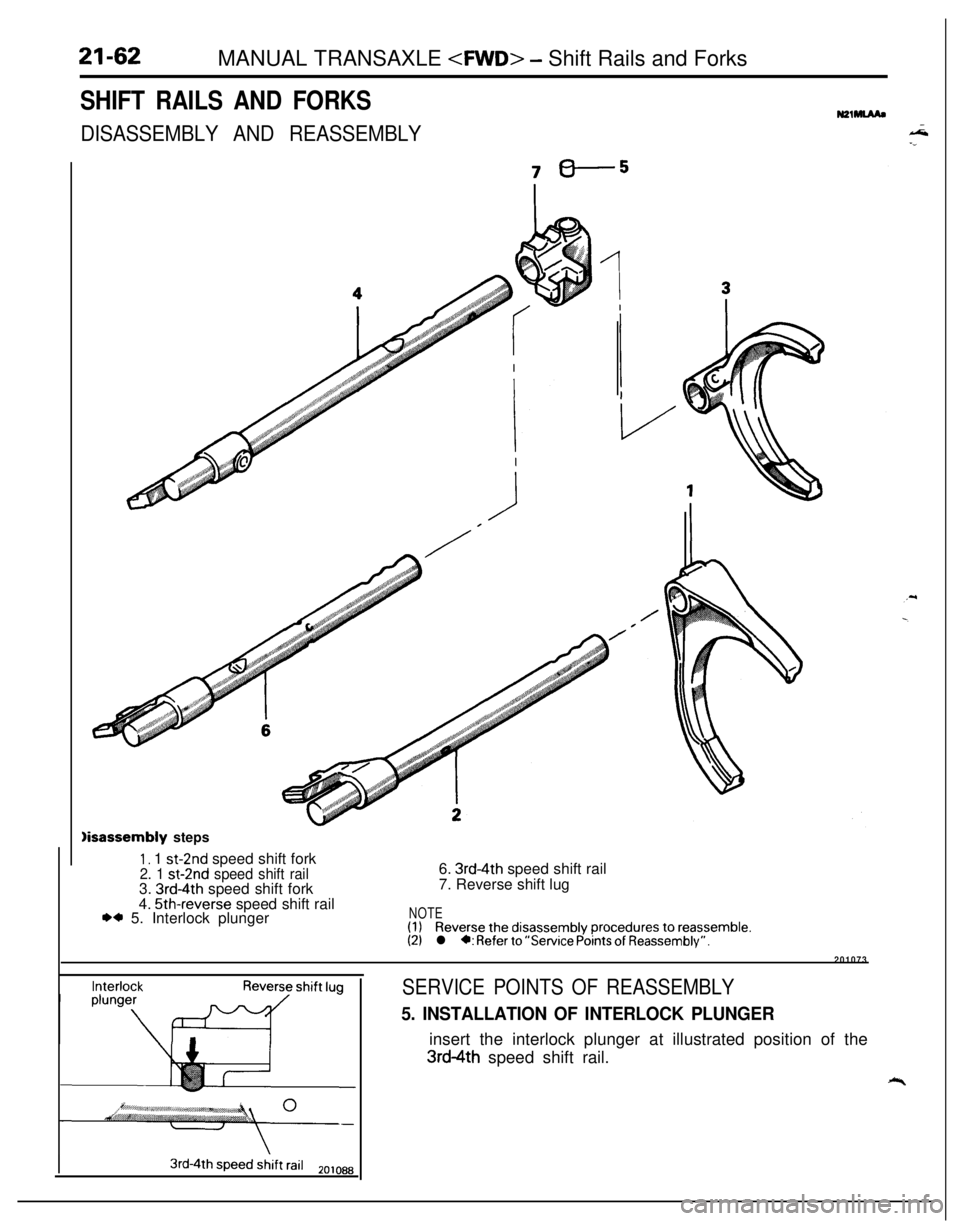
SHIFT RAILS AND FORKS
DISASSEMBLY AND REASSEMBLY
N21-
sbdisassembly steps
1, 1 st-2nd speed shift fork2. 1 st-2nd speed shift rail3. 3rd-4th speed shift fork
4. 5th-reverse speed shift rail** 5. Interlock plunger6.
3rd-4th speed shift rail
7. Reverse shift lug
NOTE(1)Reverse the disassembly procedures to reassemble.(2)l *: Refer to “Service Points of Reassembly”.
201073
InterlockReverse shift lugSERVICE POINTS OF REASSEMBLY
5. INSTALLATION OF INTERLOCK PLUNGERinsert the interlock plunger at illustrated position of the
3rd4th speed shift rail.
“r
3rd-4th speed shift rail2ojoaa
Page 757 of 1216
MANUAL TRANSAXLE 4WD> - Differential Assembly21-63
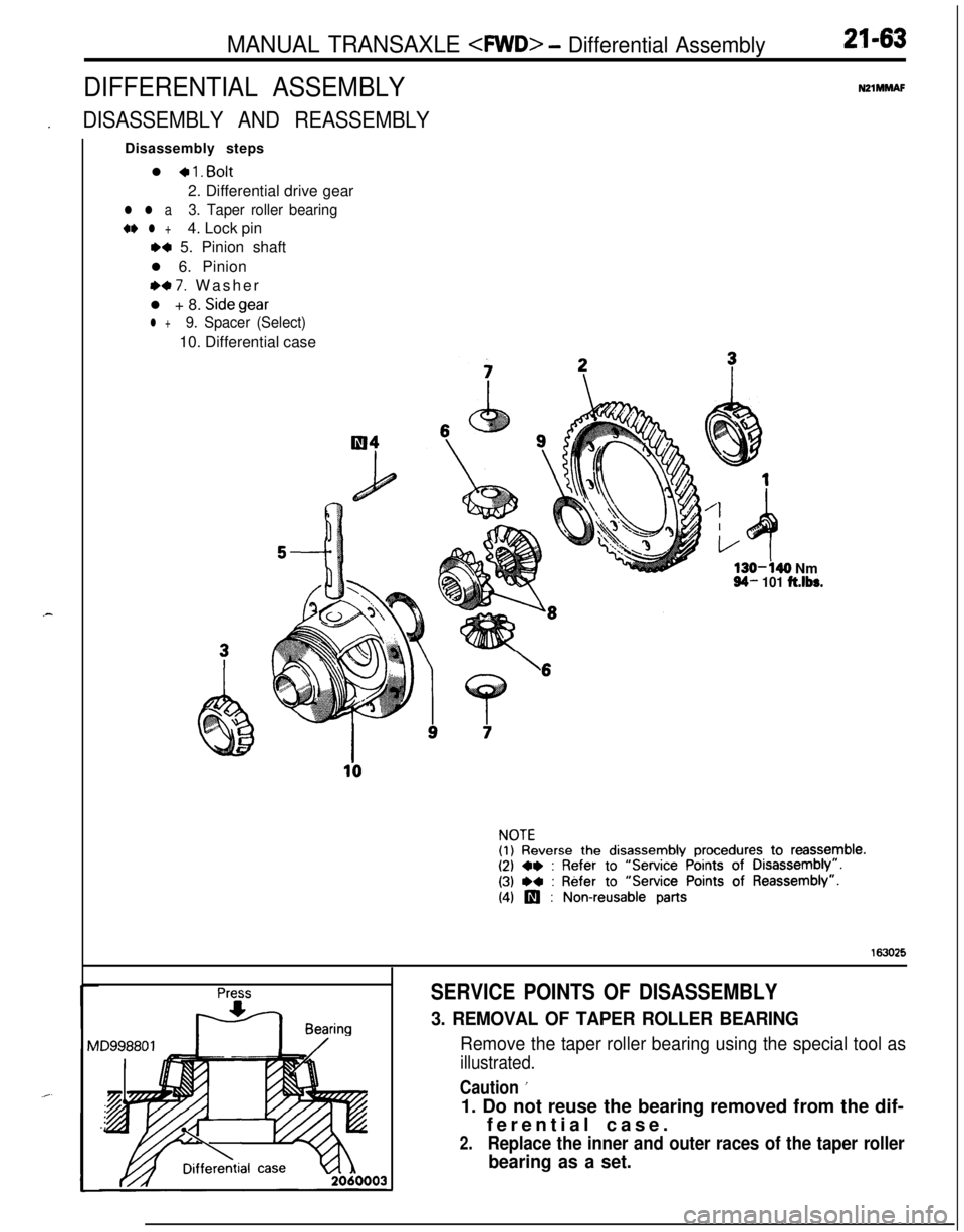
DIFFERENTIAL ASSEMBLYNZlMMAF.
DISASSEMBLY AND REASSEMBLYDisassembly steps
l
+ 1. Bolt2. Differential drive gear
l l a3. Taper roller bearing
+e l +4. Lock pin
M 5. Pinion shaft
l 6. Pinion
e+ 7. Washer
l + 8. Sidegear
l +9. Spacer (Select)10. Differential case
130-440 Nm94- 101 ft.lbs.
\6
NOTE(1) Reverse the disassembly procedures to reassemble.(2) ~~ : Refer to “Service Points of Disassembly”.
(3) ,+ : Refer to “Service Points of Reassembly”.
(4) p : Non-reusable parts
163025
Press
F+ Bearing
SERVICE POINTS OF DISASSEMBLY
3. REMOVAL OF TAPER ROLLER BEARING
Remove the taper roller bearing using the special tool as
illustrated.
Caution ’1. Do not reuse the bearing removed from the dif-
ferential case.
2.Replace the inner and outer races of the taper roller
bearing as a set.
Page 758 of 1216
21-64MANUAL TRANSAXLE
Lock pin
Llla
Lock pinDifferen-tial case
alla-ctiol
ock pinendwith2150021
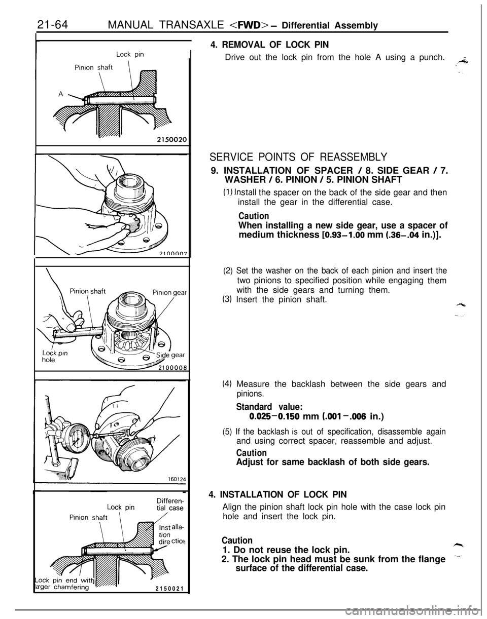
4. REMOVAL OF LOCK PINDrive out the lock pin from the hole A using a punch.
SERVICE POINTS OF REASSEMBLY9. INSTALLATION OF SPACER
/ 8. SIDE GEAR / 7.
WASHER
/ 6. PINION / 5. PINION SHAFT
(1) Install the spacer on the back of the side gear and then
install the gear in the differential case.
Caution
When installing a new side gear, use a spacer ofmedium thickness [0.93-1.00 mm (.36-.04 in.)].
(2) Set the washer on the back of each pinion and insert thetwo pinions to specified position while engaging
them
with the side gears and turning them.
(3) Insert the pinion shaft.
(4) Measure the backlash between the side gears and
pinions.
Standard value:0.025-0.150 mm
LOO1 -.006 in.)
(5) If the backlash is out of specification, disassemble againand using correct spacer, reassemble and adjust.
Caution
Adjust for same backlash of both side gears.
4. INSTALLATION OF LOCK PINAlign the pinion shaft lock pin hole with the case lock pin
hole and insert the lock pin.
Caution1. Do not reuse the lock pin.
2. The lock pin head must be sunk from the flange
surface of the differential case.
Page 759 of 1216
bierential Assembl /MANUAL TRANSAXLE
, .Bearing
TFYOOIO
The numerals 0 to (8 indicate1 the tiqhtening Gequeice.210029I
SPEEDOMETER GEAR ASSEMBLY
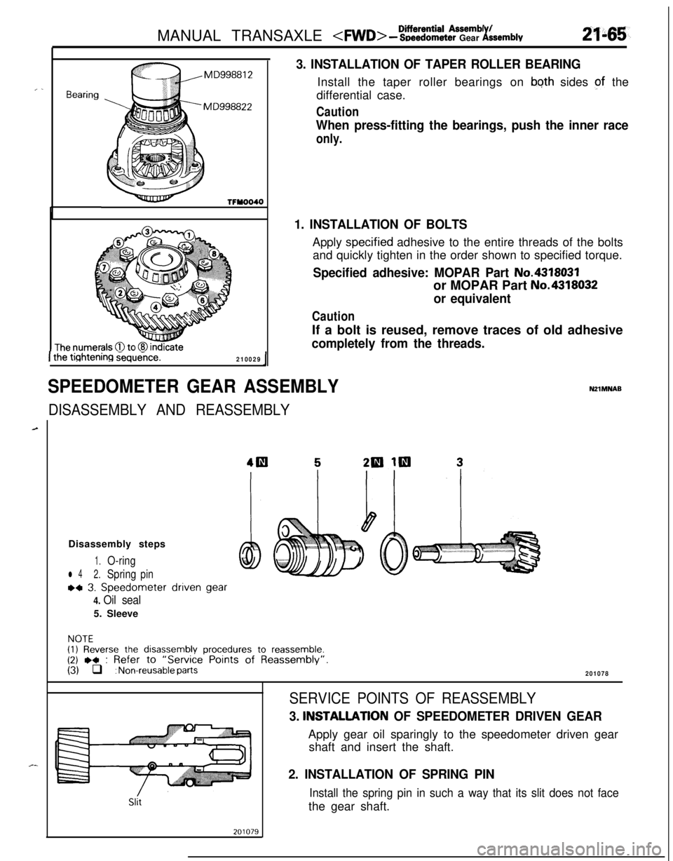
3. INSTALLATION OF TAPER ROLLER BEARINGInstall the taper roller bearings on
bqth sides of the
differential case.
Caution
When press-fitting the bearings, push the inner race
only.
1. INSTALLATION OF BOLTSApply
spec.ified adhesive to the entire threads of the bolts
and quickly tighten in the order shown to specified torque.
Specified adhesive: MOPAR Part No.4318031or MOPAR Part
No.4318032
or equivalent
CautionIf a bolt is reused, remove traces of old adhesive
completely from the threads.
DISASSEMBLY AND REASSEMBLY
NZlMNABDisassembly steps
1.O-ring
l 42.Springpin
~4 3. Speedometer driven gear
4. Oil seal5. Sleeve
NOTE(1) Reverse the disassembly procedures to reassemble.(2) ,+ : Refer to “Service Points of Reassembly”.(3) q : Non-reusable parts201078
Slit
SERVICE POINTS OF REASSEMBLY
3. INSTALLATlON OF SPEEDOMETER DRIVEN GEARApply gear oil sparingly to the speedometer driven gear
shaft and insert the shaft.
2. INSTALLATION OF SPRING PIN
Install the spring pin in such a way that its slit does not facethe gear shaft.
Page 760 of 1216
21-66MANUAL TRANSAXLE
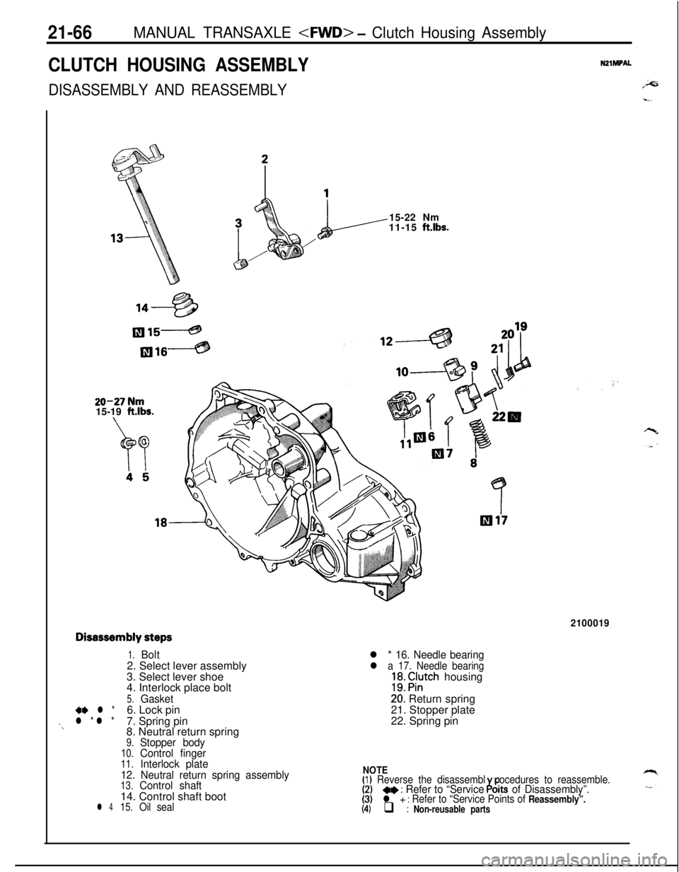
CLUTCH HOUSING ASSEMBLYNZlMPAL
DISASSEMBLY AND REASSEMBLY
2=
-,_
1
L--15-22 Nm
11-15 ftlbs.
20-27 Nm15-19 ft.lbs.
Disassembly steps
1.Bolt2. Select lever assembly
3. Select lever shoe
4. Interlock place bolt
5.Gasket+e l *6. Lock pinj\l * l *7. Spring pin
8. Neutral return spring
9.Stopper body10.Control finger11.Interlock plate
12. Neutral return spring assembly
13.Control shaft14. Control shaft boot
l 415.Oil seal
2100019
l * 16. Needle bearing
l a 17. Needle bearing;EJ. Fil;tch housing
20: Return spring
21. Stopper plate
22. Spring pin
NOTE(1) Reverse the disassembl procedures to reassemble.(2)~~ : Refer to “Service ornts of Disassembly”.6.(3)l + : Refer to “Service Points of Reassembly”.(4) q : Non-reusable parts