tow MITSUBISHI ECLIPSE 1991 Workshop Manual
[x] Cancel search | Manufacturer: MITSUBISHI, Model Year: 1991, Model line: ECLIPSE, Model: MITSUBISHI ECLIPSE 1991Pages: 1216, PDF Size: 67.42 MB
Page 949 of 1216
AUTOMATIC TRANSAXLE - Transaxle Assemblv
Spacer
1700108
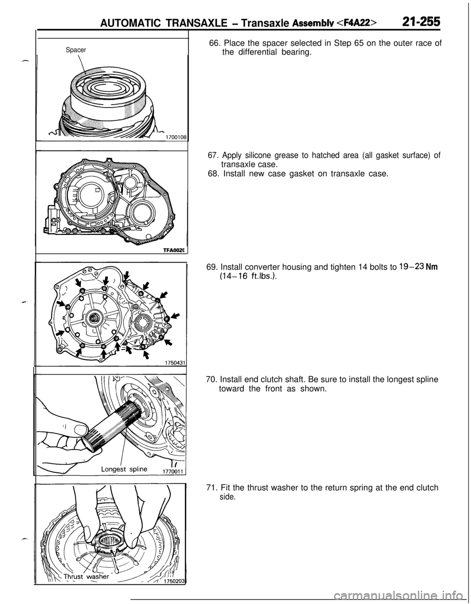
TFA002066. Place the spacer selected in Step 65 on the outer race of
the differential bearing.
67. Apply silicone grease to hatched area (all gasket surface) oftransaxle case.
68. Install new case gasket on transaxle case.
69. Install converter housing and tighten 14 bolts to
19-23 Nm
(14-16 ft.Ibs.).70. Install end clutch shaft. Be sure to install the longest spline
toward the front as shown.
71. Fit the thrust washer to the return spring at the end clutch
side.
Page 964 of 1216

-m-m AUTOMATIC TRANSAXLE -Transaxle Assembly
DISASSEMBLYN21WMCaution
%T1. Since the automatic transaxle is made of particularly
~_,high precision parts, be very careful when handling
them during disassembly and reassembly so that they
are not scratched.
2. Spread a rubber mat on the workbench and keep it
clean.3. Do not use cotton gloves or cloth rags during dis-
assembly. If they are needed, use nylon cloth or paper
towels.
4. Clean all disassembled parts. Clean metal
parts with
normal cleanser and completely dry with air.
5. Clean the clutch disc, resin thrust plate and rubber
parts with ATF (automatic transmission fluid) and do
not get any dirt on them.
6. If the transaxle itself is damaged, disassemble and
clean the cooler system also.
1. Remove the torque converter.
2. Mount the dial gauge on the transaxle case and measure
the end play of the input shaft.
3. Remove the brackets.
4. Remove the oil level gauge and oil level gauge guide.
1:5. Remove the pulse generator A and B.
6.First remove the manual control lever and then remove theinhibitor switch.
7. Remove the speedometer driven gear assembly.
Page 975 of 1216
AUTOMATIC TRANSAXLE - Transaxle Assembly
iWD (Front side)
MD998803
REASSEMBLYCautionNZlLFAO1. Do not reuse the gasket, O-ring, oil seal, etc. When
assembling, replace with new parts. (Note: The oil
level gauge rubber need not be replaced.)
2. Do NOT use any grease except petrolatum.
3. First apply ATF to the friction elements, the rotating
parts and sliding parts and then assemble.
Soak new clutch disc and brake disc in ATF for over 2
hours before using.
4. Do not use a sealing agent or adhesive agent on the
gaskets.
5.When replacing the bushing, replace the assembly that
includes the bushing.
6.Do not use cotton gloves or rags (cloth) when assemb-
ling. If required, use nylon cloth or paper towels.
7. Also replace the oil in the cooler.
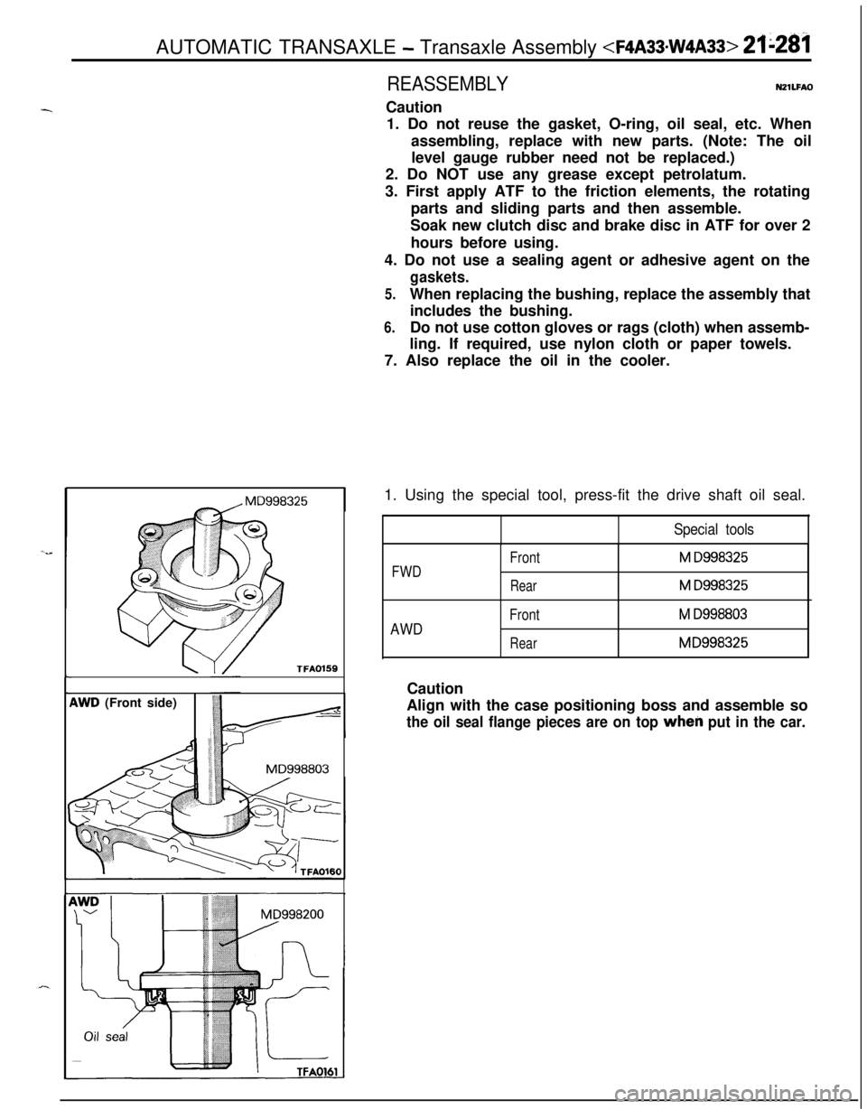
1. Using the special tool, press-fit the drive shaft oil seal.
Special tools
FWD
AWD
FrontM D998325
RearM D998325
Front
M D998803
RearMD998325Caution
Align with the case positioning boss and assemble so
the oil seal flange pieces are on top wheh put in the car.
Page 985 of 1216

AUTOMATIC TRANSAXLE - Transaxle Assembly
49. Install the clutch assembly and kickdown drum at the sametime in the transaxle case.
Thrust race
#3I50. Stick thrust race #3 and thrust washer #l to the rear end
of the oil pump with petrolatum.
51. Using the special tool, install a new oil pump gasket and oilpump assembly.
Oil pump assembly mounting bolts:
19-23 Nm (14-16
klbs.)52. Measure the input shaft end play and, if it is outside the
standard value, replace thrust race
#3 and thrust washer
#I and adjust so it reaches the standard value.
Standard value:
0.3-1.0 mm (.012-.039 in.)
53. Install the spacer, idler gear and bearing and then insert theidler shaft.
Caution
Install so the identification groove on the end of the
idler gear is toward the back side.
Page 1110 of 1216
23-66BODY - Door Trim and Waterproof Film/Door Glass and Regulator
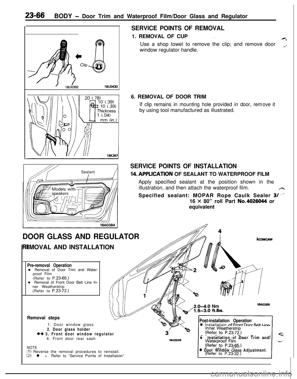
SERVICE POINTS OF REMOVAL1. REMOVAL OF CUP
‘.+iUse a shop towel to remove the clip; and remove door
_Awindow regulator handle.
IbY ISealant!I6. REMOVAL OF DOOR TRIM
If clip remains in mounting hole provided in door, remby using tool manufactured as illustrated.ove it
SERVICE POINTS OF INSTALLATION14,APPLlCATlON OF SEALANT TO WATERPROOF FILM
Apply specified sealant at the position shown in the
illustration, and then attach the waterproof film.
/rSpecified sealant: MOPAR Rope Caulk Sealer
3/ --‘I16
X 80” roll Part No.4026044 or
equivalent
DOOR GLASS AND REGULATORIMOVAL AND INSTALLATION
Pre-removal Operationl Removal of Door Trim and Water-
proof Film
(Refer to P.23-65.)
l Removal of Front Door Belt Line In-
ner Weatherstrip
(Refer to P.23-72.)
N23MCAW2.0-4-O
Nm1.5-3.0 ft.lbs.
Removal steps1. Door window glass
2. Door glass holder
*4 3. Front door window regulator
4. Front door rear sash
NOTEII ) Reverse the removal procedures to reinstall.12) l + : Refer to “Service Points of Installation”
Post-installation Operation0 Installation nf Frnnt lhnr Rnlt I inn
l Installation of Door Trim and
0 Door Window Glass Adjustment
Page 1121 of 1216
BODY - Sunroof2397
SUNROOFN22TTBAD
-- REMOVAL AND INSTALLATION
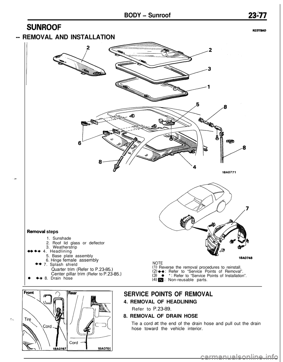
demoval steps
1. Sunshade
2. Roof lid glass or deflector
3. Weatherstrip
+w ++ 4. Headlining
5. Base plate assembly
6. Hinge female assembly
+* 7. Splash shield
Quarter trim (Refer to P.23-85.)Center pillar trim (Refer to P.23-85.)
l
++ 8. Drain hose
NOTE(I 1 Reverse the removal procedures to reinstall.(2) ** : Refer to “Service Points of Removal”.(3) l * : Refer to “Service Points of Installation”.(4) m : Non-reusable parts.
SERVICE POINTS OF REMOVAL4. REMOVAL OF HEADLINING
Refer to P.23-89.
8. REMOVAL OF DRAIN HOSE
Tie a cord
at the end of the drain hose and pull out the drain
hose toward the vehicle interior.
Page 1125 of 1216

BODY - Instrument Panel23-81
SECT. A-A
Flat-tip
( - ) screwdriver19A0274
1910267
SERVICE POINTS OF REMOVAL
10. REMOVAL OF CENTER AIR OUTLET ASSEMBLY
Removing the paw1 of the center air outlet assembly with aflat-tip
( - 1 screwdriver,remove the center air outlet
assembly with the plastic trim tool.
16. REMOVAL OF SPEEDOMETER CABLE ADAPTER
(1) Disconnect the speedometer cable at the transaxle endof the cable.
(2) Pull the speedometer cable slightly toward the vehicle
interior, release the lock by turning the adapter to the leftor right, and then remove the adapter.
Page 1132 of 1216
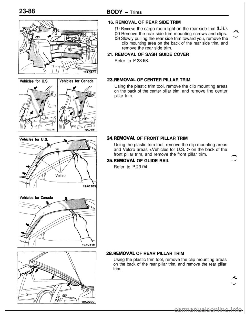
23-88BODY - Trims
Vehicles for U.S.Vehicles for CanadaI
I/IlQA028!
Vehicles for Ca16. REMOVAL OF REAR SIDE TRIM
(1) Remove the cargo room light on the rear side trim LH.).
(2) Remove the rear side trim mounting screws and clips.
(3) Slowly pulling the rear side trim toward you, remove the
clip mounting area on the back of the rear side trim, andremove the rear side trim.
21. REMOVAL OF SASH GUIDE COVER
Refer to
P.23-98.23.REMOVAL OF CENTER PILLAR TRIM
Using the plastic trim tool, remove the clip mounting areas
on the back of the center pillar trim, and remove the center
pillar trim.24.REMOVAL OF FRONT PILLAR TRIM
Using the plastic trim tool, remove the clip mounting areas
and Velcro areas
front pillar trim, and remove the front pillar trim.25.REMOVAL OF GUIDE RAIL
Refer to
P.23-94.28.REMOVAL OF REAR PILLAR TRIM
Using the plastic trim tool, remove the clip mounting areas
on the back of the rear pillar trim, and remove the rear pillar
trim.
Page 1174 of 1216
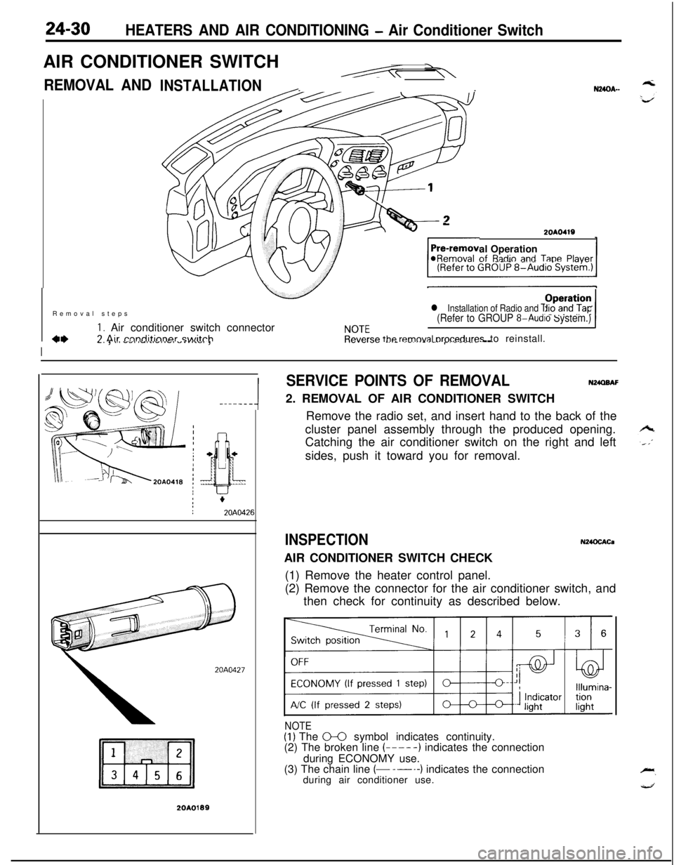
24-30HEATERS AND AIR CONDITIONING - Air Conditioner SwitchAIR CONDITIONER SWITCH
REMOVAL AND--N24OA..INSTALLATION
-2OAO419al Operationof
R;tdio and TanePlaver@Removal -..--._ _.-.-, -Removal steps
I. Air conditioner switch connectorCL7 Air rnnditinner switch
l Installation of Radio and Tape Player(Refer to GROUP 8-Audio System.)
NOTEOperation /Reverse
removal orocedures to reinstall.
I
77-. , .,a -.,a ,-,..-,.-. -.....,. ,.._._.__ _..- .-...-.-.r----- --
-----A
20A0427
20A0199
SERVICE POINTS OF REMOVALN24QBAF2. REMOVAL OF AIR CONDITIONER SWITCH
Remove the radio set, and insert hand to the back of the
cluster panel assembly through the produced opening.
Catching the air conditioner switch on the right and left
sides, push it toward you for removal.
INSPECTIONN24OCACaAIR CONDITIONER SWITCH CHECK
(1) Remove the heater control panel.
(2) Remove the connector for the air conditioner switch, and
then check for continuity as described below.
NOTE(1) The 0-0 symbol indicates continuity.
(2) The broken line (-----) indicates the connection
during ECONOMY use.
(3) The chain line
(- -----) indicates the connection
during air conditioner use.
Page 1180 of 1216
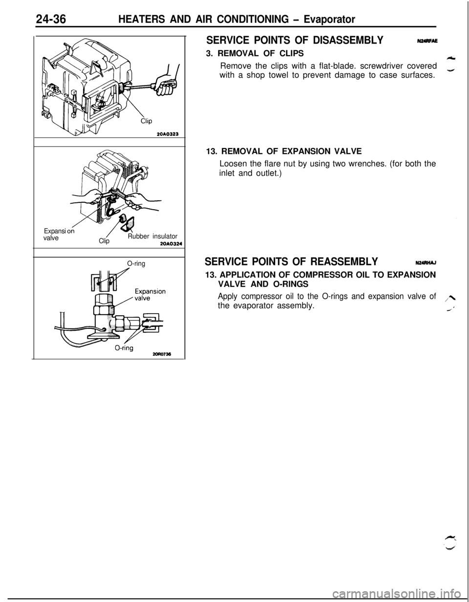
24-36HEATERS AND AIR CONDITIONING - Evaporator
SERVICE POINTS OF DISASSEMBLY3. REMOVAL OF CLIPS
N24nFAERemove the clips with a flat-blade. screwdriver covered
with a shop towel to prevent damage to case surfaces.
2OAO323
Expansivalve
ClipRubber insulator2OAO324
O-ring13. REMOVAL OF EXPANSION VALVE
Loosen the flare nut by using two wrenches. (for both the
inlet and outlet.)SERVICE POINTS OF REASSEMBLYN24nNAJ13. APPLICATION OF COMPRESSOR OIL TO EXPANSION
VALVE AND O-RINGS
Apply compressor oil to the O-rings and expansion valve ofthe evaporator assembly.