tow MITSUBISHI ECLIPSE 1991 Owner's Manual
[x] Cancel search | Manufacturer: MITSUBISHI, Model Year: 1991, Model line: ECLIPSE, Model: MITSUBISHI ECLIPSE 1991Pages: 1216, PDF Size: 67.42 MB
Page 498 of 1216
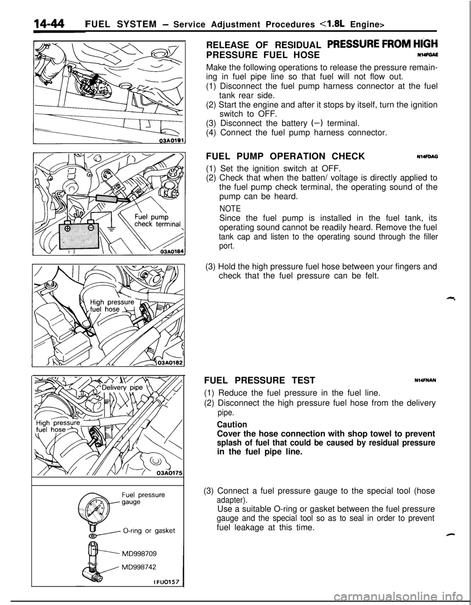
FUEL SYSTEM - Service Adjustment Procedures 4.8L Engine>
RELEASE OF RESIDUAL
PRESSURE FROM HIGHPRESSURE FUEL HOSE
N14FGAE
MD998709
MD998742
IFUO157Make the following operations to release the pressure remain-
ing in fuel pipe line so that fuel will not flow out.
(1) Disconnect the fuel pump harness connector at the fuel
tank rear side.
(2) Start the engine and after it stops by itself, turn the ignition
switch to OFF.
(3) Disconnect the battery
(-) terminal.
(4) Connect the fuel pump harness connector.
FUEL PUMP OPERATION CHECK
Nl4FDAG(1) Set the ignition switch at OFF.
(2) Check that when the batten/ voltage is directly applied to
the fuel pump check terminal, the operating sound of the
pump can be heard.
NOTESince the fuel pump is installed in the fuel tank, its
operating sound cannot be readily heard. Remove the fuel
tank cap and listen to the operating sound through the filler
port.(3) Hold the high pressure fuel hose between your fingers and
check that the fuel pressure can be felt.
FUEL PRESSURE TEST
Nl4FNAN(1) Reduce the fuel pressure in the fuel line.
(2) Disconnect the high pressure fuel hose from the delivery
pipe.
CautionCover the hose connection with shop towel to prevent
splash of fuel that could be caused by residual pressurein the fuel pipe line.
(3) Connect a fuel pressure gauge to the special tool (hose
adapter).Use a suitable O-ring or gasket between the fuel pressure
gauge and the special tool so as to seal in order to preventfuel leakage at this time.
-
Page 500 of 1216
14-46FUEL SYSTEM - Service Adjustment Procedures <1.8L Engine>
Condition
Fuel pressure too low
Fuel pressure too highProbable causea. Clogged fuel filter
b. Fuel leaking toward return port due to
Remedy
a. Replace fuel filter.
improper seating of valve in fuel pressure
b. Replace fuel pressure regulator.
regulatorc. Low delivery pressure of fuel pump
c. Replace fuel pump.
a. Stuck valve in fuel pressurea. Replace fuel pressure regulator.
regulator
b. Clogged or bent fuel return hose or pipeb. Repair or replace hose or pipe.
‘.
Fuel pressure witha. Clogged or broken vacuum hose or nipple
a. Repair or replace the vacuum hose or
vacuum hose connectednipple.
not different from fuel
pressure with vacuum
b. Stuck valve in fuel pressure regulator orb. Replace fuel pressure regulator.
hose not connecteddefective valve seating
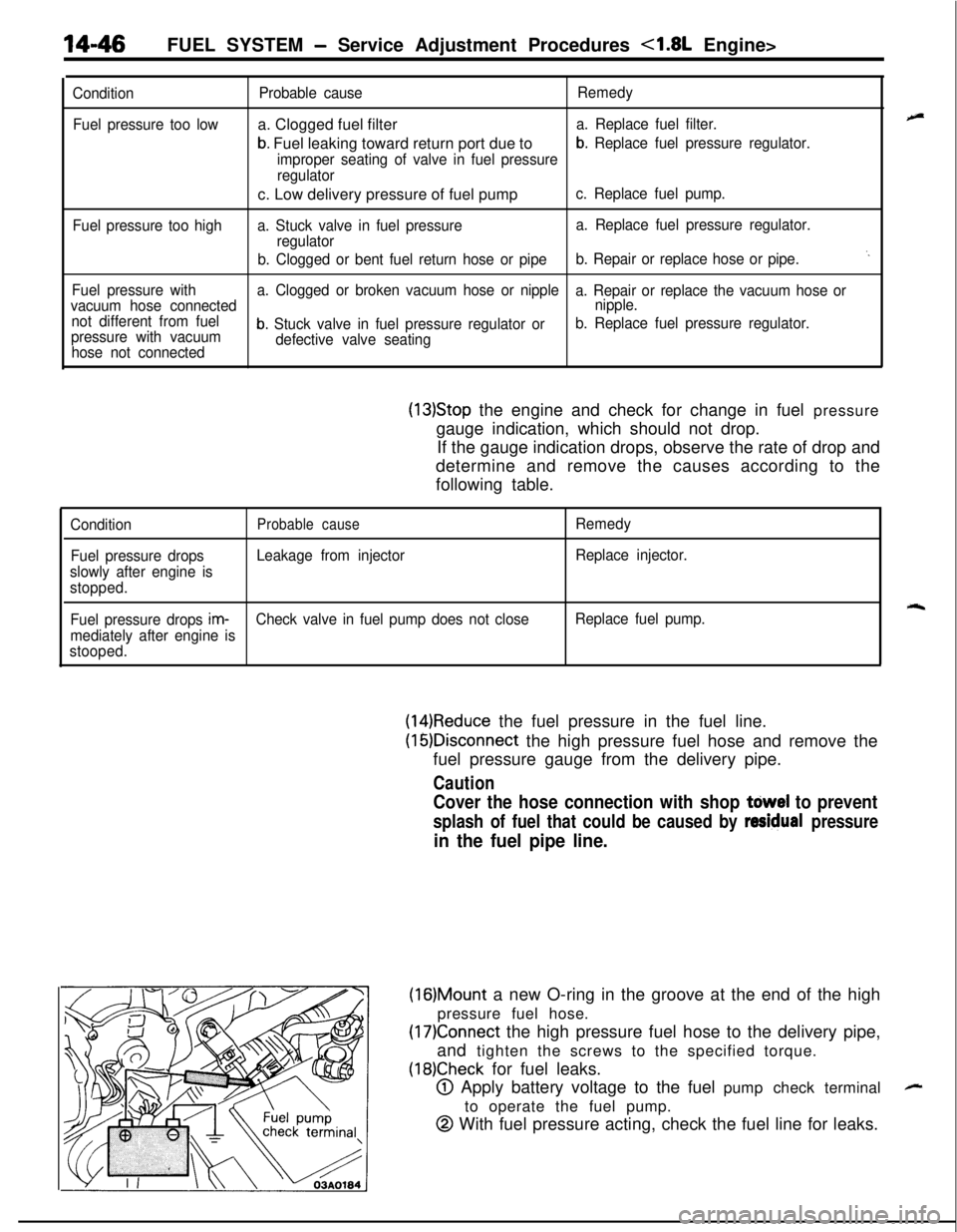
(13)Stop the engine and check for change in fuel pressure
gauge indication, which should not drop.
If the gauge indication drops, observe the rate of drop and
determine and remove the causes according to the
following table.
ConditionProbable causeRemedy
Fuel pressure dropsLeakage from injectorReplace injector.
slowly after engine is
stopped.
rqFuel pressure drops im-Check valve in fuel pump does not closeReplace fuel pump.
mediately after engine is
stooped.
(14)Reduce the fuel pressure in the fuel line.
(16)Disconnect the high pressure fuel hose and remove the
fuel pressure gauge from the delivery pipe.
Caution
Cover the hose connection with shop tdwel to prevent
splash of fuel that could be caused by residual pressure
in the fuel pipe line.
(16)Mount a new O-ring in the groove at the end of the high
pressure fuel hose.
(17)Connect the high pressure fuel hose to the delivery pipe,
and tighten the screws to the specified torque.
(18)Check for fuel leaks.
@ Apply battery voltage to the fuel pump check terminal
to operate the fuel pump.
@ With fuel pressure acting, check the fuel line for leaks.
-
Page 506 of 1216
14-52FUEL SYSTEM - Service Adjustment Procedures <2.0L Engine>
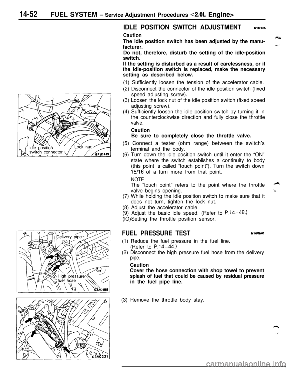
IDLE POSITION SWITCH ADJUSTMENT
Caution
N14UDAThe idle position switch has been adjusted by the manu-
facturer.Do not, therefore, disturb the setting of the idle-position
switch.
If the setting is disturbed as a result of carelessness, or if
the idle-position switch is replaced, make the necessary
setting as described below.
(1) Sufficiently loosen the tension of the accelerator cable.
(2) Disconnect the connector of the idle position switch (fixed
speed adjusting screw).
(3) Loosen the lock nut of the idle position switch (fixed speed
adjusting screw).
(4) Sufficiently loosen the idle position switch by turning it in
the counterclockwise direction and fully close the throttle
valve.Caution
Be sure to completely close the throttle valve.
(5) Connect a tester (ohm range) between the switch’s
terminal and the body.
(6) Turn down the idle position switch until it enter the “ON”
state where the switch establishes a continuity to body
(this point is called “touch point”). Turn the switch down
15/16 of a turn more from that point.
NOTEThe “touch point” refers to the point where the throttle
valve begins opening.
(7) While holding the idle position switch to make sure that it
does not turn, tighten the lock nut.
(8) Adjust the accelerator cable.
(9) Adjust the basic idle speed. (Refer to P.14-48.)
(lO)Setting the throttle position sensor.
FUEL PRESSURE TESTN14FNAO(1) Reduce the fuel pressure in the fuel line.
(Refer to
P.14-44.)(2) Disconnect the high pressure fuel hose from the delivery
pipe.Caution
Cover the hose connection with shop towel to prevent
splash of fuel that could be caused by residual pressurein the fuel pipe line.
(3) Remove the throttle body stay.
Page 508 of 1216
14-54FUEL SYSTEM - Service Adjustment Procedures <2.0L Engine>
(11)Race the engine repeatedly in two or three series. Then
check that the fuel pressure does not fall when the engine
is running at idle.
(12)Check to be sure that there is fuel pressure in the return
hose also (by gently pressing the fuel return hose with a
finger while repeatedly racing the engine).
NOTEThere will be no fuel pressure in the return hose when the
volume of fuel flow is not sufficient.
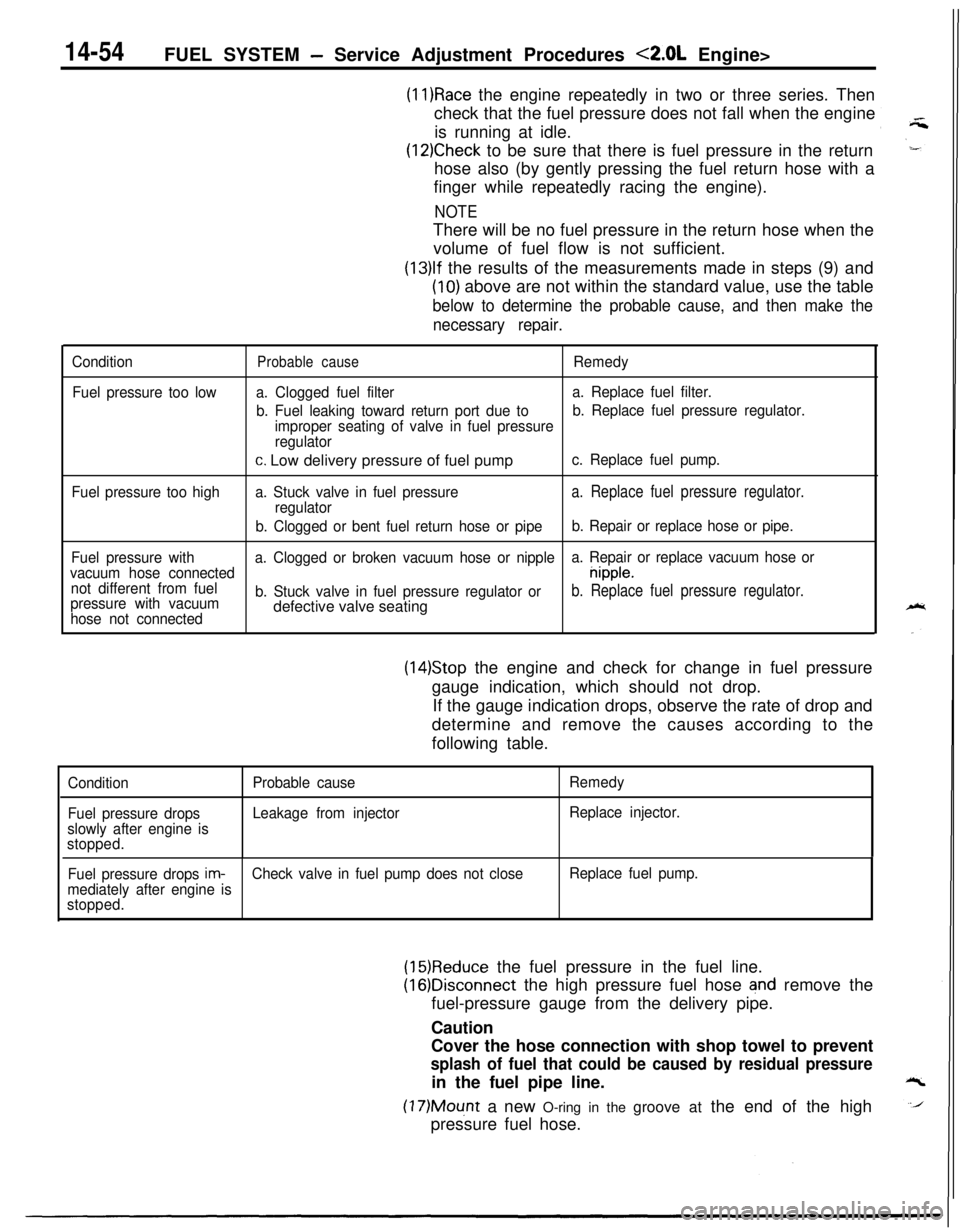
(13)lf the results of the measurements made in steps (9) and
(10) above are not within the standard value, use the table
below to determine the probable cause, and then make the
necessary repair.
Condition
Fuel pressure too lowProbable causeRemedy
a. Clogged fuel filtera. Replace fuel filter.
b. Fuel leaking toward return port due tob. Replace fuel pressure regulator.
improper seating of valve in fuel pressure
regulator
c. Low delivery pressure of fuel pumpc. Replace fuel pump.
Fuel pressure too higha. Stuck valve in fuel pressure
a. Replace fuel pressure regulator.regulator
b. Clogged or bent fuel return hose or pipeb. Repair or replace hose or pipe.
Fuel pressure witha. Clogged or broken vacuum hose or nipplea. Repair or replace vacuum hose or
vacuum hose connected
nipple.
not different from fuel
pressure with vacuumb. Stuck valve in fuel pressure regulator or
b. Replace fuel pressure regulator.
hose not connecteddefective valve seating
(14)Stop the engine and check for change in fuel pressure
gauge indication, which should not drop.
If the gauge indication drops, observe the rate of drop and
determine and remove the causes according to the
following table.
Condition
Fuel pressure drops
slowly after engine is
stopped.Probable cause
Leakage from injectorRemedy
Replace injector.
Fuel pressure drops
im-Check valve in fuel pump does not closeReplace fuel pump.
mediately after engine is
stopped.
(15)Reduce the fuel pressure in the fuel line.
(16)Disconnect the high pressure fuel hose and remove the
fuel-pressure gauge from the delivery pipe.
Caution
Cover the hose connection with shop towel to prevent
splash of fuel that could be caused by residual pressurein the fuel pipe line.
(17)Mount a new O-ring in the groove at the end of the high
pressure fuel hose.
Page 561 of 1216
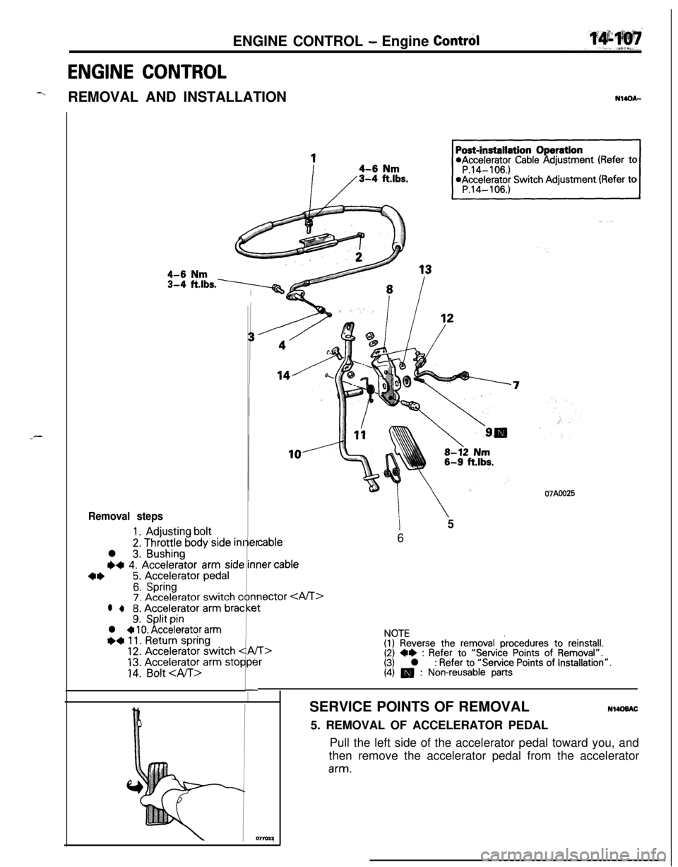
ENGINE CONTROL - Engine Contrd
ENGINE CONTROL
YREMOVAL AND INSTALLATIONN14QA-
_-
Es.-
1*Accelerator Cable Adjustment (Refer to
*Accelerator Switch Adjustment (Refer to
Removal steps
1.Adjusting bolt
2. Throttle body side inrl
3.Bushing
+4 4. Accelerator arm side
4*5. Accelerator pedal
6.Spring7. Accelerator switch CI
l +8. Accelerator arm brat9.Split pinl + 10. Accelerator armI)+ 11. Return spring12. Accelerator switch <
13. Accelerator arm stop
14.Bolt
i -7I
I
Q7
er
inr
nr
e
1A/
w07AOO25
cable
\56
ler cable
nectar
t
T>r
NOTE(I) Reverse the removal procedures to reinstall.(2) ++ : Refer to “Service Points of Removal”.(3) l : Refer to “Service Points of Installation”.(4) m : Non-reusable partsSERVICE POINTS OF REMOVAL
NlUlBAC5. REMOVAL OF ACCELERATOR PEDAL
Pull the left side of the accelerator pedal toward you, and
then remove the accelerator pedal from the acceleratorarm.
Page 634 of 1216
17-24REAR SUSPENSION
1
II
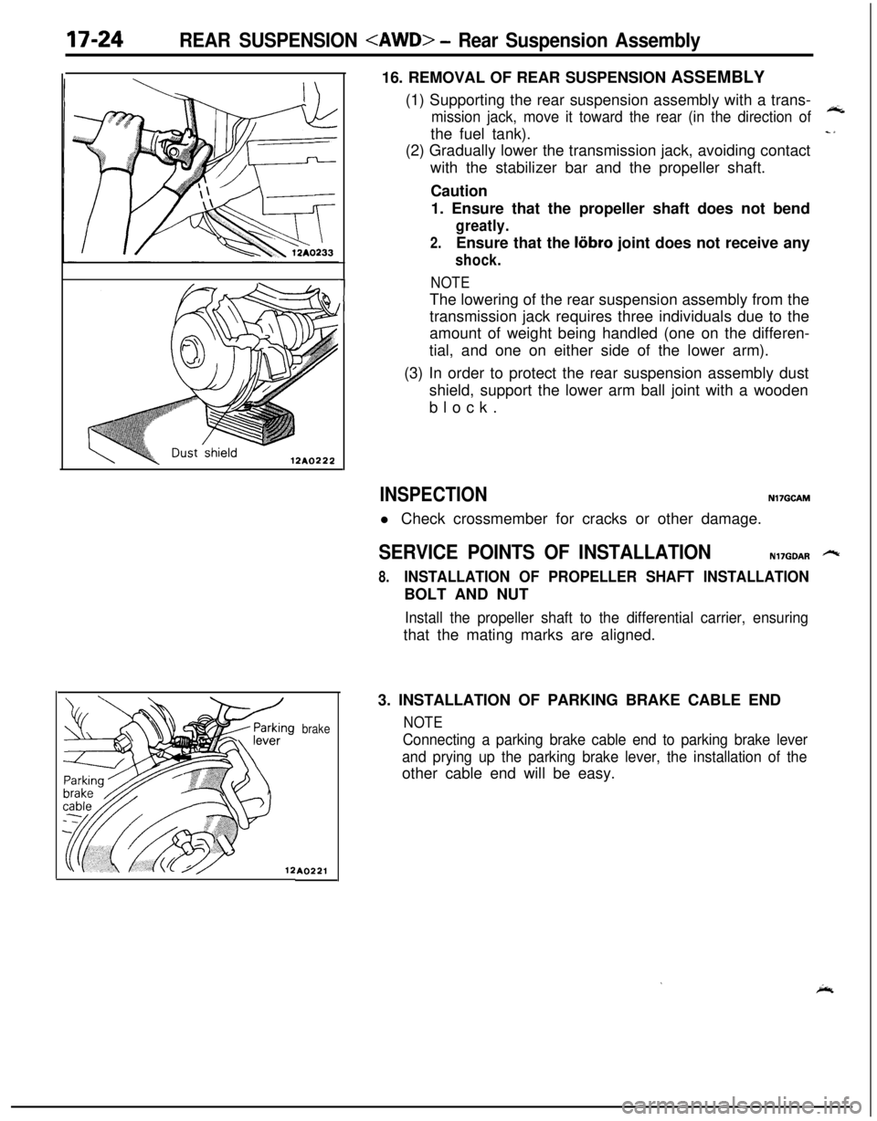
brakeA022116. REMOVAL OF REAR SUSPENSION ASSEMBLY
(1) Supporting the rear suspension assembly with a trans-
mission jack, move it toward the rear (in the direction of
wtthe fuel tank).
c1(2) Gradually lower the transmission jack, avoiding contact
with the stabilizer bar and the propeller shaft.
Caution
1. Ensure that the propeller shaft does not bend
greatly.
2.Ensure that the liibro joint does not receive any
shock.
NOTEThe lowering of the rear suspension assembly from the
transmission jack requires three individuals due to the
amount of weight being handled (one on the differen-
tial, and one on either side of the lower arm).
(3) In order to protect the rear suspension assembly dust
shield, support the lower arm ball joint with a wooden
block.
INSPECTIONNl7GCAMl Check crossmember for cracks or other damage.
SERVICE POINTS OF INSTALLATIONN17GOAR -
8.INSTALLATION OF PROPELLER SHAFT INSTALLATIONBOLT AND NUT
Install the propeller shaft to the differential carrier, ensuringthat the mating marks are aligned.
3. INSTALLATION OF PARKING BRAKE CABLE END
NOTE
Connecting a parking brake cable end to parking brake lever
and prying up the parking brake lever, the installation of theother cable end will be easy.
’ice,
Page 656 of 1216
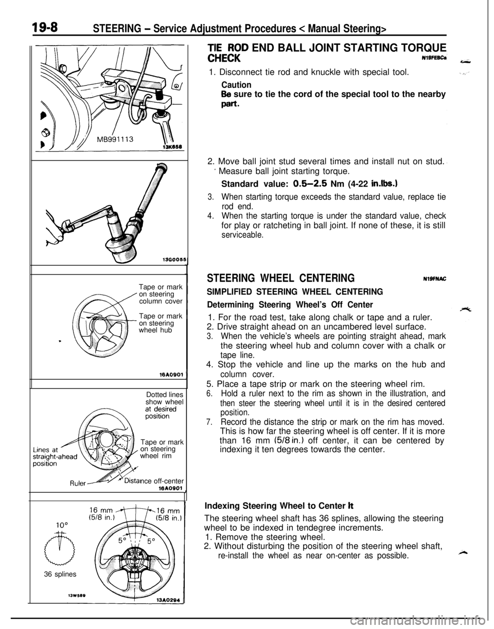
19-8STEERING - Service Adjustment Procedures < Manual Steering>
136005!Tape or mark
on steering
column cover
Tape or mark
on steering
wheel hub16A0901
Dotted lines
show wheel
Tape or mark
on steering
wheel rim
nce off-center
16AOOOl
IO036 splines
;EEE;D END BALL JOINT STARTING TORQUE
Nl9FEBCa1. Disconnect tie rod and knuckle with special tool.
Caution
Be sure to tie the cord of the special tool to the nearby
part-2. Move ball joint stud several times and install nut on stud.
’ Measure ball joint starting torque.
Standard value:
0.5-2.5 Nm (4-22 in.lbs.1
3.When starting torque exceeds the standard value, replace tie
rod end.
4.When the starting torque is under the standard value, checkfor play or ratcheting in ball joint. If none of these, it is still
serviceable.
STEERING WHEEL CENTERINGNlSFNAC
SIMPLIFIED STEERING WHEEL CENTERING
Determining Steering Wheel’s Off Center1. For the road test, take along chalk or tape and a ruler.
2. Drive straight ahead on an uncambered level surface.
3.When the vehicle’s wheels are pointing straight ahead, markthe steering wheel hub and column cover with a chalk or
tape line.4. Stop the vehicle and line up the marks on the hub and
column cover.5. Place a tape strip or mark on the steering wheel rim.
6.Hold a ruler next to the rim as shown in the illustration, and
then steer the steering wheel until it is in the desired centered
position.
7.Record the distance the strip or mark on the rim has moved.This is how far the steering wheel is off center. If it is more
than 16 mm
(518 in.) off center, it can be centered by
indexing it ten degrees towards the center.
,Indexing Steering Wheel to Center
ltThe steering wheel shaft has 36 splines, allowing the steering
wheel to be indexed in tendegree increments.
1. Remove the steering wheel.
2. Without disturbing the position of the steering wheel shaft,
re-install the wheel as near on-center as possible.
Page 657 of 1216
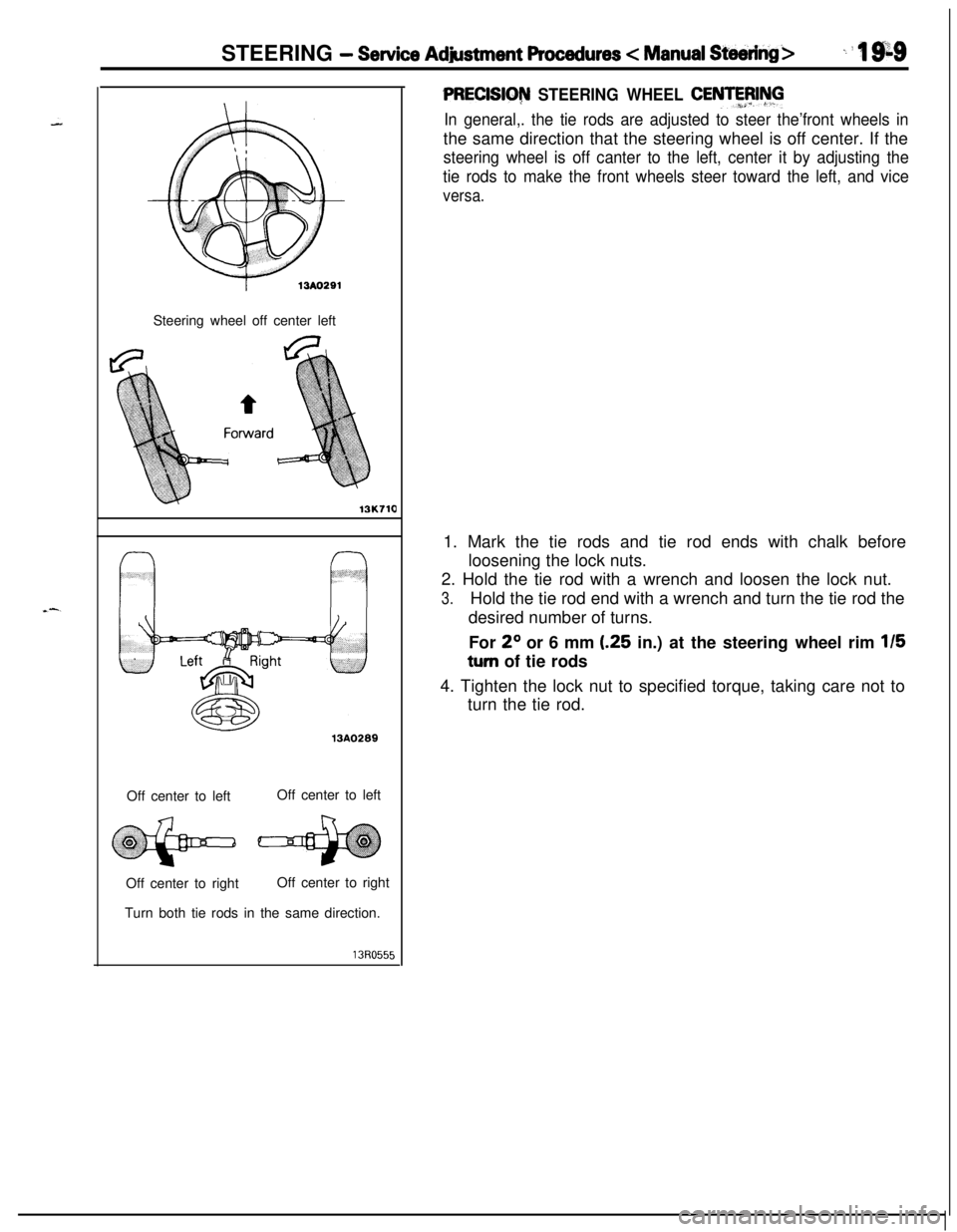
STEERING - Service Adjustment Procedures < Manual Steering>_ i ‘I 9;sSteering wheel off center left
13K71013A0289
Off center to leftOff center to left
Off center to rightOff center to right
Turn both tie rods in the same direction.
PRECISIG~ STEERING WHEEL CENTFFJIhll
In general,. the tie rods are adjusted to steer the’front wheels inthe same direction that the steering wheel is off center. If the
steering wheel is off canter to the left, center it by adjusting the
tie rods to make the front wheels steer toward the left, and vice
versa.1. Mark the tie rods and tie rod ends with chalk before
loosening the lock nuts.
2. Hold the tie rod with a wrench and loosen the lock nut.
3.Hold the tie rod end with a wrench and turn the tie rod the
desired number of turns.
For
2O or 6 mm (.25 in.) at the steering wheel rim 115
turn of tie rods
4. Tighten the lock nut to specified torque, taking care not to
turn the tie rod.
Page 658 of 1216
19-10STEERING - Service Adjustment Procedures c Power Steering>
r13A029213A0293
r
1
i
SERVICE ADJUSTMENT PROCEDURES
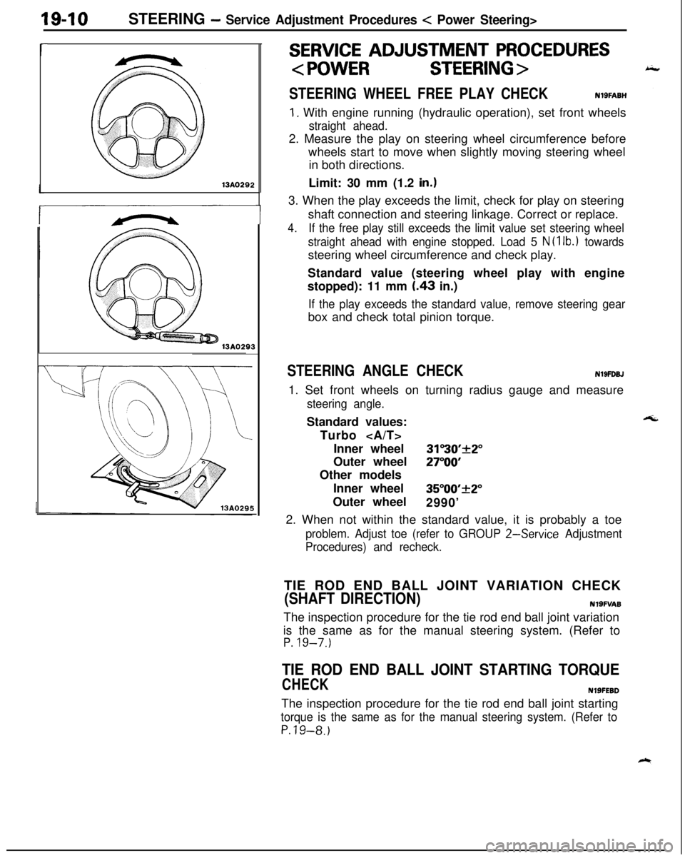
STEERING WHEEL FREE PLAY CHECKNlSFABH
1. With engine running (hydraulic operation), set front wheels
straight ahead.2. Measure the play on steering wheel circumference before
wheels start to move when slightly moving steering wheel
in both directions.
Limit: 30 mm (1.2
in.13. When the play exceeds the limit, check for play on steering
shaft connection and steering linkage. Correct or replace.
4.If the free play still exceeds the limit value set steering wheel
straight ahead with engine stopped. Load 5
N (1 lb.1 towardssteering wheel circumference and check play.
Standard value (steering wheel play with engine
stopped): 11 mm
I.43 in.)
If the play exceeds the standard value, remove steering gearbox and check total pinion torque.
STEERING ANGLE CHECKN19FDBJ1. Set front wheels on turning radius gauge and measure
steering angle.Standard values:
Turbo
Inner wheel
31”30’+2”Outer wheel
27”OOOther models
Inner wheel
35”00’_+2”Outer wheel
2990’
2. When not within the standard value, it is probably a toe
problem. Adjust toe (refer to GROUP 2-Service Adjustment
Procedures) and recheck.TIE ROD END BALL JOINT VARIATION CHECK
(SHAFT DIRECTION)N19FVA8The inspection procedure for the tie rod end ball joint variation
is the same as for the manual steering system. (Refer to
P. 19-7.)
TIE ROD END BALL JOINT STARTING TORQUE
CHECKNlSFEBDThe inspection procedure for the tie rod end ball joint starting
torque is the same as for the manual steering system. (Refer to
P.19-8.)
Page 666 of 1216
19-18STEERING - Steering Wheel and Shaft
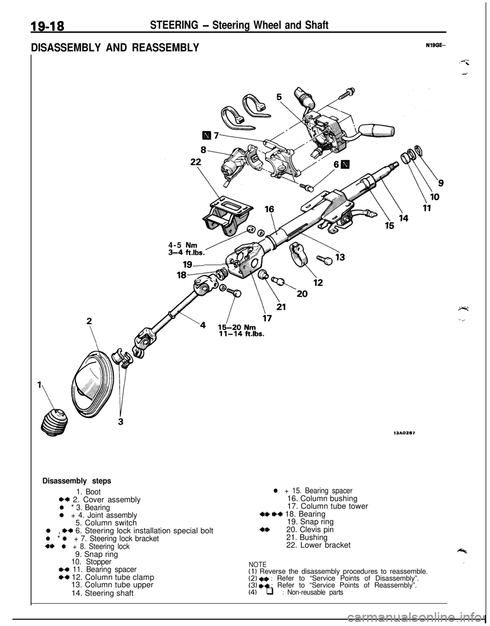
DISASSEMBLY AND REASSEMBLYNlBGE-
4-5
Nm3-4;lbs. -6
18-z.
11-14 ft.lbs.
13AO287
Disassembly steps
1. Boot*+ 2. Cover assemblyl * 3. Bearingl + 4. Joint assembly5. Column switch
l ,
.+ 6. Steering lock installation special boltl * l + 7. Steering lock bracket+I) l + 8. Steering lock9. Snap ring
10. Stopper~~ 11. Bearing spacerW 12. Column tube clamp
13. Column tube upper
14. Steering shaft
l + 15. Bearing spacer16. Column bushing
17. Column tube tower
4, ,+ 18. Bearing
19. Snap ring
4,20. Clevis pin
21. Bushing
22. Lower bracket
NOTE(I 1 Reverse the disassembly procedures to reassemble.(2) +I) : Refer to “Service Points of Disassembly”.(3) I)+ : Refer to “Service Points of Reassembly”.(4) q : Non-reusable parts
‘I