tow MITSUBISHI ECLIPSE 1991 Owner's Guide
[x] Cancel search | Manufacturer: MITSUBISHI, Model Year: 1991, Model line: ECLIPSE, Model: MITSUBISHI ECLIPSE 1991Pages: 1216, PDF Size: 67.42 MB
Page 674 of 1216
19-26STEERING - Manual Steering Gear Box
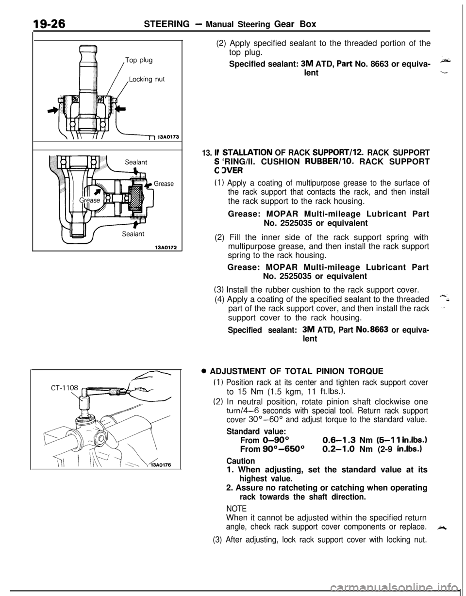
Grease
13AO172(2) Apply specified sealant to the threaded portion of the
top plug.
Specified sealant:
3M ATD, Part No. 8663 or equiva-klent
13. lr
:
ISTALLATION OF RACK SUPPORT/l2. RACK SUPPORT‘RING/II. CUSHION RUBBER/IO. RACK SUPPORT
3VER
(I) Apply a coating of multipurpose grease to the surface of
the rack support that contacts the rack, and then installthe rack support to the rack housing.
Grease: MOPAR Multi-mileage Lubricant Part
No. 2525035 or equivalent
(2) Fill the inner side of the rack support spring with
multipurpose grease, and then install the rack support
spring to the rack housing.
Grease: MOPAR Multi-mileage Lubricant Part
No. 2525035 or equivalent
(3) Install the rubber cushion to the rack support cover.
(4) Apply a coating of the specified sealant to the threaded
-Lpart of the rack support cover, and then install the rack
.‘.support cover to the rack housing.
Specified sealant:3M ATD, Part No.8663 or equiva-lent0 ADJUSTMENT OF TOTAL PINION TORQUE
(1
(2
) Position rack at its center and tighten rack support coverto 15 Nm (1.5 kgm, 11
ftlbs.).
:) In neutral position, rotate pinion shaft clockwise one
turn/4-6 seconds with special tool. Return rack support
cover
30”-60” and adjust torque to the standard value.
Standard value:
From
0-90°From
90°-650°
Caution
0.6-I .3 Nm (5-l 1 inIbs.
0.2-1.0 Nm (2-9 in.lbs.1
I. When adjusting, set the standard value at its
highest value.2. Assure no ratcheting or catching when operating
rack towards the shaft direction.
NOTEWhen it cannot be adjusted within the specified return
angle, check rack support cover components or replace.A
(3) After adjusting, lock rack support cover with locking nut.
Page 685 of 1216
STEERING - Power Steering Gear Box
13A017EI
\Silicon grease
Lip
Sealant131564-r-MB990776-A
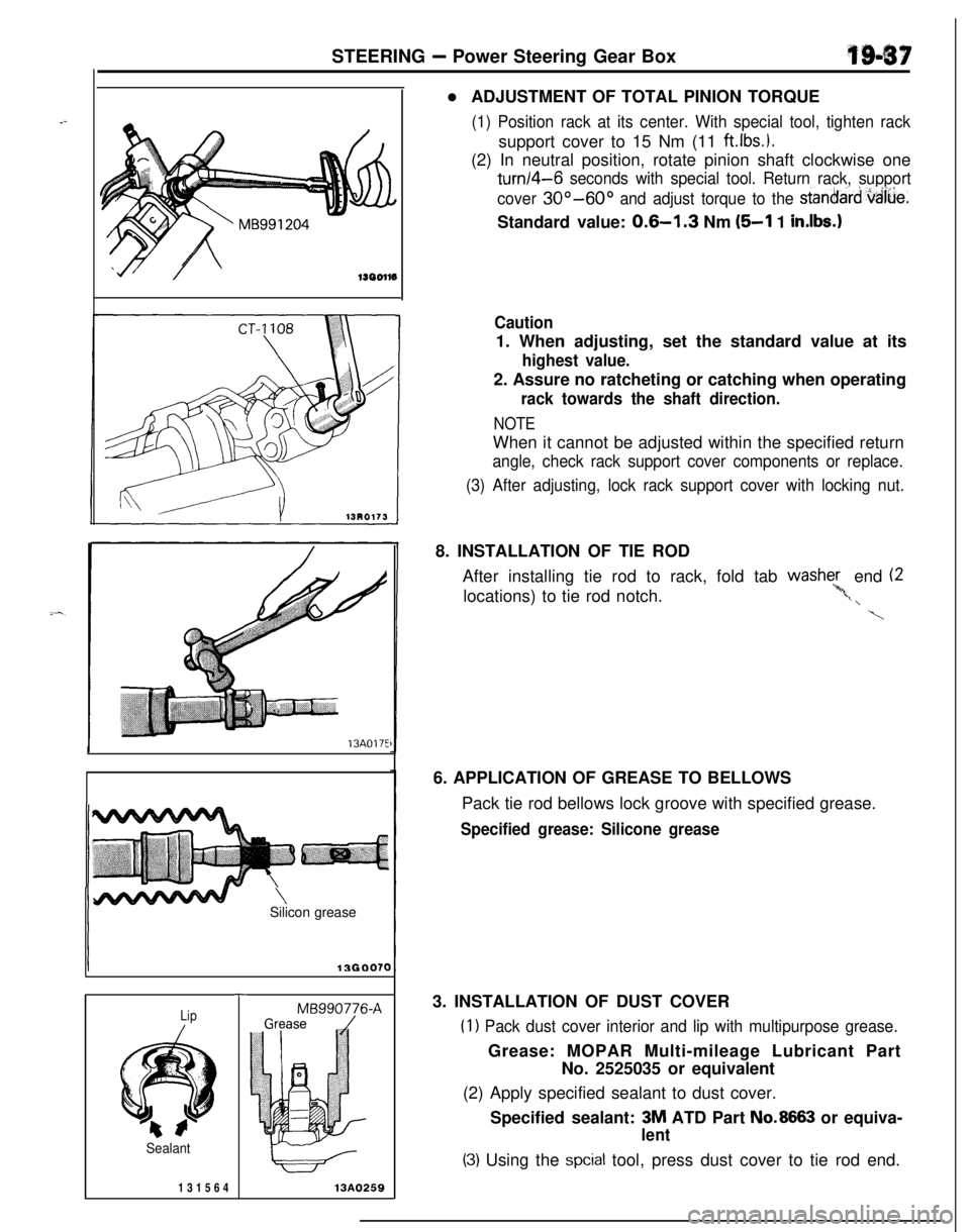
13A0259l ADJUSTMENT OF TOTAL PINION TORQUE
(1) Position rack at its center. With special tool, tighten racksupport cover to 15 Nm (11
ftlbs.).(2) In neutral position, rotate pinion shaft clockwise one
turn/4-6 seconds with special tool. Return rack, support
cover
30°-60° and adjust torque to the stanoard,vaiue.Standard value:
0.6-l .3 Nm (5-l 1 in.lbs.1
Caution1. When adjusting, set the standard value at its
highest value.2. Assure no ratcheting or catching when operating
rack towards the shaft direction.
NOTEWhen it cannot be adjusted within the specified return
angle, check rack support cover components or replace.
(3) After adjusting, lock rack support cover with locking nut.8. INSTALLATION OF TIE ROD
After installing tie rod to rack, fold tab washe;, end (2
locations) to tie rod notch.
‘*,t, \
\6. APPLICATION OF GREASE TO BELLOWS
Pack tie rod bellows lock groove with specified grease.
Specified grease: Silicone grease3. INSTALLATION OF DUST COVER
(1) Pack dust cover interior and lip with multipurpose grease.Grease: MOPAR Multi-mileage Lubricant Part
No. 2525035 or equivalent
(2) Apply specified sealant to dust cover.
Specified sealant: 3M ATD Part
No.8663 or equiva-
lent
(3) Using the spcial tool, press dust cover to tie rod end.
Page 740 of 1216
21-46MANUAL TRANSAXLE
201051
TFMO119
Damage, breakage
/
Synchronizer ringGLarTFMOlli
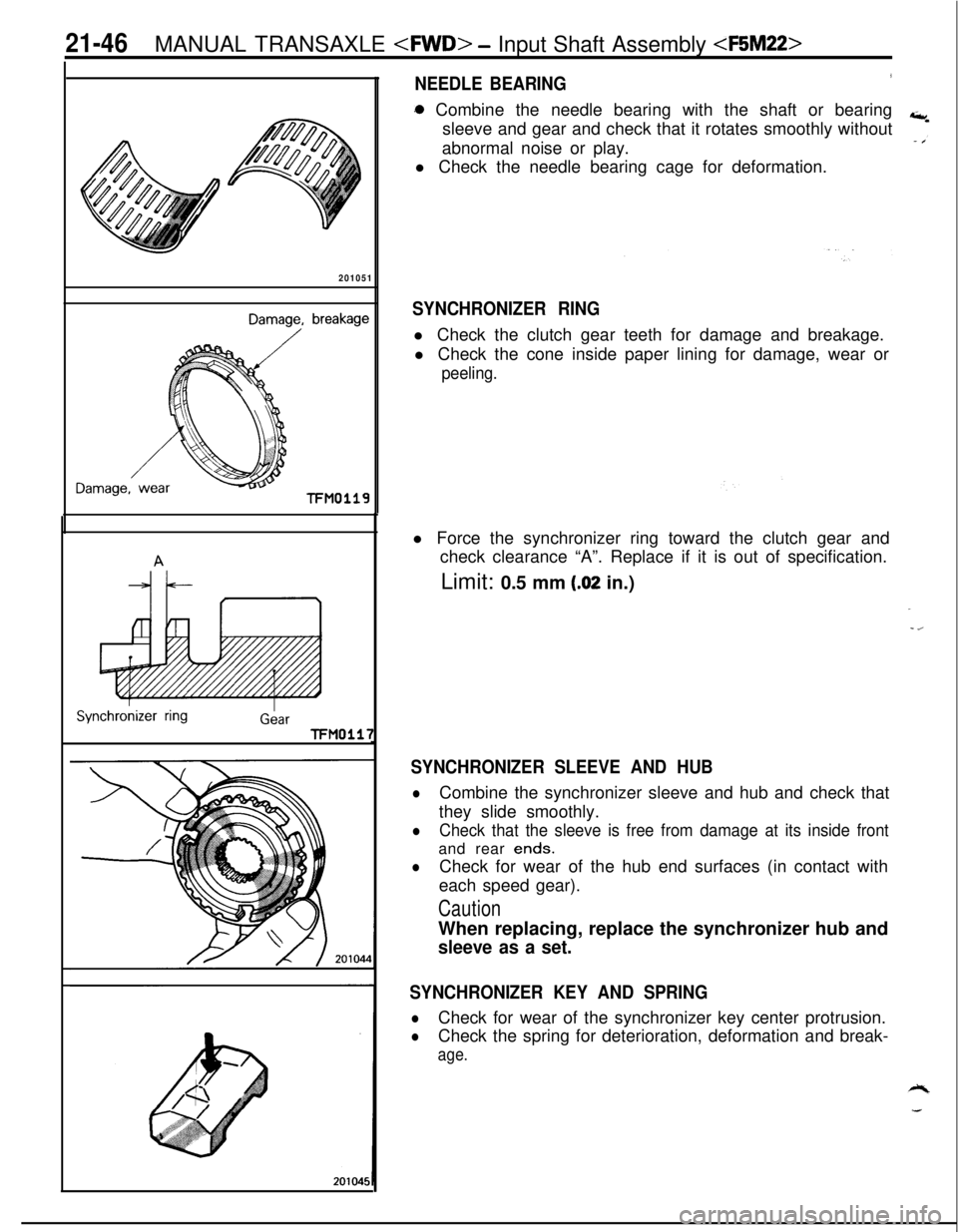
NEEDLE BEARING3a Combine the needle bearing with the shaft or bearing
sleeve and gear and check that it rotates smoothly without
abnormal noise or play.
l Check the needle bearing cage for deformation.
SYNCHRONIZER RINGl Check the clutch gear teeth for damage and breakage.
l Check the cone inside paper lining for damage, wear or
peeling.l Force the synchronizer ring toward the clutch gear and
check clearance “A”. Replace if it is out of specification.
Limit: 0.5 mm
(.02 in.)
SYNCHRONIZER SLEEVE AND HUB
lCombine the synchronizer sleeve and hub and check that
they slide smoothly.
lCheck that the sleeve is free from damage at its inside frontand rear
ends.
lCheck for wear of the hub end surfaces (in contact with
each speed gear).
CautionWhen replacing, replace the synchronizer hub and
sleeve as a set.
SYNCHRONIZER KEY AND SPRING
lCheck for wear of the synchronizer key center protrusion.
lCheck the spring for deterioration, deformation and break-
age.
Page 742 of 1216
21-48 MANUAL TRANSAXLE
4th speedgear sideTFM004:
2060006
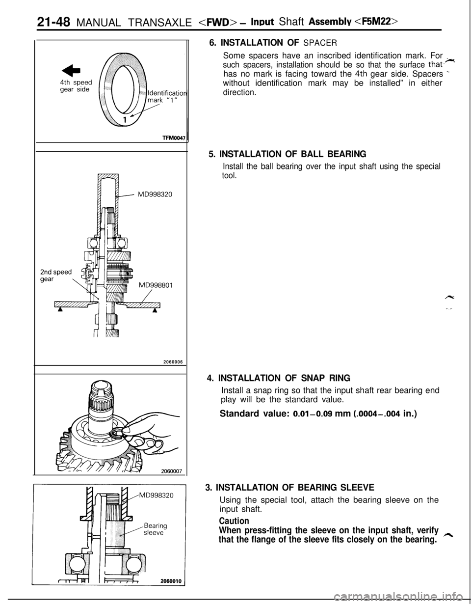
6. INSTALLATION OF SPACERSome spacers have an inscribed identification mark. For
_
such spacers, installation should be so that the surface that.-has no mark is facing toward the
4th gear side. Spacers -without identification mark may be installed” in either
direction.
5. INSTALLATION OF BALL BEARING
Install the ball bearing over the input shaft using the special
tool.
4. INSTALLATION OF SNAP RINGInstall a snap ring so that the input shaft rear bearing end
play will be the standard value.
Standard value: 0.01-0.09 mm
(.0004-.004 in.)
3. INSTALLATION OF BEARING SLEEVEUsing the special tool, attach the bearing sleeve on the
input shaft.
Caution
When press-fitting the sleeve on the input shaft, verify
that the flange of the sleeve fits closely on the bearing.
h
Page 746 of 1216

21-52 MANUAL TRANSAXLE
r
201051
Damage, breakage
Damage,TFMO119
ISynchronver ringGearTFM0117
2010441
NEEDLE BEARINGl Combine the needle bearing with the shaft or bearing
+,sleeve and gear and check that it rotates smoothly without
abnormal noise or play.
l Check the needle bearing cage for deformation.
SYNCHRONIZER RINGl Check the clutch gear teeth for damage and breakage.
l Check the cone inside paper lining for damage, wear or
peeling.l Force the synchronizer ring toward the clutch gear and
check clearance “A”. Replace if it is out of specification.
Limit: 0.5 mm
(.02 in.)
-z
SYNCHRONIZER SLEEVE AND HUB
lCombine the synchronizer sleeve and hub and check that
they slide smoothly.
lCheck that the sleeve is free from damage at its inside frontand rear ends.
lCheck for wear of the hub end surfaces (in contact with
each speed gear).
CautionWhen replacing, replace the synchronizer hub and
sleeve as a set.
SYNCHRONIZER KEY AND SPRING
lCheck for wear of the synchronizer key center protrusion.
lCheck the spring for deterioration, deformation and break-
age.
Page 752 of 1216
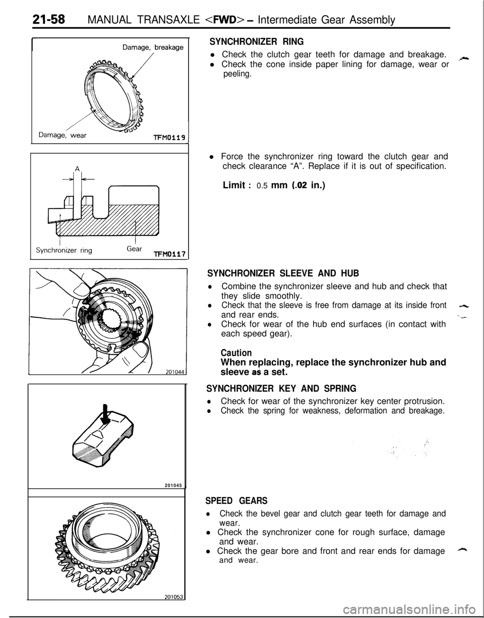
21-58MANUAL TRANSAXLE
rDamage, breakage
Damage, wearl-FM0119
ISynchronizer ring
IGearTFM0117
SYNCHRONIZER RINGl Check the clutch gear teeth for damage and breakage.
l Check the cone inside paper lining for damage, wear or
~
peeling.
J
201045l Force the synchronizer ring toward the clutch gear and
check clearance “A”. Replace if it is out of specification.
Limit
:0.5 mm (.02 in.)
SYNCHRONIZER SLEEVE AND HUB
lCombine the synchronizer sleeve and hub and check that
they slide smoothly.
lCheck that the sleeve is free from damage at its inside front-4rand rear ends.
-.--
lCheck for wear of the hub end surfaces (in contact with
each speed gear).
CautionWhen replacing, replace the synchronizer hub and
sleeve
aS a set.
SYNCHRONIZER KEY AND SPRING
lCheck for wear of the synchronizer key center protrusion.
lCheck the spring for weakness, deformation and breakage.
SPEED GEARS
lCheck the bevel gear and clutch gear teeth for damage and
wear.l Check the synchronizer cone for rough surface, damage
and wear.
l Check the gear bore and front and rear ends for damage
kand wear.
Page 806 of 1216
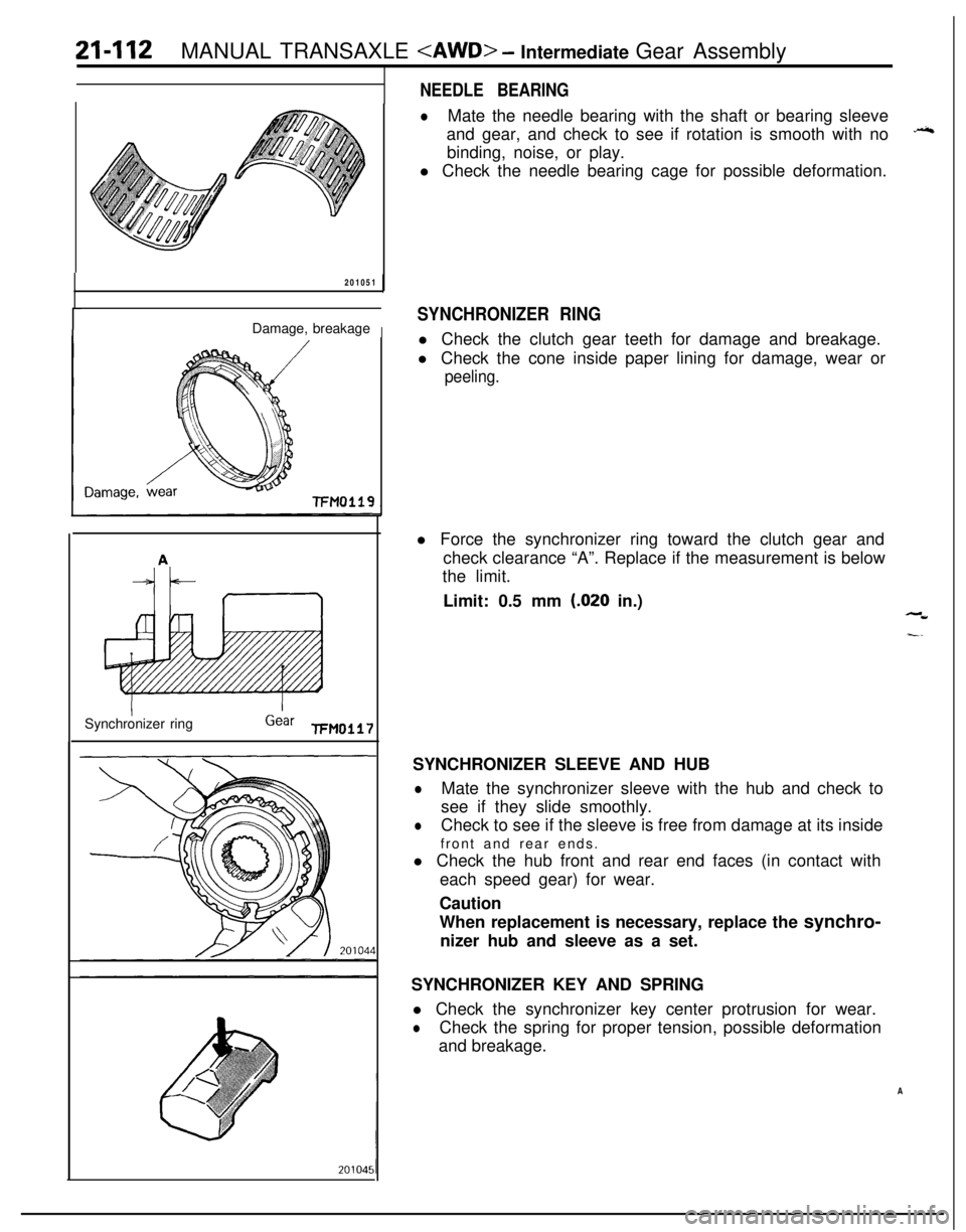
21-112MANUAL TRANSAXLE
201051
Damage, breakage
I
-FM0119Synchronizer ring
Gear FM0117
NEEDLE BEARING
lMate the needle bearing with the shaft or bearing sleeve
and gear, and check to see if rotation is smooth with no
++binding, noise, or play.
l Check the needle bearing cage for possible deformation.
SYNCHRONIZER RINGl Check the clutch gear teeth for damage and breakage.
l Check the cone inside paper lining for damage, wear or
peeling.l Force the synchronizer ring toward the clutch gear and
check clearance “A”. Replace if the measurement is below
the limit.
Limit: 0.5 mm
(.020 in.),-W
I-.SYNCHRONIZER SLEEVE AND HUB
lMate the synchronizer sleeve with the hub and check to
see if they slide smoothly.
lCheck to see if the sleeve is free from damage at its inside
front and rear ends.
l Check the hub front and rear end faces (in contact with
each speed gear) for wear.
Caution
When replacement is necessary, replace the synchro-
nizer hub and sleeve as a set.
SYNCHRONIZER KEY AND SPRING
l Check the synchronizer key center protrusion for wear.
lCheck the spring for proper tension, possible deformation
and breakage.
A
Page 811 of 1216
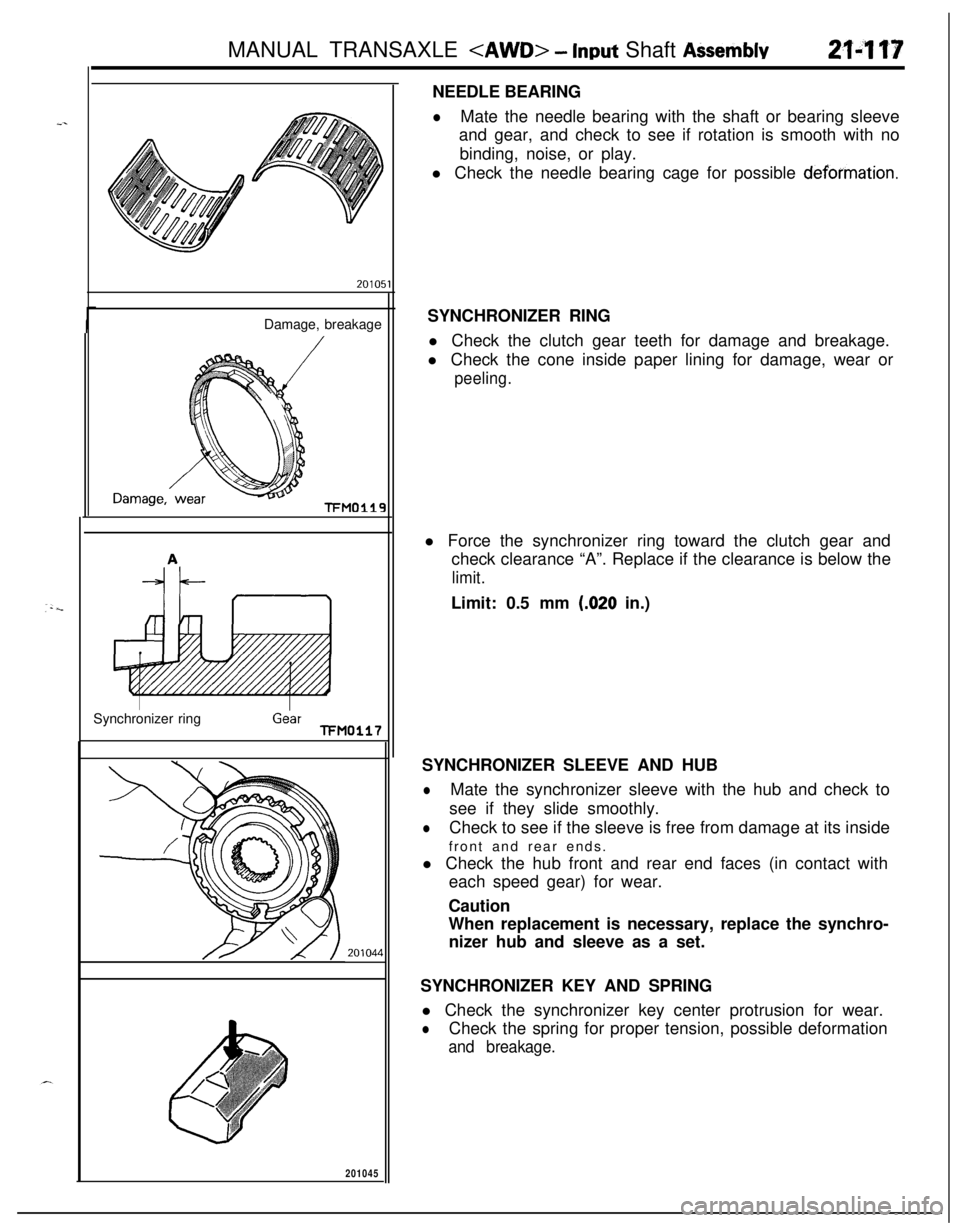
MANUAL TRANSAXLE
_.Damage, breakage
TFMO119Synchronizer ring
GearTFM0117
20104~
201045
1NEEDLE BEARING
lMate the needle bearing with the shaft or bearing sleeve
and gear, and check to see if rotation is smooth with no
binding, noise, or play.
l Check the needle bearing cage for possible
deformation.SYNCHRONIZER RING
l Check the clutch gear teeth for damage and breakage.
l Check the cone inside paper lining for damage, wear or
peeling.l Force the synchronizer ring toward the clutch gear and
check clearance “A”. Replace if the clearance is below the
limit.Limit: 0.5 mm
(.020 in.)
SYNCHRONIZER SLEEVE AND HUB
lMate the synchronizer sleeve with the hub and check to
see if they slide smoothly.
lCheck to see if the sleeve is free from damage at its inside
front and rear ends.
l Check the hub front and rear end faces (in contact with
each speed gear) for wear.
Caution
When replacement is necessary, replace the synchro-
nizer hub and sleeve as a set.
SYNCHRONIZER KEY AND SPRING
l Check the synchronizer key center protrusion for wear.
lCheck the spring for proper tension, possible deformation
and breakage.
Page 831 of 1216
AUTOMATIC TRANSAXLE - General Information21437
AUTOMATIC TRANSAXLE
_,sGENERAL INFORMATION
NZlBABTaCautionary points during disassembly and
assembly of the transaxle
Because the automatic transaxle is composed ofcomponent parts of an especially high degree of
precision, these parts should be very carefully
handled during disassembly and assembly so asnot to scar or scratch them.
A rubber mat should be placed on the work-
bench, and it should always be kept clean.
During disassembly, cloth gloves or shop towelsshould not be used.
If such items must be used, use articles made ofnylon, or use paper towels.
All
disassemblyed parts must be thoroughly
cleaned.Metal parts may be cleaned with ordinary
detergents, but must be thoroughly air dried.
Clean the clutch disc, resin thrust plate and
rubber parts by using ATF (automatic transmis-
sion fluid), being very careful that dust, dirt, etc.
do not adhere.
Do not reuse gaskets, oil seals and rubber parts.Replace them with new ones at every reassem-
bly. O-ring of oil level gauge need not be
replaced.Do not use grease other than petrolatum jelly.
Apply ATF to friction element, rotating parts, andsliding parts before installation.
New clutch disc should be immersed in ATF for
more than two hours before installation.
Do not apply sealer or adhesive to gaskets.
When bushing must be replaced, replace
assembly which includes it.
If the transaxle main unit is damaged, also
disassembly and clean the cooler system.
In order to prevent a sudden start as a result of
accidental misoperation of the select lever, this
model is provided with the automatic-transaxle
safety-lock system.
Page 921 of 1216
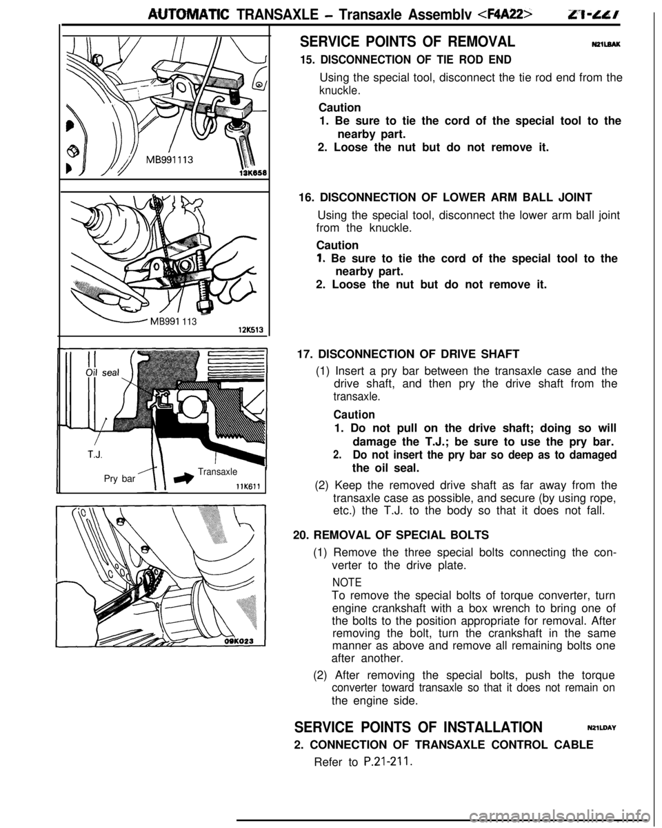
AUTOMATIC TRANSAXLE - Transaxle Assemblv
-MB991 11312K513Pry bar
*Transaxle
llK611
SERVICE POINTS OF REMOVALN2llEAK
15. DISCONNECTION OF TIE ROD ENDUsing the special tool, disconnect the tie rod end from the
knuckle.Caution
1. Be sure to tie the cord of the special tool to the
nearby part.
2. Loose the nut but do not remove it.
16. DISCONNECTION OF LOWER ARM BALL JOINT
Using the special tool, disconnect the lower arm ball joint
from the knuckle.
Caution
1. Be sure to tie the cord of the special tool to the
nearby part.
2. Loose the nut but do not remove it.
17. DISCONNECTION OF DRIVE SHAFT
(1) Insert a pry bar between the transaxle case and the
drive shaft, and then pry the drive shaft from the
transaxle.
Caution1. Do not pull on the drive shaft; doing so will
damage the T.J.; be sure to use the pry bar.
2.Do not insert the pry bar so deep as to damagedthe oil seal.
(2) Keep the removed drive shaft as far away from the
transaxle case as possible, and secure (by using rope,
etc.) the T.J. to the body so that it does not fall.
20. REMOVAL OF SPECIAL BOLTS
(1) Remove the three special bolts connecting the con-
verter to the drive plate.
NOTETo remove the special bolts of torque converter, turn
engine crankshaft with a box wrench to bring one of
the bolts to the position appropriate for removal. After
removing the bolt, turn the crankshaft in the same
manner as above and remove all remaining bolts one
after another.
(2) After removing the special bolts, push the torque
converter toward transaxle so that it does not remain onthe engine side.
SERVICE POINTS OF INSTALLATIONN2lWAY
2. CONNECTION OF TRANSAXLE CONTROL CABLE
Refer to
P.21-211.