tow MITSUBISHI ECLIPSE 1991 User Guide
[x] Cancel search | Manufacturer: MITSUBISHI, Model Year: 1991, Model line: ECLIPSE, Model: MITSUBISHI ECLIPSE 1991Pages: 1216, PDF Size: 67.42 MB
Page 308 of 1216
9-24ENGINE - Service Adjustment Procedures
ENGINE 4.8L Engine>
SERVICE ADJUSTMENT PROCEDURES -
CHECKING COMPRESSION PRESSURENOSFFAI
(1) Before checking compression, ensure that engine oil, the
starter motor, and battery are all in good condition.
(2) Start the engine and wait until engine coolant temperature
has risen to
85-95°C (185-205°F).
(3) Stop the engine and pull the spark plug cables.
(4) Remove the spark plugs.
(5) Crank the engine to remove any foreign objects in the
cylinders.Caution
Cover the spark plug holes with shop towel, etc., in
order to keep expelled foreign objects from flying out,
and keep away from the holes. When measuring
compression with water, oil, or fuel having entered the
cylinder through a crack, etc., these will come flying
out of the spark plug hole hot and fast, so be sure to
take the proper precautions.
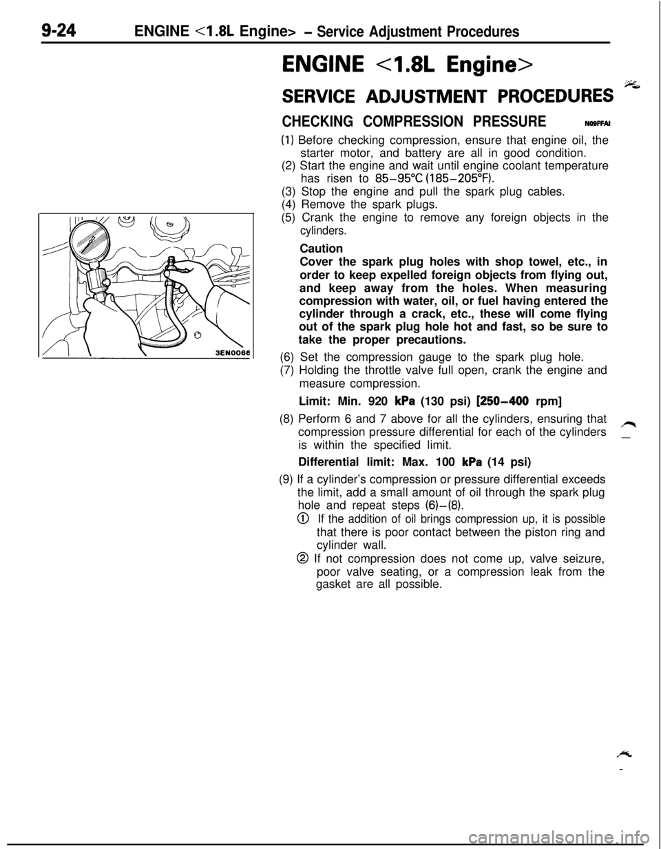
(6) Set the compression gauge to the spark plug hole.
(7) Holding the throttle valve full open, crank the engine and
measure compression.
Limit: Min. 920
kPa (130 psi) [250-400 rpm]
(8) Perform 6 and 7 above for all the cylinders, ensuring that
compression pressure differential for each of the cylinders
/Iis within the specified limit.
__Differential limit: Max. 100
kPa (14 psi)
(9) If a cylinder’s compression or pressure differential exceeds
the limit, add a small amount of oil through the spark plug
hole and repeat steps (6)-(8).
0If the addition of oil brings compression up, it is possiblethat there is poor contact between the piston ring and
cylinder wall.
@ If not compression does not come up, valve seizure,
poor valve seating, or a compression leak from the
gasket are all possible.
/y
-
Page 329 of 1216
ENGINE <1.8L Engine> - Timing Belt9-45
J
I01R0409
Crankshaftsprocket )IB”
I
CrankshafisprocketCrankshaft
6EN2721
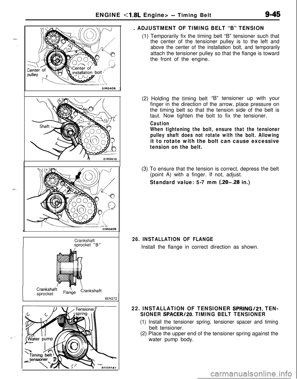
. ADJUSTMENT OF TIMING BELT “B” TENSION(1) Temporarily fix the timing belt “B” tensioner such that
the center of the tensioner pulley is to the left and
above the center of the installation bolt, and temporarilyattach the tensioner pulley so that the flange is toward
the front of the engine.
(2) Holding the timing belt“B” tensioner up with your
finger in the direction of the arrow, place pressure on
the timing belt so that the tension side of the belt is
taut. Now tighten the bolt to fix the tensioner.
Caution
When tightening the bolt, ensure that the tensioner
pulley shaft does not rotate with the bolt. Allowing
it to rotate with the bolt can cause excessive
tension on the belt.(3) To ensure that the tension is correct, depress the belt
(point A) with a finger. If not, adjust.
Standard value: 5-7 mm (.20-.28 in.)
26. INSTALLATION OF FLANGEInstall the flange in correct direction as shown.
22. INSTALLATION OF TENSIONER SPRING/21. TEN-
SIONER SPACERI20. TIMING BELT TENSIONER
(1) Install the tensioner spring, tensioner spacer and timingbelt tensioner.
(2) Place the upper end of the tensioner spring against the
water pump body.
Page 330 of 1216
9-46ENGINE <1.8L Engine> - Timing Belt
Timing mark
Q1hQS4.9
3EN005
OlA0549
c
::
OlAO550-(3) Move tensioner fully toward water pump and tempor-
arily secure tensioner.
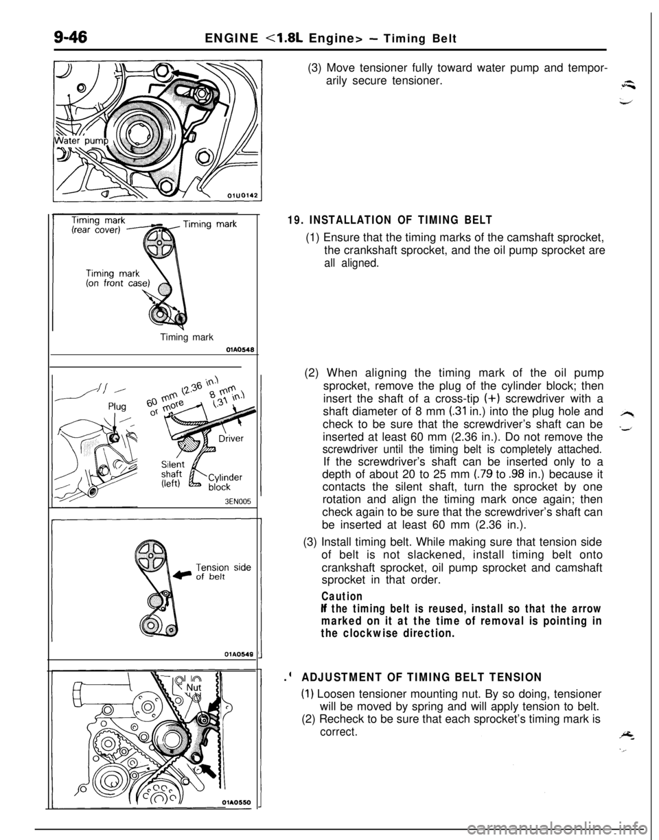
19. INSTALLATION OF TIMING BELT(1) Ensure that the timing marks of the camshaft sprocket,
the crankshaft sprocket, and the oil pump sprocket are
all aligned.(2) When aligning the timing mark of the oil pump
sprocket, remove the plug of the cylinder block; then
insert the shaft of a cross-tip (+) screwdriver with a
shaft diameter of 8 mm
(.31 in.) into the plug hole and
check to be sure that the screwdriver’s shaft can be
inserted at least 60 mm (2.36 in.). Do not remove the
screwdriver until the timing belt is completely attached.If the screwdriver’s shaft can be inserted only to a
depth of about 20 to 25 mm
(.79 to .98 in.) because it
contacts the silent shaft, turn the sprocket by one
rotation and align the timing mark once again; then
check again to be sure that the screwdriver’s shaft can
be inserted at least 60 mm (2.36 in.).
(3) Install timing belt. While making sure that tension side
of belt is not slackened, install timing belt onto
crankshaft sprocket, oil pump sprocket and camshaft
sprocket in that order.
Caution
If the timing belt is reused, install so that the arrow
marked on it at the time of removal is pointing in
the clockwise direction..
ADJUSTMENT OF TIMING BELT TENSION
(1) Loosen tensioner mounting nut. By so doing, tensioner
will be moved by spring and will apply tension to belt.
(2) Recheck to be sure that each sprocket’s timing mark is
correct.
Page 331 of 1216
ENGINE <1.8L Engine> - Timing Belt9-47
Timing mark
Nut
;olt diameter x lengthim (in.)
6x50(.23 x 1.97)
6
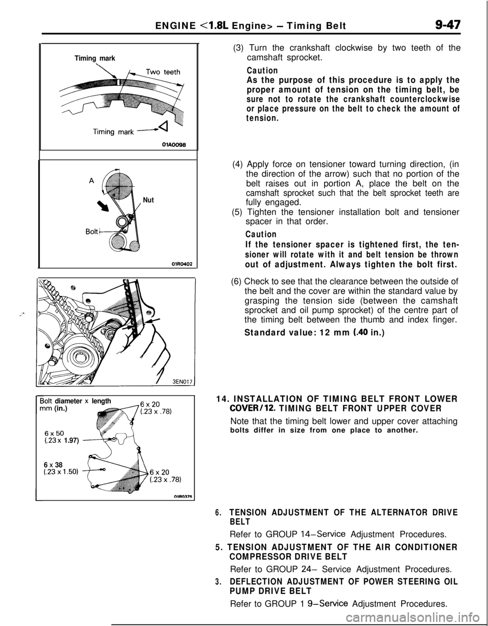
x 38(.23 x 1.50)(3) Turn the crankshaft clockwise by two teeth of the
camshaft sprocket.
Caution
As the purpose of this procedure is to apply the
proper amount of tension on the timing belt, be
sure not to rotate the crankshaft counterclockwise
or place pressure on the belt to check the amount of
tension.(4) Apply force on tensioner toward turning direction, (in
the direction of the arrow) such that no portion of the
belt raises out in portion A, place the belt on the
camshaft sprocket such that the belt sprocket teeth arefully engaged.
(5) Tighten the tensioner installation bolt and tensioner
spacer in that order.
Caution
If the tensioner spacer is tightened first, the ten-
sioner will rotate with it and belt tension be thrown
out of adjustment. Always tighten the bolt first.(6) Check to see that the clearance between the outside of
the belt and the cover are within the standard value by
grasping the tension side (between the camshaft
sprocket and oil pump sprocket) of the centre part of
the timing belt between the thumb and index finger.
Standard value: 12 mm (.40 in.)
14. INSTALLATION OF TIMING BELT FRONT LOWER
COVER/12. TIMING BELT FRONT UPPER COVERNote that the timing belt lower and upper cover attaching
bolts differ in size from one place to another.
6.TENSION ADJUSTMENT OF THE ALTERNATOR DRIVE
BELTRefer to GROUP
14-Service Adjustment Procedures.
5. TENSION ADJUSTMENT OF THE AIR CONDITIONER
COMPRESSOR DRIVE BELTRefer to GROUP
24- Service Adjustment Procedures.
3.DEFLECTION ADJUSTMENT OF POWER STEERING OIL
PUMP DRIVE BELTRefer to GROUP 1
g-Service Adjustment Procedures.
Page 341 of 1216
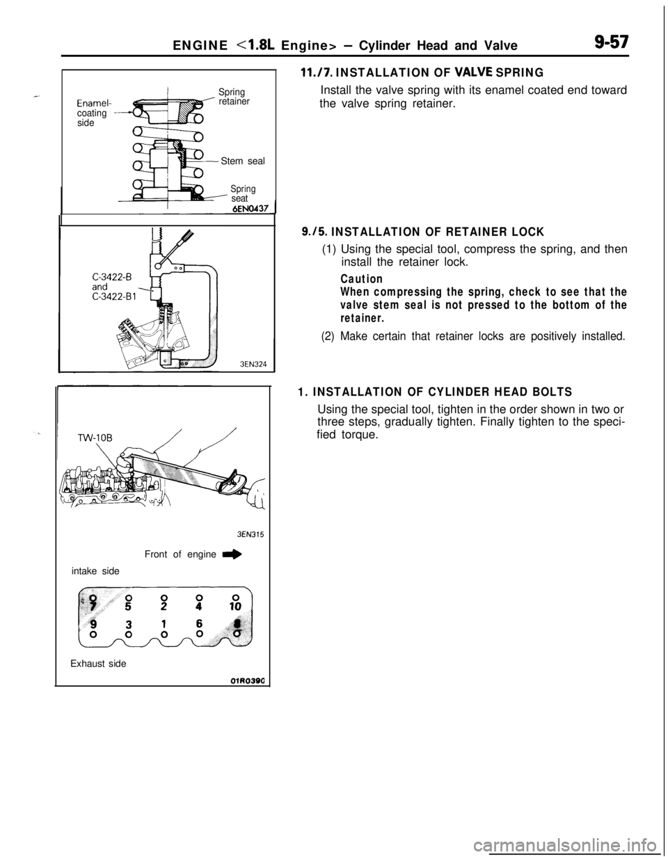
ENGINE <1.8L Engine> - Cylinder Head and Valve9-57
Enamel-
coating
sideSpring
retainerStem seal
Spring- seat
3EN324intake side
3EN315Front of engine
I,Exhaust side
11./7. INSTALLATION OF VALVE SPRINGInstall the valve spring with its enamel coated end toward
the valve spring retainer.
9.15. INSTALLATION OF RETAINER LOCK(1) Using the special tool, compress the spring, and then
install the retainer lock.
Caution
When compressing the spring, check to see that the
valve stem seal is not pressed to the bottom of the
retainer.
(2) Make certain that retainer locks are positively installed.
1. INSTALLATION OF CYLINDER HEAD BOLTSUsing the special tool, tighten in the order shown in two or
three steps, gradually tighten. Finally tighten to the speci-
fied torque.
Page 352 of 1216
9-68ENGINE <1.8L Engine> - Piston and Connecting Rod
r-Size and maker marks
No. 1Barrel
faced
1
1 Size and maker marks
L
INo.2
ti2zza
Tapered
Barrelfaced
1 EN064
-1 No. 1 rina aarGap of
upper8. INSTALLATION OF
NO.2 PISTON RING/7. NO. 1
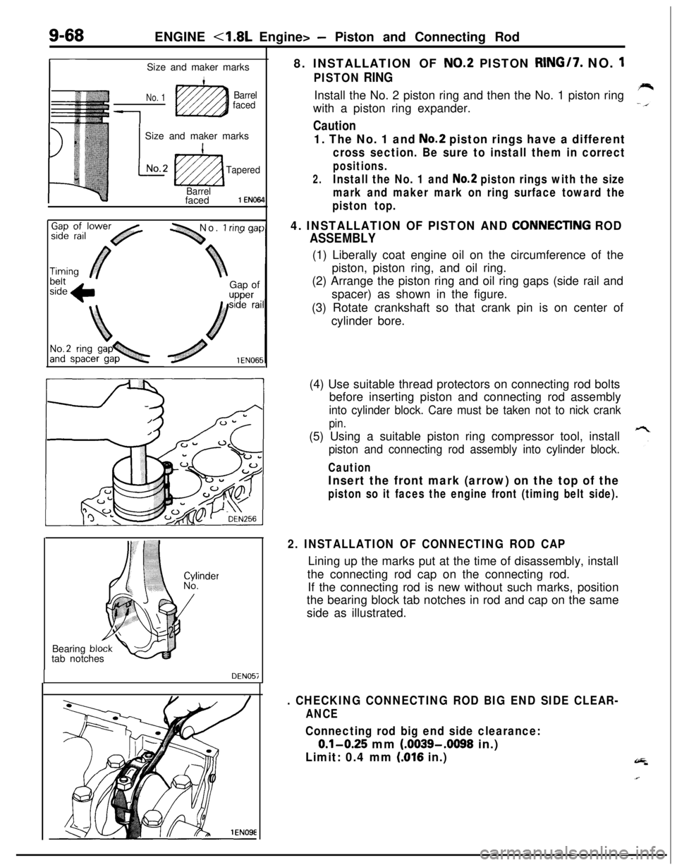
PISTON RINGInstall the No. 2 piston ring and then the No. 1 piston ring
with a piston ring expander.
Caution
1. The No. 1 and No.2 piston rings have a different
cross section. Be sure to install them in correct
positions.
2.Install the No. 1 and No.2 piston rings with the size
mark and maker mark on ring surface toward the
piston top.
4. INSTALLATION OF PISTON AND CONNECTlNG ROD
ASSEMBLY(1) Liberally coat engine oil on the circumference of the
piston, piston ring, and oil ring.
(2) Arrange the piston ring and oil ring gaps (side rail and
spacer) as shown in the figure.
(3) Rotate crankshaft so that crank pin is on center of
cylinder bore.
Bearing
bltab notches
DEN057(4) Use suitable thread protectors on connecting rod bolts
before inserting piston and connecting rod assembly
into cylinder block. Care must be taken not to nick crank
pin.(5) Using a suitable piston ring compressor tool, install
piston and connecting rod assembly into cylinder block.
Caution
Insert the front mark (arrow) on the top of the
piston so it faces the engine front (timing belt side).
2. INSTALLATION OF CONNECTING ROD CAPLining up the marks put at the time of disassembly, install
the connecting rod cap on the connecting rod.
If the connecting rod is new without such marks, position
the bearing block tab notches in rod and cap on the same
side as illustrated.
. CHECKING CONNECTING ROD BIG END SIDE CLEAR-
ANCE
Connecting rod big end side clearance:
0.1-0.25 mm (.0039-.0098 in.)
Limit: 0.4 mm (016 in.)
Page 355 of 1216
ENGINE - Crankshaft, Flwvheel and Drive Plate9-71
3EN30’lrrow mark toward
cap No,
I
RING GEAR (Engine with a manual transaxle)Check the ring gear for worn, damaged or broken teeth.
Replace the ring gear if teeth are faulty, and also check the
starter motor pinion.
Ring Gear Replacement Procedure(1) Strike outer circumference of ring gear at several points.
Caution
The ring gear cannot be removed if it is heated.(2) Install the ring gear on flywheel after heating the ring gear
to
260-280°C (500-536°F) for shrink fit.
FLYWHEEL (Engine with a manual transaxle)
(1) Visually check the clutch disc friction surface of flywheel forridge wear, streaks and seizure. Replace as necessary.
(2) If the flywheel
runout exceeds the limit, replace it.
Limit: 0.13 mm (0051 in.)
DRIVE PLATE (Engine with an automatic transaxle)Replace if deformed, damaged or cracked.
SERVICE POINTS OF REASSEMBLY
NOSUDAA
15. INSTALLATION OF UPPER BEARINGWhen reusing the main bearings, install them in their
original positions by referring to location marking made at
the time of removal.
Be sure that oil holes in bearings align with those in cylinder
block.
13. INSTALLATION OF LOWER BEARINGMake sure that a bearing without oil groove is used as
lower bearing.
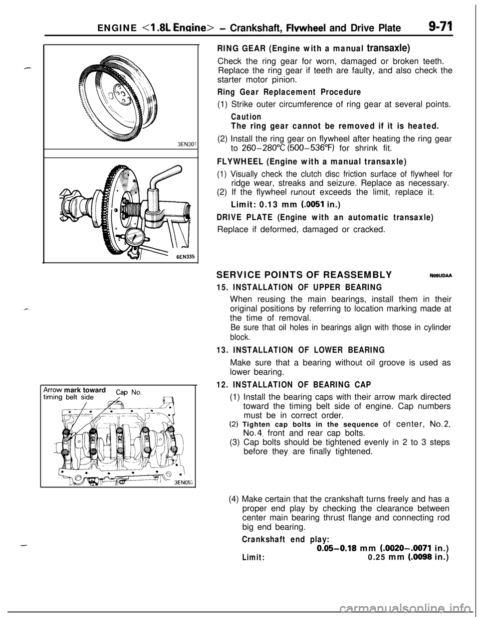
12. INSTALLATION OF BEARING CAP(1) Install the bearing caps with their arrow mark directed
toward the timing belt side of engine. Cap numbers
must be in correct order.(2) Tighten cap bolts in the sequence of center,
No.2,
No.4. front and rear cap bolts.
(3) Cap bolts should be tightened evenly in 2 to 3 steps
before they are finally tightened.
(4) Make certain that the crankshaft turns freely and has a
proper end play by checking the clearance between
center main bearing thrust flange and connecting rod
big end bearing.
Crankshaft end play:
0.05-0.18 mm (.0020-.0071 in.)
Limit:0.25 mm (.0098 in.)
Page 358 of 1216
9-74ENGINE <2.0L DOHC Engine>- Service Adjustment Procedures
ENGINE <2.0L DOHC Engine>
SERVICE ADJUSTMENT PROCEDURES pi
CHECKING COMPRESSION PRESSURENOSFFAH(1) Before checking compression, ensure that engine oil, the
starter motor, and battery are all in good condition.
(2) Start the engine and wait until engine coolant temperature
has risen to
85-95°C (185-205°F).
(3) Stop the engine and pull the spark plug cables.
(4) Remove the spark plugs.
(5) Crank the engine
to. remove any foreign objects in the
cylinders.
Caution
Cover the spark plug holes with shop towel, etc., in
order to keep expelled foreign objects from flying out,and keep away from the holes. When measuring
compression with water, oil, or fuel having entered the
cylinder through a crack, etc., these will come flying
out of the spark plug hole hot and fast, so be sure to
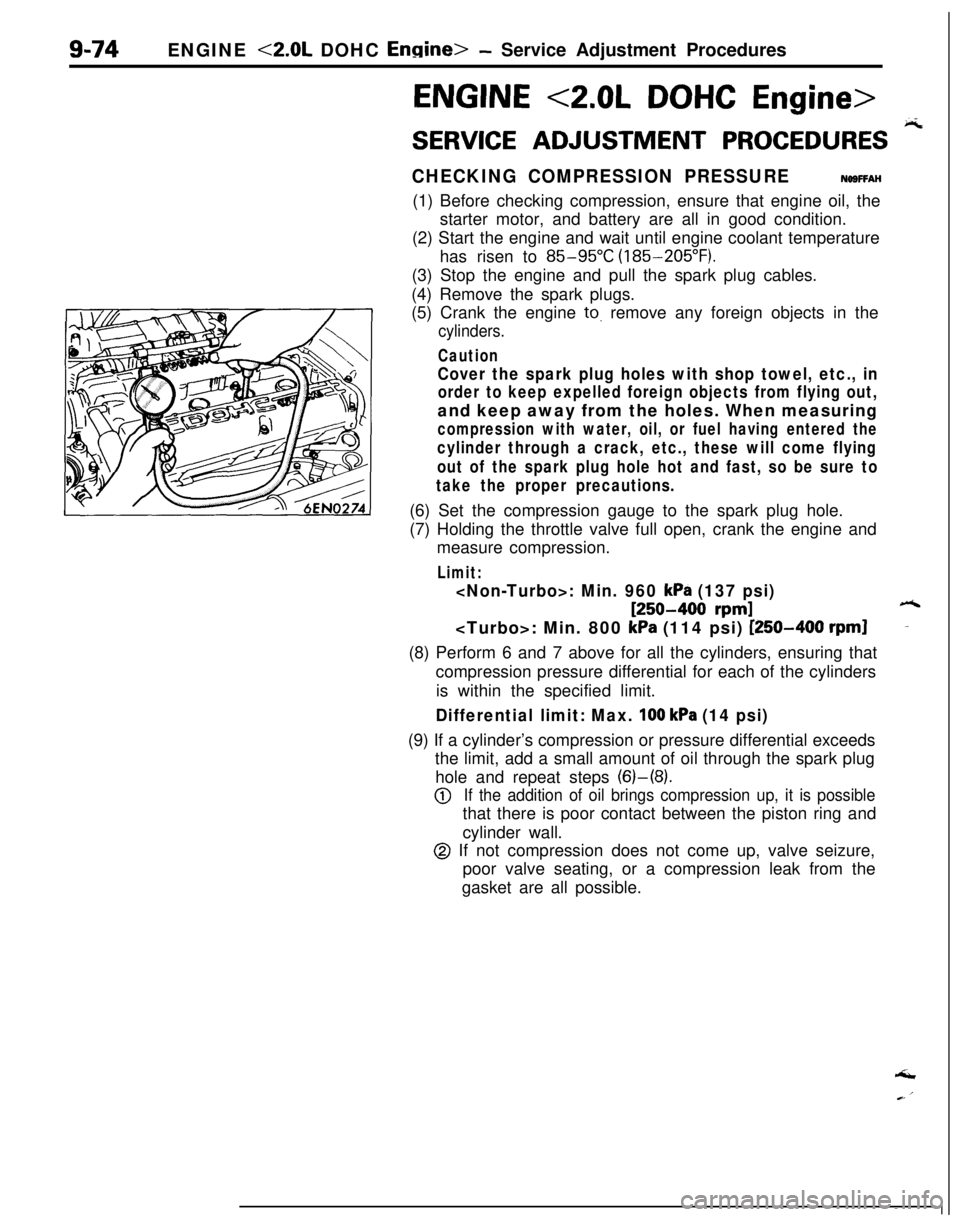
take the proper precautions.(6) Set the compression gauge to the spark plug hole.
(7) Holding the throttle valve full open, crank the engine and
measure compression.
Limit:
[250-400 rpm]6
kPa (114 psi) [250-400 rpml-(8) Perform 6 and 7 above for all the cylinders, ensuring that
compression pressure differential for each of the cylinders
is within the specified limit.
Differential limit: Max. 100 kPa (14 psi)(9) If a cylinder’s compression or pressure differential exceeds
the limit, add a small amount of oil through the spark plug
hole and repeat steps (6)-(8).
@If the addition of oil brings compression up, it is possiblethat there is poor contact between the piston ring and
cylinder wall.
@ If not compression does not come up, valve seizure,
poor valve seating, or a compression leak from the
gasket are all possible.‘I
Page 385 of 1216
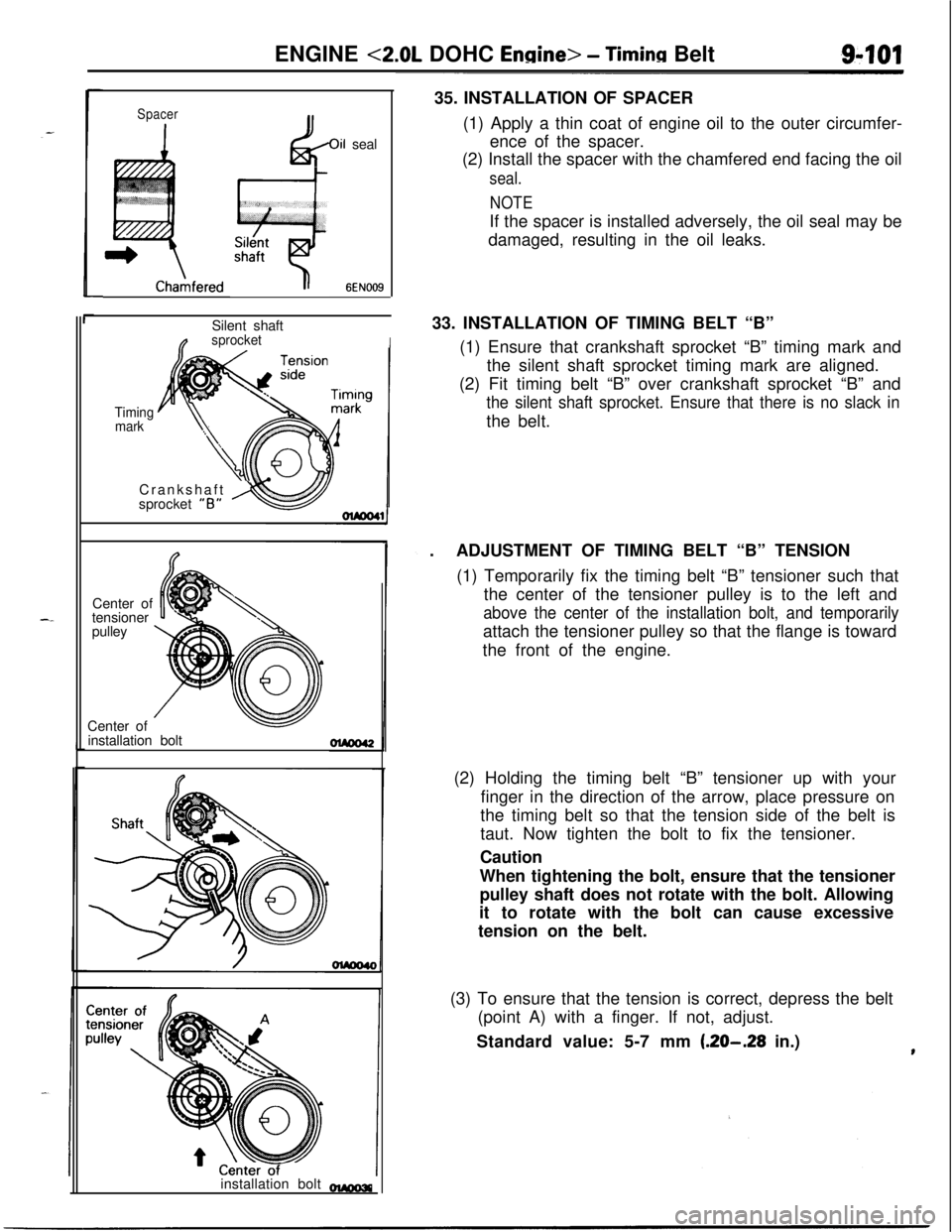
ENGINE <2.0L DOHC Engine> - Timinn Belt
SpacerChahfered
6s
il seal
6EN009Silent shaft
nsprocketI
Timing
markCrankshaft
) ~sprocket “6”Center of
tensioner
pulley
Center of
installation bolt
installation bolt
-35. INSTALLATION OF SPACER
(1) Apply a thin coat of engine oil to the outer circumfer-
ence of the spacer.
(2) Install the spacer with the chamfered end facing the oil
seal.
NOTEIf the spacer is installed adversely, the oil seal may be
damaged, resulting in the oil leaks.
33. INSTALLATION OF TIMING BELT “B”
(1) Ensure that crankshaft sprocket “B” timing mark and
the silent shaft sprocket timing mark are aligned.
(2) Fit timing belt “B” over crankshaft sprocket “B” and
the silent shaft sprocket. Ensure that there is no slack inthe belt.
.ADJUSTMENT OF TIMING BELT “B” TENSION
(1) Temporarily fix the timing belt “B” tensioner such that
the center of the tensioner pulley is to the left and
above the center of the installation bolt, and temporarilyattach the tensioner pulley so that the flange is toward
the front of the engine.
(2) Holding the timing belt “B” tensioner up with your
finger in the direction of the arrow, place pressure on
the timing belt so that the tension side of the belt is
taut. Now tighten the bolt to fix the tensioner.
Caution
When tightening the bolt, ensure that the tensioner
pulley shaft does not rotate with the bolt. Allowing
it to rotate with the bolt can cause excessive
tension on the belt.
(3) To ensure that the tension is correct, depress the belt
(point A) with a finger. If not, adjust.
Standard value: 5-7 mm
(.20-.28 in.)
Page 406 of 1216
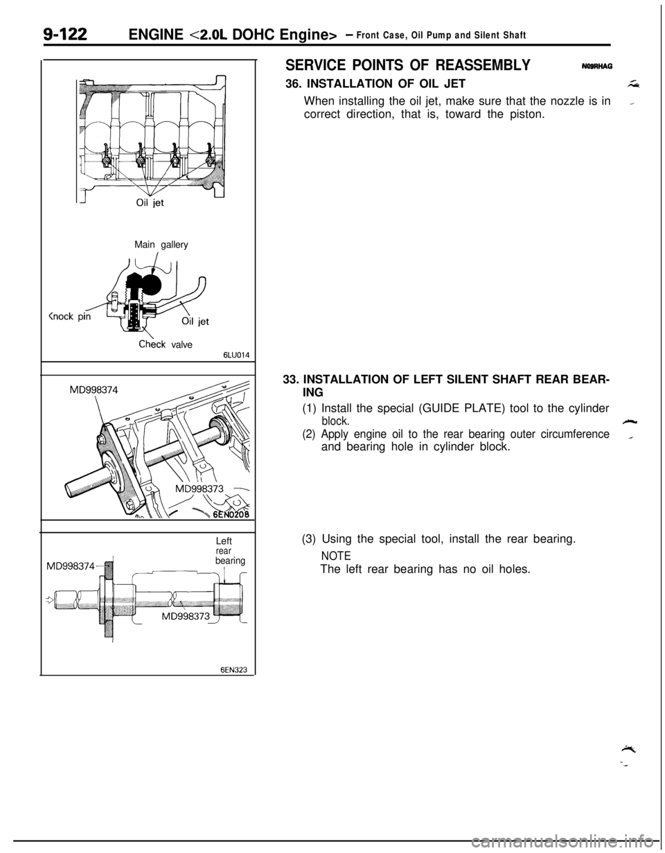
9-122ENGINE <2.0L DOHC Engine>- Front Case, Oil Pump and Silent ShaftMain gallery
rearbearing
6EN323
SERVICE POINTS OF REASSEMBLYNOSRHAG36. INSTALLATION OF OIL JET
;;;itWhen installing the oil jet, make sure that the nozzle is in
_correct direction, that is, toward the piston.
33. INSTALLATION OF LEFT SILENT SHAFT REAR BEAR-
ING
(1) Install the special (GUIDE PLATE) tool to the cylinder
block.k
(2) Apply engine oil to the rear bearing outer circumference1and bearing hole in cylinder block.
(3) Using the special tool, install the rear bearing.
NOTEThe left rear bearing has no oil holes.