service MITSUBISHI ECLIPSE 1991 Service Manual
[x] Cancel search | Manufacturer: MITSUBISHI, Model Year: 1991, Model line: ECLIPSE, Model: MITSUBISHI ECLIPSE 1991Pages: 1216, PDF Size: 67.42 MB
Page 1133 of 1216
BODY - Trims/Headlining23-89
HEADLINING
PEMOVAL AND INSTALLATION
Pm-removal Operationl Removal of Center Pillar Trim
(Refer to
P.23-85.)l Removal of Front Pillar Trim
(Refer to
P.23-85.)l Removal of Guide Rail
(Refer to
P.23-94.)
Post-installation Operation0 Installation of Guide Rail
(Refer to P.23-94.)l Installation of Front Pillar Trim
(Refer to
P.23-85.)l Installation of Center Pillar Trim
(Refer to
P.23-85.)
Vehicles without sunroof
Vehicles with sunroof
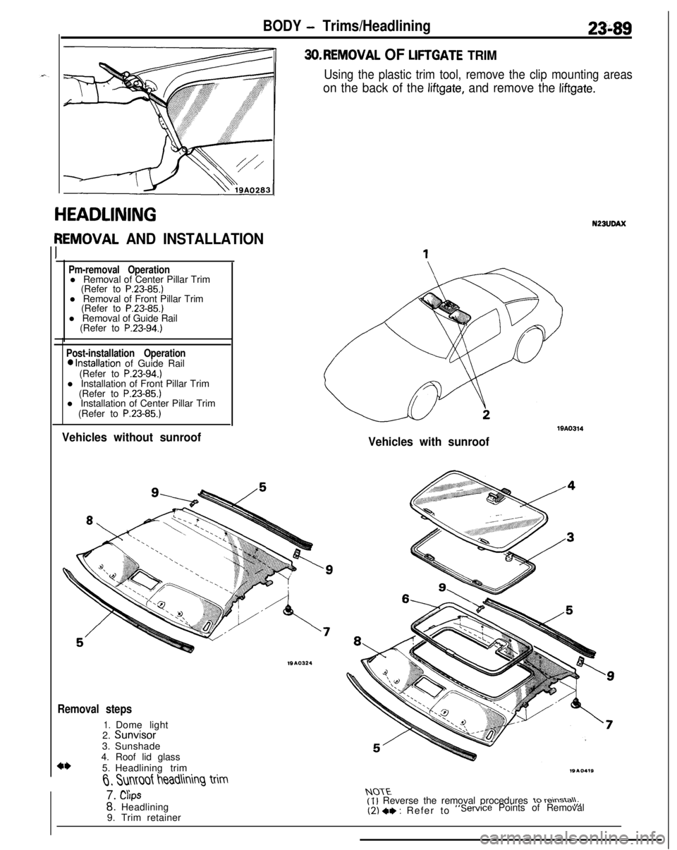
3O.REMOVAL OF LIFTGATE TRIM
Using the plastic trim tool, remove the clip mounting areas
on the back of the liftgate, and remove the liftgate.
Removal steps
1.2.Dome lightSunvisor3.Sunshade
4*4. Roof lid glass
5.Headlining trim
6, Sunmf headlining trim
7. CYlps
8. Headlining
9. Trim retainer
19A0314
N23UDAX
NOTE(I l Reverse the removal procedures to reinsta\\;,(2) +e : Refer to“Service Points of Removal
Page 1134 of 1216
23-90BODY - Headlining/Front Seat
19A0294
FRONT SEAT
REMOVAL AND INSTALLATION17-26
12-19
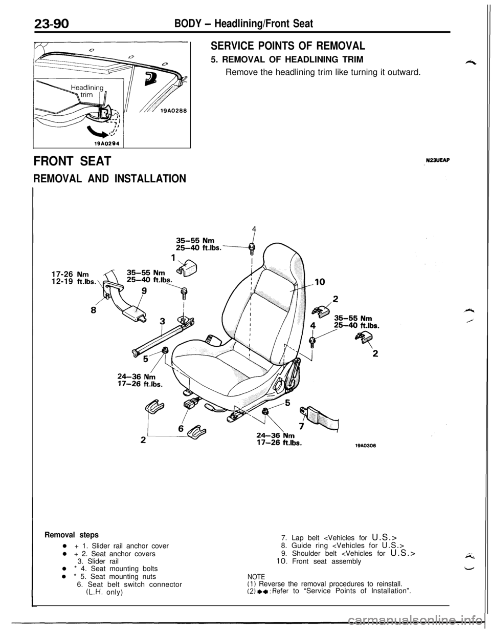
SERVICE POINTS OF REMOVAL5. REMOVAL OF HEADLINING TRIM
Remove the headlining trim like turning it outward.
NZBUEAP4
17-26 ft.lbs.WA0306
Removal stepsl + 1. Slider rail anchor cover
l + 2. Seat anchor covers
3. Slider rail
l * 4. Seat mounting bolts
l * 5. Seat mounting nuts
6. Seat belt switch connector(L.H. only)7. Lap belt
8. Guide ring
9. Shoulder belt
NOTE(1) Reverse the removal procedures to reinstall.(2) +* : Refer to “Service Points of Installation”.
Page 1135 of 1216
\&Front seat’s rearz-2 bracketarea mounting
1Lanchor\
coverForward tabB-B cross-se")
-
BODY - Front Seat23-91
Bolts
19AO308
FrontFront seat forward
installation bracket
A-A cross-section
Forward tab
.)\&Front seat’s rearz-2 bracketarea mounting
1Lanchor\
coverForward tabB-B cross-section19A0124
Slid; railSlide kail’sreararea mounting
bracketWA0302
SERVICE POINTS OF INSTALLATION
5. INSTALLATION OF SEAT MOUNTING NUTW4. SEAT
MOUNTING BOLTS
After checking that the seat adjuster is locked at both sides,
provisionally tighten (in the
A,B,C and D sequence) the seat
mounting nuts and the seat mounting bolts; then fully tighten
at the specified torque.
2. INSTALLATION OF SEAT ANCHOR COVERS
(1) Securely install the front side seat.anchor forward tab tothe front seat forward installation bracket.
(21 Turn the seat anchor cover in the direction indicated by
the arrow, and install the tab at the side part to the holein the bracket side part.
(3) Securely install the rear side seat anchor cover rearwardtab to the front seat rearward installation bracket.
(4) Turn the seat anchor cover in the direction indicated by
the arrow and insert the side tabs into the holes in the
front seat rearward installation bracket side part.1. INSTALLATION OF SLIDER RAIL ANCHOR COVERS
Securely the rear
pawl of the slider rail anchor cover to the
mounting bracket on the rear of the slider rail, and mount theslider rail anchor cover, turning its front area.
Page 1137 of 1216
BODY - Rear Seat23-93
REAR SEATN23UFAN
.~x REMOVAL AND INSTALLATION4-6 Nm
3-4
ft.lbs.
A12-19
ft.lbs.12-19
ft.lbs.
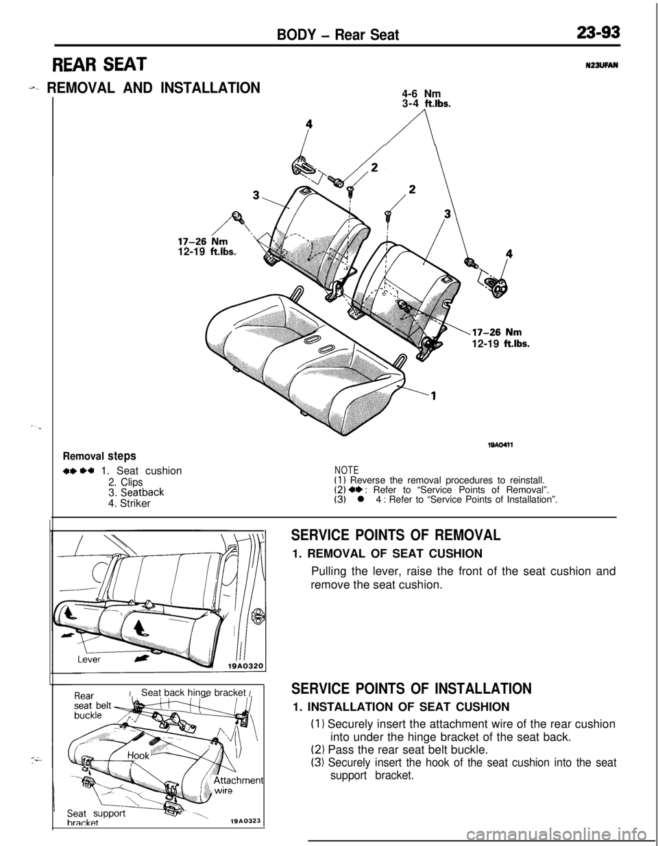
Removal steps
w w 1. Seat cushion
2. Clips3. Seatback4. Striker
19AO411
NOTE(1) Reverse the removal procedures to reinstall.(2) +* : Refer to “Service Points of Removal”.(3) l 4 : Refer to “Service Points of Installation”.
ISeat back hinge bracket I
Seatbracket
1910323
SERVICE POINTS OF REMOVAL1. REMOVAL OF SEAT CUSHION
Pulling the lever, raise the front of the seat cushion and
remove the seat cushion.
SERVICE POINTS OF INSTALLATION1. INSTALLATION OF SEAT CUSHION
(1) Securely insert the attachment wire of the rear cushion
into under the hinge bracket of the seat back.
(2) Pass the rear seat belt buckle.
(3) Securely insert the hook of the seat cushion into the seat
support bracket.
Page 1138 of 1216
23-94BODY - Seat Belt
SEAT BELT
REMOVAL AND INSTALLATION
N23UQBF
/
//35-55 Nm
25-40 ft.lbs.U/16 in. x 25 mm
bolts) ,n(8 x 20 mm
bolts)
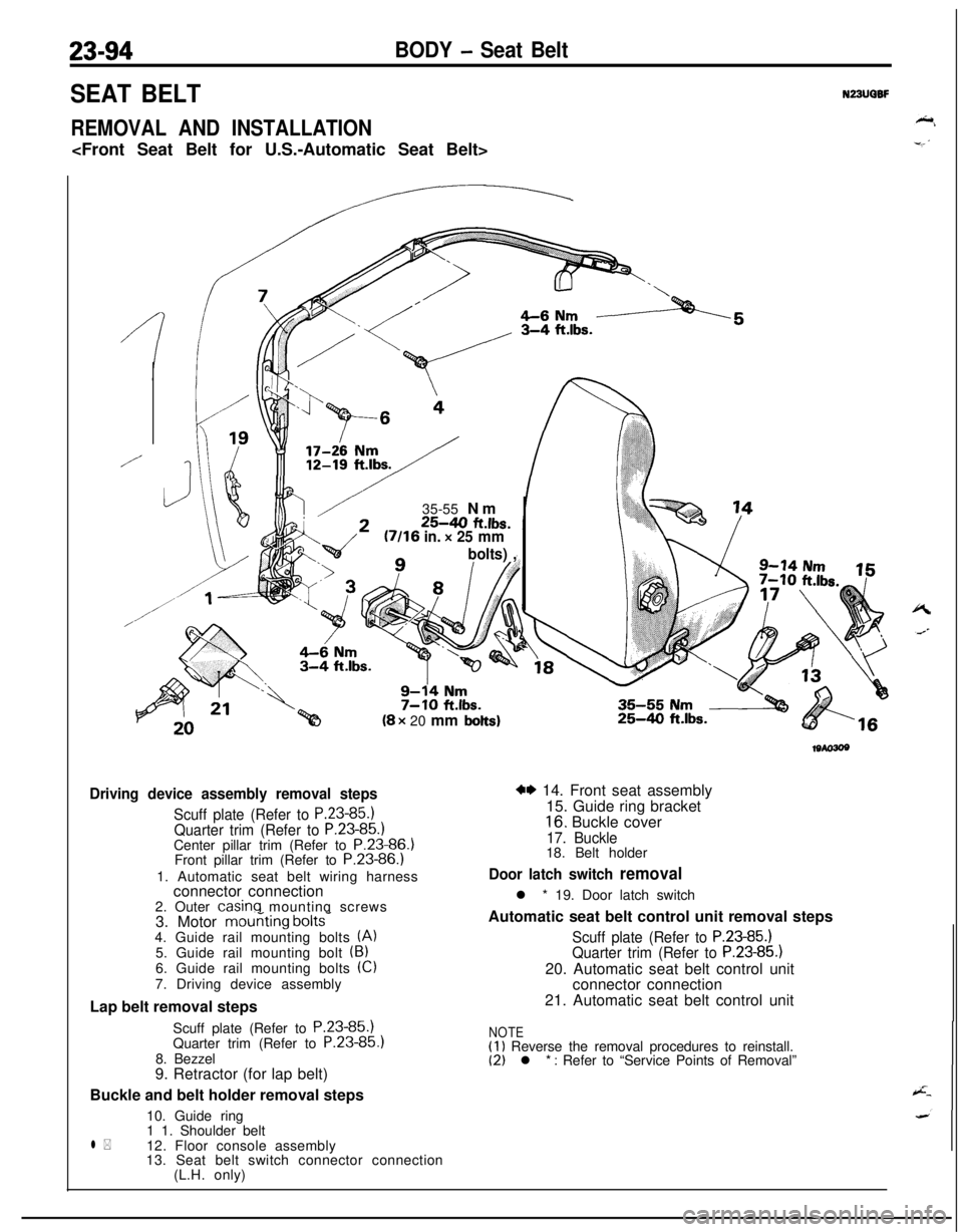
Driving device assembly removal steps
Scuff plate (Refer to P.23-85.1Quarter trim (Refer to P.23-85.)Center pillar trim (Refer to P.23-86.)
Front pillar trim (Refer to P.23-86.)
1. Automatic seat belt wiring harness
connector connection
2. Outer
casinq mounting screws
3. Motor mouriting bolts-4. Guide rail mounting bolts (A)5. Guide rail mounting bolt (B)6. Guide rail mounting bolts (Cl
7. Driving device assembly
Lap belt removal steps
Scuff plate (Refer to P.23-85.)
Quarter trim (Refer to P.23-85
8. Bezzel
9. Retractor (for lap belt)
Buckle and belt holder removal steps
10. Guide ring
l *1 1. Shoulder belt
12. Floor console assembly
13. Seat belt switch connector connection
(L.H. only)
25-4.0 ft.lbs.
w 14. Front seat assembly
15. Guide ring bracket
16. Buckle cover
17. Buckle18. Belt holder
Door latch switch removall * 19. Door latch switch
Automatic seat belt control unit removal steps
Scuff plate (Refer to P.23-85.)Quarter trim (Refer to P.23-85.)20. Automatic seat belt control unit
connector connection
21. Automatic seat belt control unit
NOTE(1) Reverse the removal procedures to reinstall.(2) l * : Refer to “Service Points of Removal”
Page 1139 of 1216
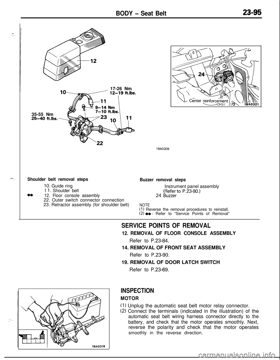
BODY - Seat Belt23-9535-55 Nm
25-40 ft.lbs.\17-26 Nm
Shoulder belt removal steps
10. Guide ring
1 1. Shoulder beltc*12. Floor console assembly22. Outer switch connector connection
23. Retractor assembly (for shoulder belt)
19A0309
Buzzer removal stepsInstrument panel assembly24
(gy;ZfieerrtO P.23-80.)
NOTE(1) Reverse the removal procedures to reinstall.(2) +e : Refer to “Service Points of Removal”
19A0319
SERVICE POINTS OF REMOVAL
12. REMOVAL OF FLOOR CONSOLE ASSEMBLYRefer to
P.23-84.14. REMOVAL OF FRONT SEAT ASSEMBLY
Refer to
P.23-90.19. REMOVAL OF DOOR LATCH SWITCH
Refer to
P.23-69.
INSPECTION
MOTOR
(1) Unplug the automatic seat belt motor relay connector.
(2) Connect the terminals (indicated in the illustration) of the
automatic seat belt wiring harness connector directly to the
battery, and check that the motor operates smoothly. Next,reverse the polarity and check that the motor operates
smoothly in the reverse direction.
Page 1142 of 1216
23-98BODY - Seat Belt
\9-14 Nms-55 Nm
7-10 ft.lbs.25-40 ft.lbs.
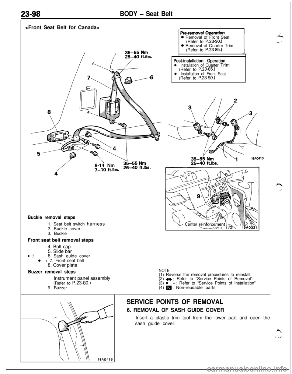
Pre-removal Operation0 Removal of Front Seat
(Refer to
P.23-90.)0 Removal of Quarter Trim
(Refer to
P.23-85.)
Post-installation Operationl Installation of Quarter Trim(Refer to P.23-85.)l Installation of Front Seat(Refer to P.23-90.)
Buckle removal steps1. Seat belt switch harness
2. Buckle cover
3. Buckle
Front seat belt removal steps
4. Bolt cap
5. Slide bar
l +6. Sash guide cover
l + 7. Front seat belt
8. Cover plate
Buzzer removal stepsInstrument panel assembly
(Refer to P.23-80.)
9. BuzzerNOTE(1) Reverse the removal procedures to reinstall.
(2)
+e : Refer to “Service Points of Removal”.
(3) l + : Refer to “Service Points of Installation”
(4) m : Non-reusable parts
SERVICE POINTS OF REMOVAL6. REMOVAL OF SASH GUIDE COVER
Insert a plastic trim tool from the lower part and open the
sash guide cover.
Page 1143 of 1216
BODY - Seat Belt23-99
19AO239
I ITest bulb 2tI
I I
INSPECTION
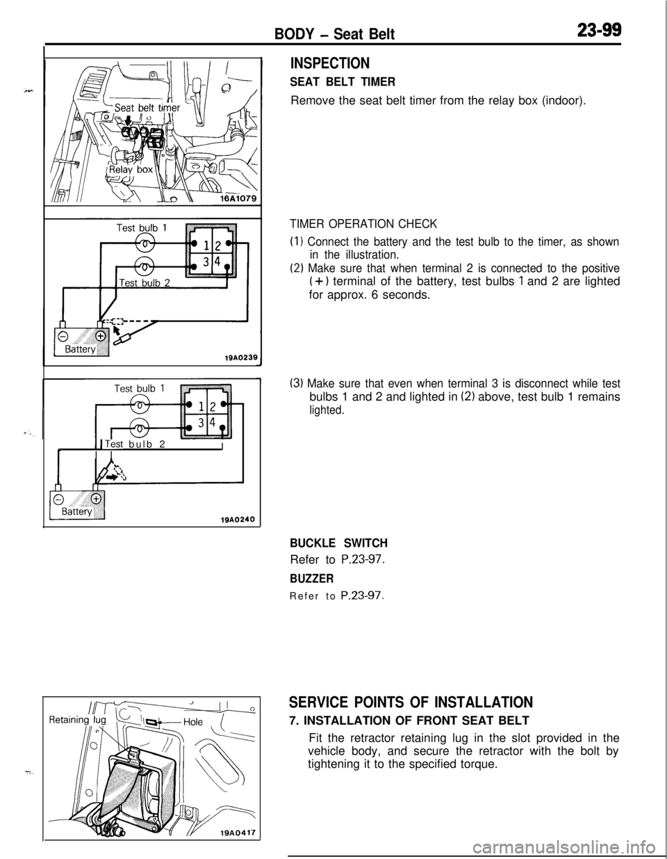
SEAT BELT TIMERRemove the seat belt timer from the relay box (indoor).
TIMER OPERATION CHECK(I
1 Connect the battery and the test bulb to the timer, as shown
in the illustration.
(2) Make sure that when terminal 2 is connected to the positive
(+) terminal of the battery, test bulbs 1 and 2 are lighted
for approx. 6 seconds.
(3) Make sure that even when terminal 3 is disconnect while testbulbs 1 and 2 and lighted in
(2) above, test bulb 1 remains
lighted.
BUCKLE SWITCHRefer to
P.23-97.
BUZZERRefer to
P.23-97.
SERVICE POINTS OF INSTALLATION7. INSTALLATION OF FRONT SEAT BELT
Fit the retractor retaining lug in the slot provided in the
vehicle body, and secure the retractor with the bolt by
tightening it to the specified torque.
Page 1144 of 1216
23-100BODY - Seat Belt
35-55 Nm
25-40 ft.lbs.
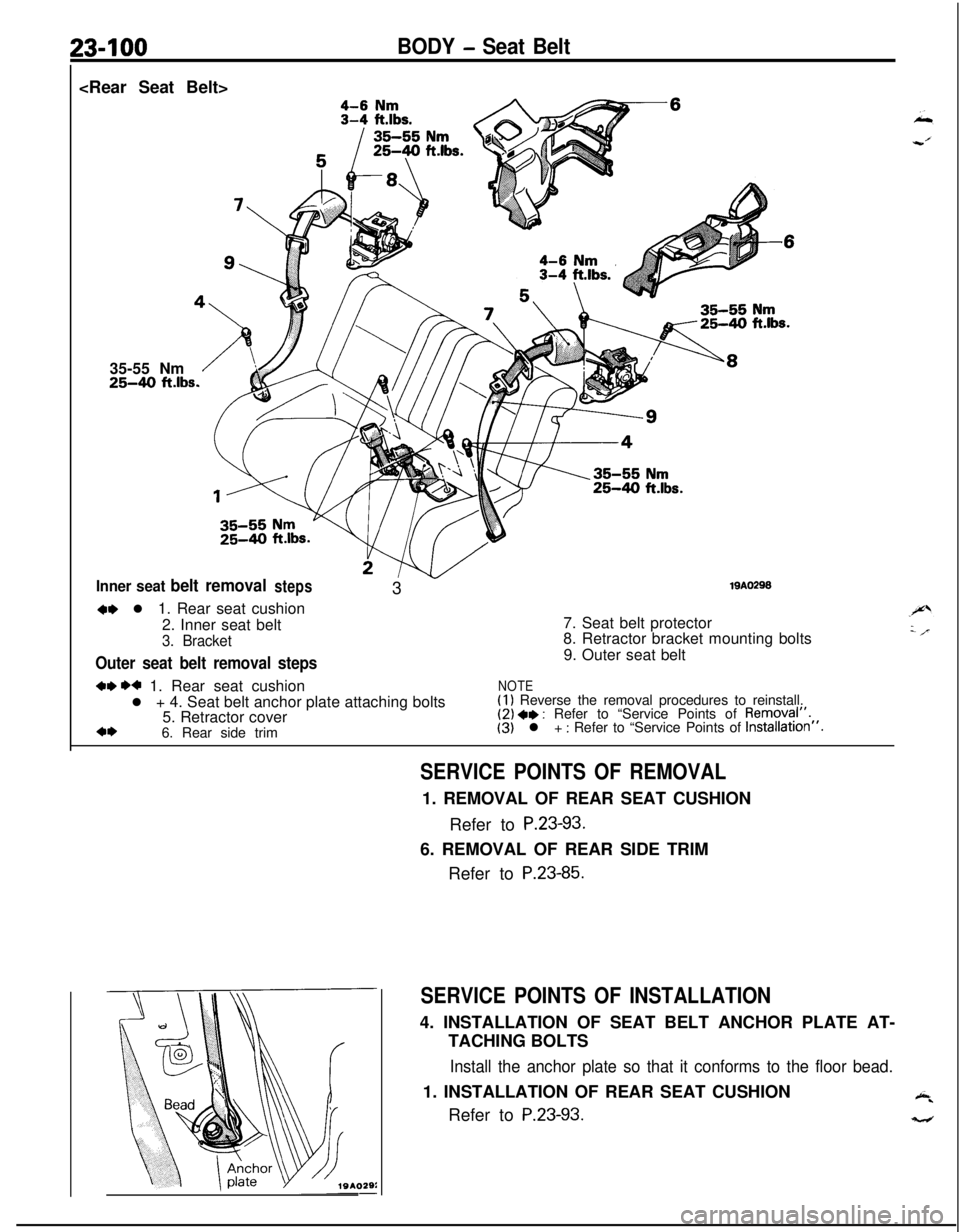
Inner seat belt removalsteps319A029S
M l 1. Rear seat cushion
2. Inner seat belt
3. Bracket
Outer seat belt removal steps7. Seat belt protector
8. Retractor bracket mounting bolts
9. Outer seat belt
w H 1. Rear seat cushionNOTEl + 4. Seat belt anchor plate attaching bolts(I 1 Reverse the removal procedures to reinstall.
5. Retractor cover(2) ** : Refer to “Service Points of Removql”.
*I)6. Rear side trim(3) l + : Refer to “Service Points of Installation”.
SERVICE POINTS OF REMOVAL1. REMOVAL OF REAR SEAT CUSHION
Refer to
P.23-93.6. REMOVAL OF REAR SIDE TRIM
Refer to
P.23-85.
SERVICE POINTS OF INSTALLATION4. INSTALLATION OF SEAT BELT ANCHOR PLATE AT-
TACHING BOLTS
Install the anchor plate so that it conforms to the floor bead.1. INSTALLATION OF REAR SEAT CUSHION
Refer to
P.23-93.
Page 1145 of 1216
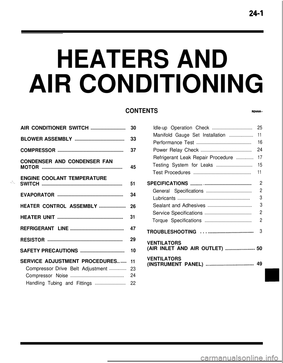
24-l
HEATERS ANDAIR CONDITIONING
CONTENTSN24M--AIR CONDITIONER SWITCH
..........................30BLOWER ASSEMBLY
.....................................33
COMPRESSOR.................................................37CONDENSER AND CONDENSER FAN
MOTOR............................................................45ENGINE COOLANT TEMPERATURE
-‘-.,SWITCH............................................................51
EVAPORATOR.................................................
34
HEATERCONTROLASSEMBLY....................
26HEATER UNIT
.................................................31
REFRIGERANTLINE........................................47
RESISTOR........................................................29SAFETY PRECAUTIONS
.................................10SERVICE ADJUSTMENT PROCEDURES..
.....11Compressor Drive
Belt Adjustment
.............
23
CompressorNoise........................................24
Handling
TubingandFittings.......................22Idle-up
OperationCheck..............................25Manifold
GaugeSetInstallation..................11Performance Test
.........................................16Power Relay Check
......................................24Refrigerant Leak Repair Procedure
.............17
TestingSystemforLeaks...........................15Test Procedures
...........................................11
SPECIFICATIONS.............................................2
General Specifications..................................2
Lubricants......................................................3Sealant and Adhesives
.................................3Service Specifications
...................................2
TorqueSpecifications...................................2
TROUBLESHOOTING. . . ..a................................3
VENTILATORS(AIR INLET AND AIR OUTLET)
..,....s............. 50
VENTILATORS(INSTRUMENT PANEL)
..,...................*...........49