boot MITSUBISHI ECLIPSE 1991 Service Manual
[x] Cancel search | Manufacturer: MITSUBISHI, Model Year: 1991, Model line: ECLIPSE, Model: MITSUBISHI ECLIPSE 1991Pages: 1216, PDF Size: 67.42 MB
Page 3 of 1216
INTRODUCTION AND MASTER TROUBLESHOOTING - How to Use This Manual3Page number
Group title
IIndicates the incidental operation to be
performed before removal or after
installa-
52444BRAKES-Roar Brake Wlmd Cylinder
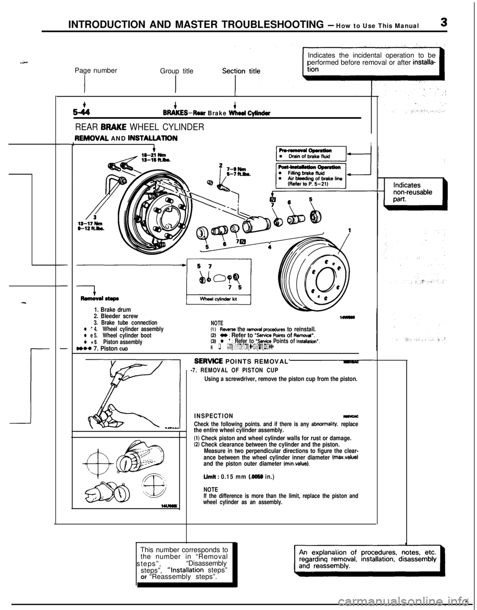
REAR BRAKE WHEEL CYLINDER
-
-
-
3ENjOVAL AND lNSTAU.AllONII
Remwal stepa
1. Brake drum
2. Bleeder screw
3. Brake tube connectionl * 4.Wheel cylinder assemblyl e 5.Wheel cylinder bootl + 6.Piston assemblyn** 7. Piston cue
NOTEI1 lReverse the removal procedures to reinstall.12)M : Refer to ‘Service Points of Aemcval”.(3)l * : Refer to ‘Service Points of Installation’.14) q :Nc+-r-reusab(epatts
SERWE POINTS REMOVAL’
-7. REMOVAL OF PISTON CUP
Using a screwdriver, remove the piston cup from the piston.
INSPECTION-
Check the following points. and if there is any abnormality, replacethe entire wheel cylinder assembly.
(1) Check piston and wheel cylinder walls for rust or damage.(2) Check clearance between the cylinder and the piston.
Measure in two perpendicular directions to figure the clear-
ance between the wheel cylinder inner diameter
fmax.value)and the piston outer diameter (minvalue).
Limit : 0.15 mm (4059 in.)
NOTE
If the difference is more than the limit, replace the piston and
wheel cylinder as an assembly.This number corresponds to
the number in “Removal
steps”,“Disassembly
steps”,“Installation steps”
or “Reassembly steps”.
Page 35 of 1216
LUBRICATION AND’ I
MAINTENANCE
CONTENTSGENERAL INFORMATION
..............................2MAINTENANCE SERVICE
...............................7Air
CleanerElement.....................................7Automatic Transaxle....................................
11Ball Joint and Steering Linkage Seals
........13Brake Hoses
.................................................12
DiscBrakePads...........................................12-lbDrive Belt (For Water Pump and
Alternator).....................................................8
DriveShaftBoots.........................................13
EngineCoolant.............................................12
EngineOil.....................................................9
EngineOilFilter...........................................9Exhaust System
............................................13
FuelHose.....................................................7
FuelSystem.................................................7
ManualTransaxle..........................................10
RearAxle......................................................13
SparkPlugs...................................................8
TimingBelt......................................................8RECOMMENDED LUBRICANTS AND
LUBRICANT CAPACITIES TABLE
..................4SCHEDULED MAINTENANCE TABLE
............3
Page 37 of 1216
LUBRICATION AND MAINTENANCE - Scheduled MaintenanCe Table. &3
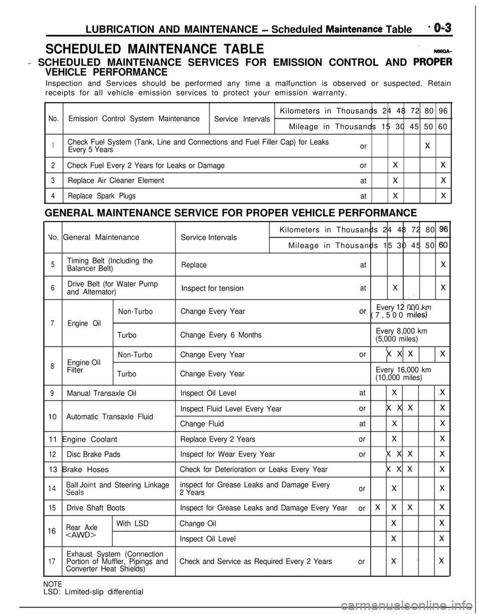
SCHEDULED MAINTENANCE TABLE1
- SCHEDULED MAINTENANCE SERVICES FOR EMISSION CONTROL AND PRO;;
VEHICLE PERFORMANCEInspection and Services should be performed any time a malfunction is observed or suspected. Retain
receipts for all vehicle emission services to protect your emission warranty.
Kilometers in Thousands 24 48 72 80 96
No.Emission Control System Maintenance
Service IntervalsMileage in Thousands 15 30 45 50 60
1Check Fuel System (Tank, Line and Connections and Fuel Filler Cap) for Leaks
Every 5 YearsorX
2Check Fuel Every 2 Years for Leaks or DamageorXX
3Replace Air Cleaner Element
atXX
4Replace Spark Plugs
atXXGENERAL MAINTENANCE SERVICE FOR PROPER VEHICLE PERFORMANCE
Yo. General Maintenance
Service IntervalsKilometers in Thousands 24 48 72 80 9cMileage in Thousands 15 30 45 50
6C
5Timing Belt (Including theBalancer Belt)ReplaceatX
6Drive Belt (for Water Pump
and Alternator)Inspect for tensionatXX.’
Non-TurboChange Every YearEvery 12 000 kmOr (7,500 miles).
7Engine Oil
TurboChange Every 6 MonthsEvery 8,000 km
(5,000 miles)
Non-TurboChange Every Yearor X X XX
8Engine Oil
Filter
TurboChange Every YearEvery 16,000 km
(10,000 miles)
9Manual Transaxle OilInspect Oil LevelatX.X
Inspect Fluid Level Every Yearor X X XX
10Automatic Transaxle Fluid
Change FluidatXX11 Engine Coolant
Replace Every 2 YearsorXX
12Disc Brake PadsInspect for Wear Every Yearor X X XX13 Brake Hoses
Check for Deterioration or Leaks Every YearX X XX
l 4Beiloint and Steering Linkageinspect for Grease Leaks and Damage Every
2 YearsorXX
15Drive Shaft BootsInspect for Grease Leaks and Damage Every Yearor XXXX
Rear Axle
With LSDChange OilXX1 6
Exhaust System (Connection17Portion of Muffler, Pipings andCheck and Service as Required Every 2 Yearsorx -xConverter Heat Shields)
NOTELSD: Limited-slip differential
Page 47 of 1216
LUBRICATION AND MAINTENANCE - Maintenance Serviceo-13
OOAOlB6
13.BRAKE HOSES (Check for deteriorati.on or
leaks)NwBBnAs
Inspection of brake hoses and tubing should be included inall brake service operations.
The hoses should be checked for:
1. Correct length, severe surface cracking, pulling, scuf-
fing or worn spots. (If the fabric casing of the hoses is
exposed by cracks of abrasion in the rubber hose cover,
the hoses should be replaced. Eventual deterioration ofhose may occur with possible bursting failure.)
2. Faulty installation, casing twisting or interference with
wheel, tire of chassis.
14.BALL JOINT AND STEERING LINKAGE SEALS
(Inspect for grease leaks and damage)
NWSBJAb1. These components, which are permanently lubricated
at the factory, do not require periodic lubrication.
Damaged seals and boots should be replaced to
prevent leakage or contamination of the grease.
2. Inspect the dust cover and boots for proper sealing,
leakage and damage. Replace them if defective.
15.DRIVE SHAFT BOOTS (Inspect for grease leaksand damage)
NWSBJAc1. These components, which are permanently lubricated
at the factory, do not require periodic lubrication.
Damaged boots should be replaced to prevent leakage
or contamination of the grease.
2. Inspect the boots for proper sealing, leakage and
damage. Replace it if defective.
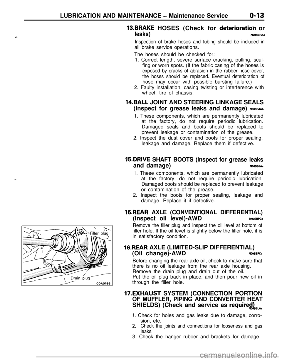
16.REAR AXLE (CONVENTIONAL DIFFERENTIAL)(Inspect oil level)-AWD
NWSBFCa
Remove the filler plug and inspect the oil level at bottom offiller hole. If the oil level is slightly below the filler hole, it is
in satisfactory condition.
16.REAR AXLE (LIMITED-SLIP DIFFERENTIAL)
(Oil change)-AWD
N66SBFCcBefore changing the rear axle oil, check to make sure that
there is no oil leakage from the rear axle housing.
Remove the drain plug and drain out of the oil.
Put the oil plug back in place, and then pour new oil in
through the filler hole.
17.EXHAUST SYSTEM (CONNECTION PORTION
OF MUFFLER, PIPING AND CONVERTER HEATSHIELDS) (Check and service as
require$dBu.
1. Check for holes and gas leaks due to damage, corro-
sion, etc.
2.Check the joints and connections for looseness and gas
leaks.3. Check the hanger rubber and brackets for damage.
Page 52 of 1216
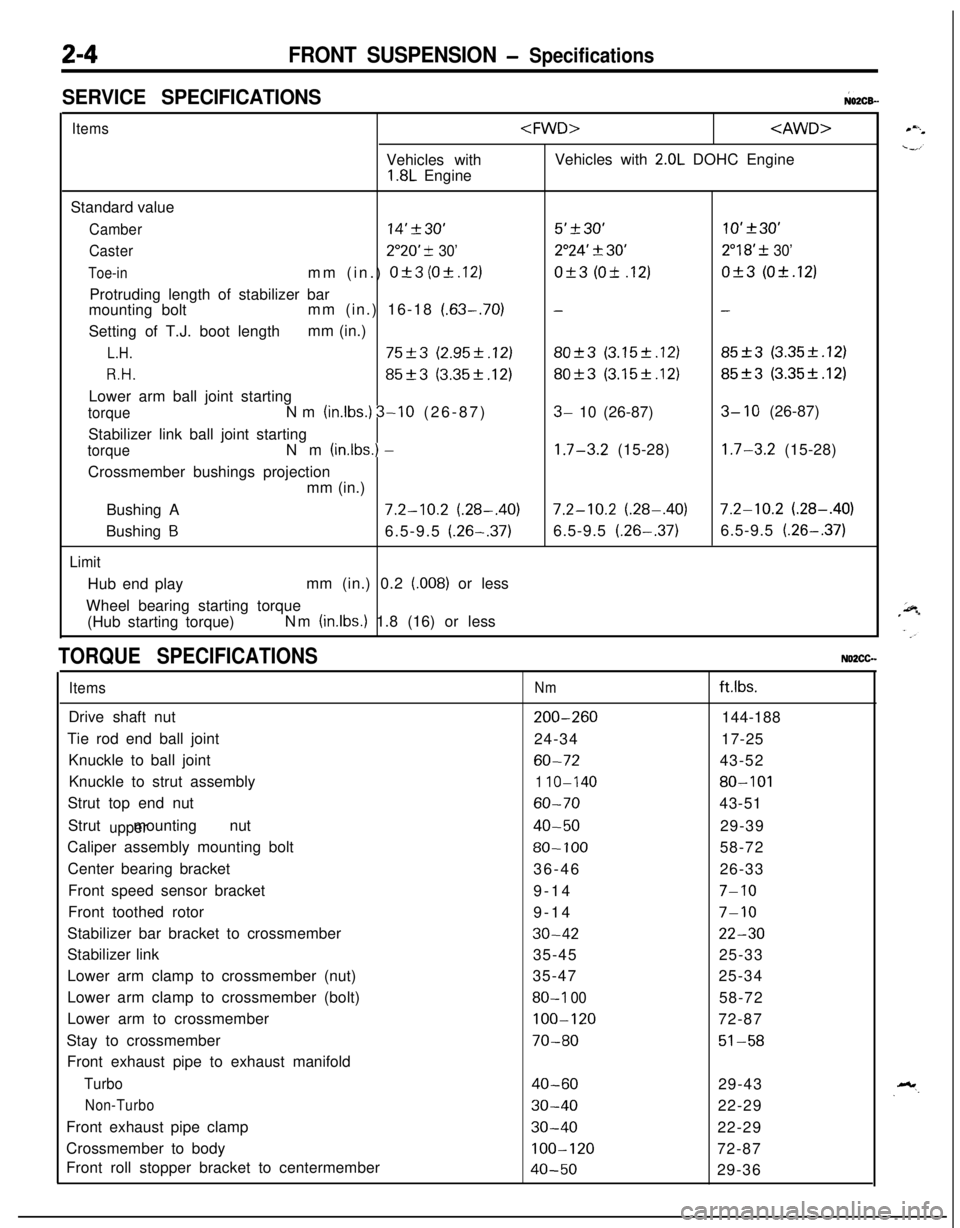
2-4FRONT SUSPENSION - Specifications
SERVICE SPECIFICATIONS;02CB-
ItemsVehicles with
1.8L Engine
2.0L DOHC Engine
Standard value
Camber14’230’5’+30’10’+30’
Caster2”20’ -t 30’2”24’ 3130’2”18’ f 30’
Toe-inmm (in.) Of3 (Ok.12)Of3 (Ok .12)Of3 (Ok.12)
Protruding length of stabilizer bar
mounting boltmm (in.) 16-18
(.63-.70)--Setting of T.J. boot lengthmm (in.)
L.H.75+3 (2.95f.12)80-+3 (3.15f.12)85_+3 (3.35k.12)
R.H.85f3 (3.35k.12)80+3 (3.15k.12)85f3 (3.35f.12)Lower arm ball joint starting
torqueNm (in.lbs.) 3-10 (26-87)3- 10 (26-87)3- 10 (26-87)
Stabilizer link ball joint starting
torqueNm (inlbs.) -1.7-3.2 (15-28)1.7-3.2 (15-28)
Crossmember bushings projection
mm (in.)
Bushing A
7.2-10.2 (.28-.40)7.2-10.2 (.28-.40)7.2-10.2 (.28-.40)
Bushing
B6.5-9.5 (.26-.37)6.5-9.5 (.26-.37)6.5-9.5 (.26-.37)
LimitHub end playmm (in.) 0.2
(.008) or less
Wheel bearing starting torque
(Hub starting torque)Nm
(in.lbs.) 1.8 (16) or less
TORQUE SPECIFICATIONSNO2CG.
ItemsDrive shaft nut
Tie rod end ball joint
Knuckle to ball joint
Knuckle to strut assembly
Strut top end nut
Strut mounting nut
upperCaliper assembly mounting bolt
Center bearing bracket
Front speed sensor bracket
Front toothed rotor
Stabilizer bar bracket to crossmember
Stabilizer link
Lower arm clamp to crossmember (nut)
Lower arm clamp to crossmember (bolt)
Lower arm to crossmember
Stay to crossmember
Front exhaust pipe to exhaust manifold
Turbo
Non-TurboFront exhaust pipe clamp
Crossmember to body
Front roll stopper bracket to centermember
Nmftlbs.
200-260144-188
24-3417-25
60-7243-52
1 IO-14080-101
60-7043-51
40-5029-39
80-10058-72
36-4626-33
9-14
7-109-14
7-10
30-4222-3035-4525-33
35-4725-34
80-I 0058-72
100-12072-87
70-8051-58
40-6029-43
30-4022-29
30-4022-29
100-12072-87
40-5029-36
Page 53 of 1216
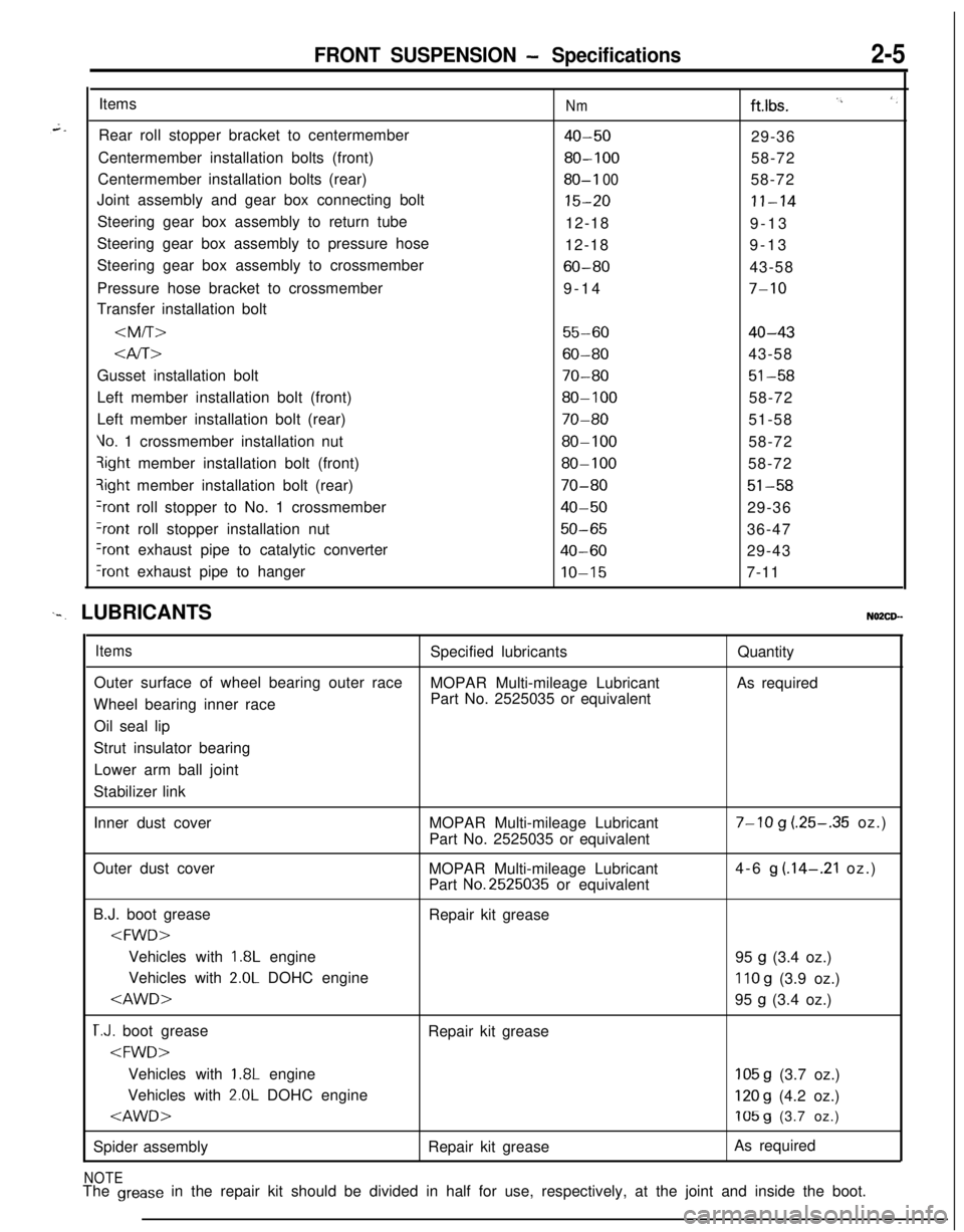
FRONT SUSPENSION - Specifications2-5Items
Rear roll stopper bracket to centermember
Centermember installation bolts (front)
Centermember installation bolts (rear)
Joint assembly and gear box connecting bolt
Steering gear box assembly to return tube
Steering gear box assembly to pressure hose
Steering gear box assembly to crossmember
Pressure hose bracket to crossmember
Transfer installation bolt
Nmftlbs. I’, ‘,
40-5029-36
80-10058-72
80-I 0058-72
15-20II-1412-18
9-13
12-189-13
60-8043-58
9-14
7-10
55-6040-43
Gusset installation bolt
70-8051-58Left member installation bolt (front)
80-10058-72
Left member installation bolt (rear)
70-8051-58
Vo. 1 crossmember installation nut80-10058-72qight member installation bolt (front)
80-10058-72?ight member installation bolt (rear)
70-8051-58
+ont roll stopper to No. 1 crossmember40-5029-36
?ont roll stopper installation nut50-6536-47
Iront exhaust pipe to catalytic converter40-6029-43
‘rant exhaust pipe to hangerIO-157-11
‘-. LUBRICANTSNO2CD--
ItemsSpecified lubricantsQuantity
Outer surface of wheel bearing outer race
MOPAR Multi-mileage LubricantAs required
Wheel bearing inner racePart No. 2525035 or equivalent
Oil seal lip
Strut insulator bearing
Lower arm ball joint
Stabilizer link
Inner dust coverMOPAR Multi-mileage Lubricant
Part No. 2525035 or equivalent
7-10 g (.25-.35 oz.)
Outer dust cover
MOPAR Multi-mileage Lubricant
Part
No.2525035 or equivalent4-6
g (.14-.21 oz.)
B.J. boot grease
Repair kit grease
1.8L engine
95 g (3.4 oz.)
Vehicles with
2.0L DOHC engine110 g (3.9 oz.)
T.J. boot grease
Repair kit grease
1.8L engine105 g (3.7 oz.)
Vehicles with
2.0L DOHC engine120 g (4.2 oz.)
Spider assemblyRepair kit greaseAs required
NOTEThe grease in the repair kit should be divided in half for use, respectively, at the joint and inside the boot.
Page 63 of 1216
FRONT SUSPENSION - Hub and Knuckle/Drive Shaft245
M B990985
llR0066
DRIVE SHAFT
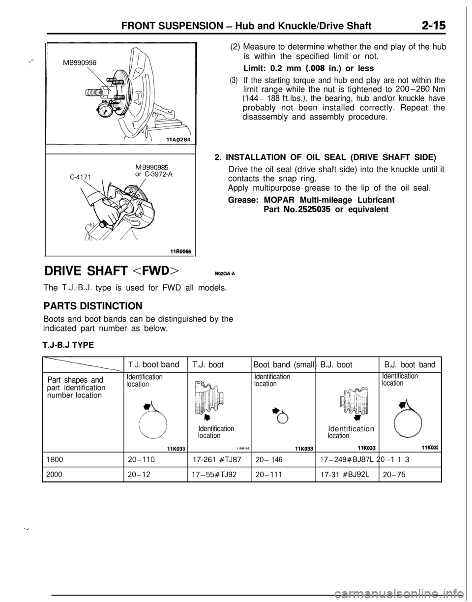
is within the specified limit or not.
Limit: 0.2 mm
(.008 in.) or less
(3)If the starting torque and hub end play are not within thelimit range while the nut is tightened to
200-260 Nm
(144- 188 ftlbs.), the bearing, hub and/or knuckle haveprobably not been installed correctly. Repeat the
disassembly and assembly procedure.
The
T.J.-B.J. type is used for FWD all models.
PARTS DISTINCTION
Boots and boot bands can be distinguished by the
indicated part number as below.
T.J-B.J TYPE2. INSTALLATION OF OIL SEAL (DRIVE SHAFT SIDE)
Drive the oil seal (drive shaft side) into the knuckle until it
contacts the snap ring.
Apply multipurpose grease to the lip of the oil seal.
Grease: MOPAR Multi-mileage Lubricant
Part No.2525035 or equivalent
Part shapes andpart identification
number location
T.J. boot bandT.J. bootBoot band (small) B.J. bootB.J. boot band
IdentificationIdentificationIdentificationlocation
locationlocation
1800
2000
IdentificationIdentificationlocation
location
llK033llR0156llK033llK033llK03:
20-I 1017-261 #TJ87.20- 14617-249#BJ87L 20-I 13
20-1217-55#TJ9220-11117-31 #BJ92L20-75
Page 65 of 1216
FRONT SUSPENSION - Drive Shaft247Pry bar
13E526
12RO426Cotter pin
/
/HubllR0015
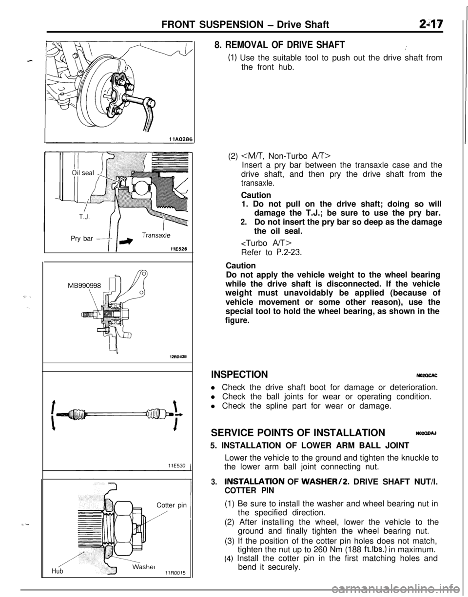
8. REMOVAL OF DRIVE SHAFT.’
(1) Use the suitable tool to push out the drive shaft from
the front hub.
(2)
Insert a pry bar between the transaxle case and the
drive shaft, and then pry the drive shaft from the
transaxle.Caution
1. Do not pull on the drive shaft; doing so will
damage the T.J.; be sure to use the pry bar.
2.Do not insert the pry bar so deep as the damage
the oil seal.
P.2-23.Caution
Do not apply the vehicle weight to the wheel bearing
while the drive shaft is disconnected. If the vehicle
weight must unavoidably be applied (because of
vehicle movement or some other reason), use the
special tool to hold the wheel bearing, as shown in the
figure.
INSPECTIONN62CXACl Check the drive shaft boot for damage or deterioration.
l Check the ball joints for wear or operating condition.
l Check the spline part for wear or damage.
SERVICE POINTS OF INSTALLATION
N62aoAJ5. INSTALLATION OF LOWER ARM BALL JOINT
Lower the vehicle to the ground and tighten the knuckle to
the lower arm ball joint connecting nut.
3.INSTALLATlON OF WASHER/2. DRIVE SHAFT NUT/l.
COTTER PIN(1) Be sure to install the washer and wheel bearing nut in
the specified direction.
(2) After installing the wheel, lower the vehicle to the
ground and finally tighten the wheel bearing nut.
(3) If the position of the cotter pin holes does not match,
tighten the nut up to 260 Nm (188
ft.lbs.) in maximum.
(4) Install the cotter pin in the first matching holes and
bend it securely.
Page 66 of 1216
Z-18FRONT SUSPENSION - Drive Shaft
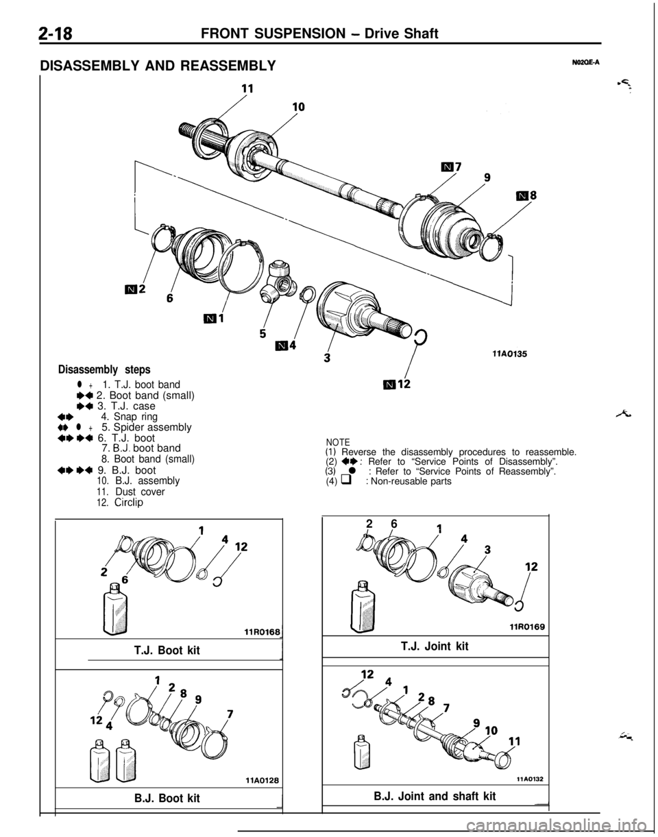
DISASSEMBLY AND REASSEMBLY
NOZOE-A
Disassembly steps
l +1. T.J. boot band
W 2. Boot band (small)e4 3. T.J. case
4*4. Snap ring
4I) l +5. Spider assembly4ee4 6. T.J. boot
7. B.J. boot band
8. Boot band (small)
4ee4 9. B.J. boot10.B.J. assembly
11.Dust cover
12.Circlip
T.J. Boot kitllR0166
llA0128
B.J. Boot kitllAOf35
NOTE(I) Reverse the disassembly procedures to reassemble.
(2) 4+ : Refer to “Service Points of Disassembly”.(3) l : Refer to “Service Points of Reassembly”.
(4) q : Non-reusable parts
2 6
1
llR0169
T.J. Joint kit
-IB.J. Joint and shaft kit
Page 67 of 1216
FRONT SUSPENSION - Drive Shaft249'
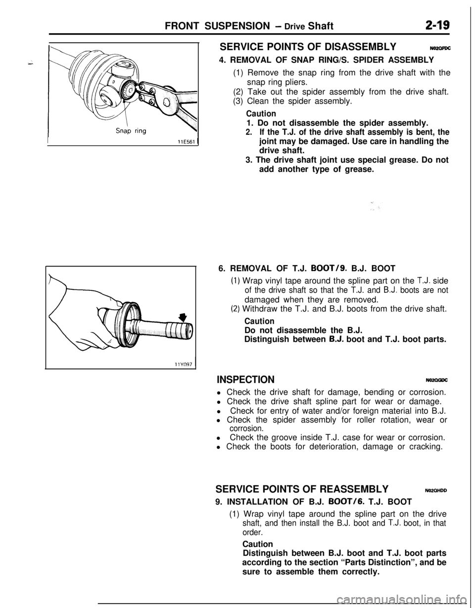
IllE561 ISERVICE POINTS OF DISASSEMBLY
NO2ClFDC4. REMOVAL OF SNAP RING/S. SPIDER ASSEMBLY
(1) Remove the snap ring from the drive shaft with the
snap ring pliers.
(2) Take out the spider assembly from the drive shaft.
(3) Clean the spider assembly.
Caution1. Do not disassemble the spider assembly.
2.If the T.J. of the drive shaft assembly is bent, thejoint may be damaged. Use care in handling the
drive shaft.
3. The drive shaft joint use special grease. Do not
add another type of grease.
6. REMOVAL OF T.J. BOOT/g. B.J. BOOT
(1
(2
) Wrap vinyl tape around the spline part on the T.J. side
of the drive shaft so that the T.J. and B.J. boots are notdamaged when they are removed.
‘) Withdraw the T.J. and B.J. boots from the drive shaft.
CautionDo not disassemble the B.J.
Distinguish between
B.J. boot and T.J. boot parts.
INSPECTIONNO2QGDCl Check the drive shaft for damage, bending or corrosion.
l Check the drive shaft spline part for wear or damage.
lCheck for entry of water and/or foreign material into B.J.
l Check the spider assembly for roller rotation, wear or
corrosion.lCheck the groove inside T.J. case for wear or corrosion.
l Check the boots for deterioration, damage or cracking.
SERVICE POINTS OF REASSEMBLY
NMOHDD9. INSTALLATION OF B.J.
BOOT/6. T.J. BOOT
(1) Wrap vinyl tape around the spline part on the drive
shaft, and then install the B.J. boot and T.J. boot, in that
order.Caution
Distinguish between B.J. boot and T.J. boot parts
according to the section “Parts Distinction”, and be
sure to assemble them correctly.