length MITSUBISHI ECLIPSE 1991 Service Manual
[x] Cancel search | Manufacturer: MITSUBISHI, Model Year: 1991, Model line: ECLIPSE, Model: MITSUBISHI ECLIPSE 1991Pages: 1216, PDF Size: 67.42 MB
Page 18 of 1216
18INTRODUCTION AND MASTER TROUBLESHOOTING - Precautions b&ire Service
DOING SERVICE WORK IN GROUPS OF VO’bRMORE TECHNICIANS
.-I-7.IIf the service work is to be done by two or more technicians
working together, extra caution must be taken.
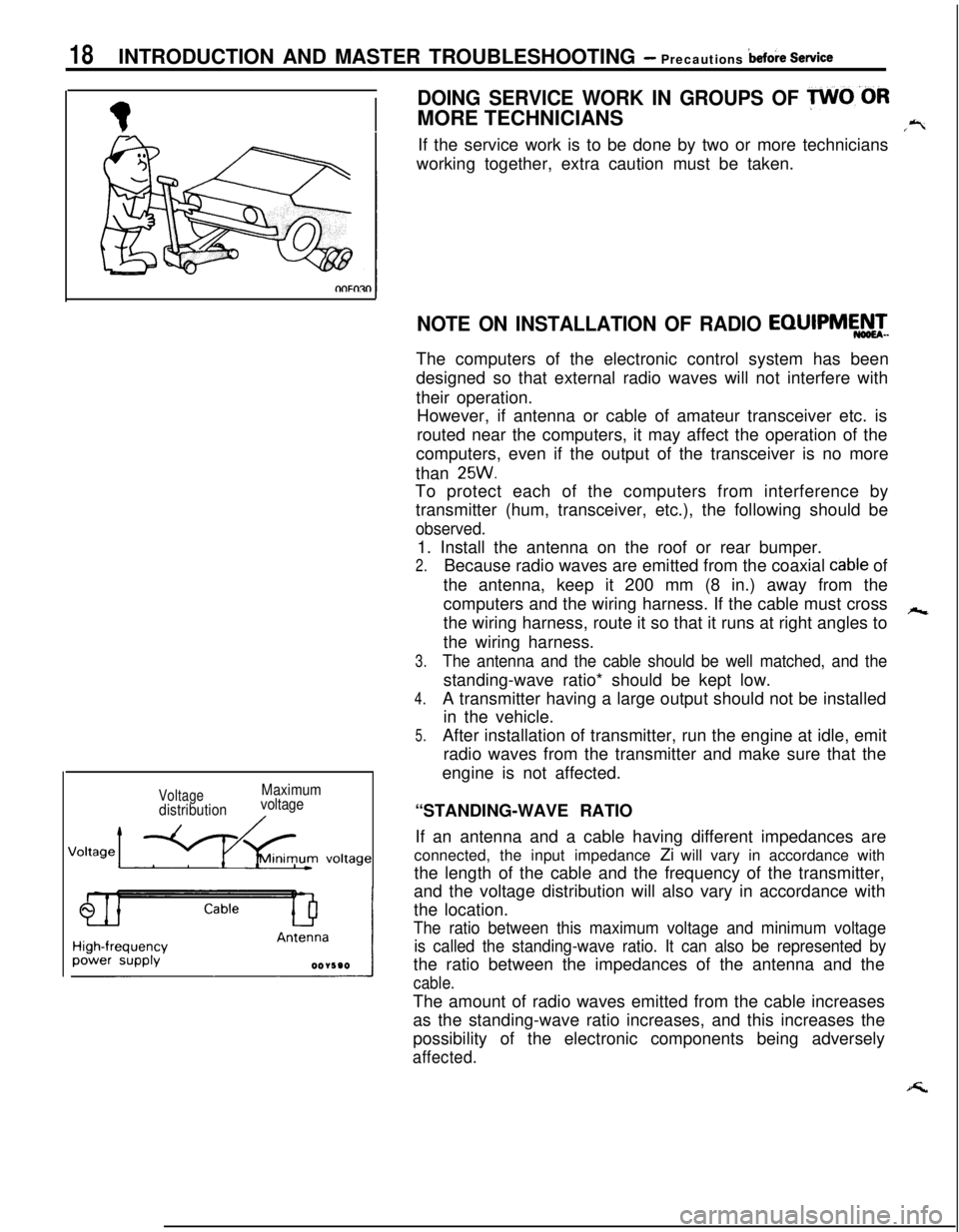
VoltagedistributionMaximum
voltage
NOTE ON INSTALLATION OF RADIO EQIJIPMEATeThe computers of the electronic control system has been
designed so that external radio waves will not interfere with
their operation.
However, if antenna or cable of amateur transceiver etc. is
routed near the computers, it may affect the operation of the
computers, even if the output of the transceiver is no more
than
25W.To protect each of the computers from interference by
transmitter (hum, transceiver, etc.), the following should be
observed.1. Install the antenna on the roof or rear bumper.
2.Because radio waves are emitted from the coaxial cable of
the antenna, keep it 200 mm (8 in.) away from the
computers and the wiring harness. If the cable must cross
hthe wiring harness, route it so that it runs at right angles to
the wiring harness.
3.The antenna and the cable should be well matched, and thestanding-wave ratio* should be kept low.
4.A transmitter having a large output should not be installed
in the vehicle.
5.After installation of transmitter, run the engine at idle, emit
radio waves from the transmitter and make sure that the
engine is not affected.
“STANDING-WAVE RATIO
If an antenna and a cable having different impedances are
connected, the input impedance Zi will vary in accordance with
the length of the cable and the frequency of the transmitter,
and the voltage distribution will also vary in accordance with
the location.
The ratio between this maximum voltage and minimum voltage
is called the standing-wave ratio. It can also be represented bythe ratio between the impedances of the antenna and the
cable.The amount of radio waves emitted from the cable increases
as the standing-wave ratio increases, and this increases the
possibility of the electronic components being adversely
affected.
Page 25 of 1216
INTRODUCTION AND MASTER TROUBLESHOOTING - :;k%ii::& and25
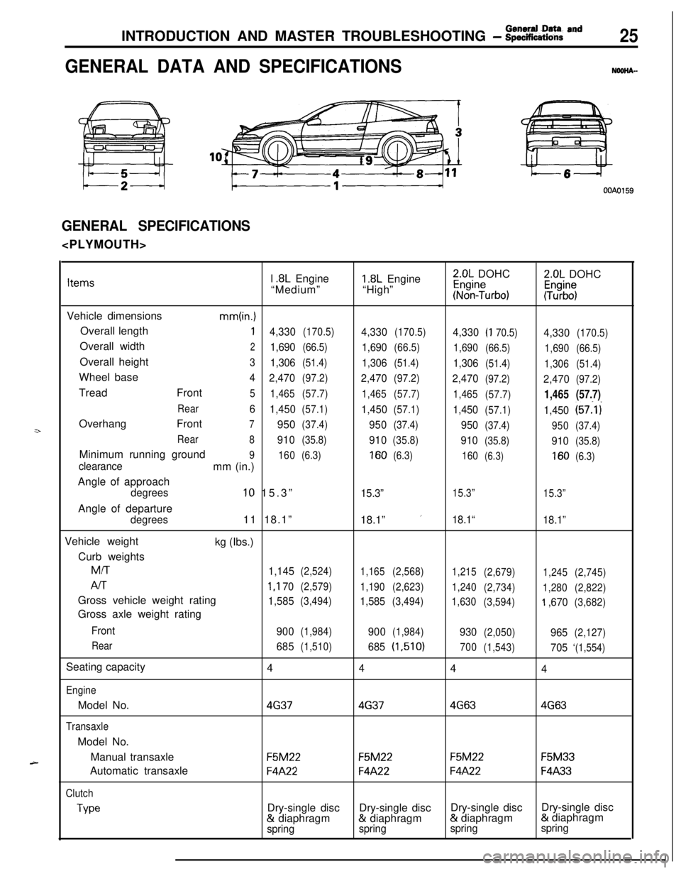
GENERAL DATA AND SPECIFICATIONSNOOHA-
OOAOl59
GENERAL SPECIFICATIONS
z-
A-l
.8L Engine1.8L Engine2.0L DOHC2.0L DOHCItems“Medium”“High”~%n?urbo):Tz%$
Vehicle dimensions
mm(in.)Overall length
14,330(170.5)4,330(170.5)4,330(I 70.5)4,330(170.5)Overall width
21,690(66.5)1,690(66.5)
1,690
(66.5)
1,690(66.5)Overall height
31,306(51.4)1,306(51.4)1,306(51.4)
1,306(51.4)Wheel base
4
2,470(97.2)2,470(97.2)2,470(97.2)2,470(97.2)Tread Front
5
1,465(57.7)
1,465(57.7)
1,465
(57.7)1,465(57.7)
Rear6
1,450(57.1)1,450(57.1)1,450(57.1)1,450(57:l i
Overhang Front
7950(37.4)950(37.4)950(37.4)
950(37.4)
Rear
8
910(35.8)910(35.8)910(35.8)910(35.8)Minimum running ground
9
160(6.3)160(6.3)
160(6.3)160(6.3)clearancemm (in.)
Angle of approach
degrees10 15.3”15.3”15.3”
15.3”Angle of departure
degrees11 18.1”
18.1” ’18.1“
18.1”Vehicle weight
kg (Ibs.)
Curb weights
M/T
1,145(2,524)
1,165(2,568)
1,215
(2,679)
1,245(2,745)
AIT1 ,I 70(2,579)
1,190(2,623)
1,240
(2,734)
1,280(2,822)Gross vehicle weight rating
1,585(3,494)1,585(3,494)
1,630
(3,594)‘I ,670(3,682)Gross axle weight rating
Front
900(1,984)900(1,984)930(2,050)965(2,127)
Rear
685(1,510)685(1,510)
700
(1,543)705‘(1,554)Seating capacity
4
444
EngineModel No.
4G3746374G634G63
TransaxleModel No.
Manual transaxle
F5M22F5M22F5M22F5M33Automatic transaxle
F4A22F4A22F4A22F4A33
Clutch
TypeDry-single discDry-single discDry-single discDry-single disc& diaphragm& diaphragm& diaphragm& diaphragm
springspringspringspring
Page 26 of 1216
26INTRODUCTION AND MASTER TROUBLESHOOTING - :;:%:a=and
Items
Chassis
TireFront suspension
TypeRear suspension
We
Brake
Type
SteeringGear typeFront
RearGear ratio
Fuel tank
Capacityliters (gals.)
1.8L Engine
“Medium”Pl85/70R14
PI 85/70Rl4
Independent
strut
Independentstrut
3l\Fk Torsion&k-k Torsion
Disc
DiscDisc
Disc
Rack and
pinion
03
Rack and
pinion
cn60 (16)
60
(16)
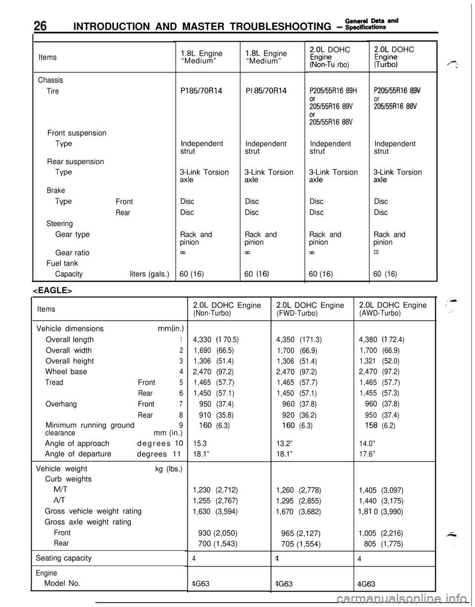
ItemsVehicle dimensions
mm(in.)Overall length
1Overall width
2Overall height
3Wheel base
4
TreadFront5
Rear6
OverhangFront7
Rear8Minimum running ground
9
clearancemm (in.)
Angle of approachdegrees
10Angle of departure
degrees 11
Vehicle weight
kg (Ibs.)Curb weightsMiT
Al-rGross vehicle weight rating
Gross axle weight rating
Front
RearSeating capacity
EngineModel No.
1.8L Engine
“Medium”2.0L DOHC
Kr%n?u rbo)
P205/55Rl6 89H
;;5/55R16 89V%55R16
88V
Independentstrut
zx;;k Torsion
Disc
Disc
Rack and
pinion
co60 (16)
2.0L DOHC
#b”;
P205/55Rl6 89
or
205155R16 88V
Independentstrut
3Lnk Torsion
Disc
Disc
Rack and
pinion
co
60 (16)
2.0L DOHC Engine(Non-Turbo)
4,330(I 70.5)
1,690(66.5)
1,306(51.4)
2,470(97.2)
1,465(57.7)
1,450(57.1)
950(37.4)
910(35.8)
160(6.3)
15.3
18.1”
1,230 (2,712)
1,255 (2,767)
1,630 (3,594)930 (2,050)
700 (1,543)
4
4G63
2.0L DOHC Engine
(FWD-Turbo)
4,350(171.3)
1,700(66.9)
1,306(51.4)
2,470(97.2)
1,465(57.7)
1,450(57.1)
960(37.8)
920(36.2)
160(6.3)
13.2”
18.1”
1,260 (2,778)
1,295 (2,855)
1,670 (3,682)965 (2,127)
705 (1,554)
1
4G63
2.0L DOHC Engine
(AWD-Turbo)
4,380(I 72.4)
1,700(66.9)
1,321(52.0)
2,470(97.2)
1,465(57.7)
1,455(57.3)
960(37.8)
950(37.4)
158(6.2)
14.0”
17.6”
1,405 (3,097)
1,440 (3,175)
I,81 0 (3,990)
1,005 (2,216)
805 (1,775)
4
4G63
Page 36 of 1216
o-2LUBRICATION AND MAINTENANCE - General Information
GENERAL INFORMATIONNGQPA--Maintenance and lubrication service recommenda-
tions have been compiled to provide maximum
protection for the vehicle owner’s investment
against all reasonable types of driving conditions.
Since these conditions vary with the individual
vehicle owner’s driving habits, the area in which the
vehicle is operated and the type of driving to which
the vehicle is subjected, it is necessary to prescribe
lubrication and maintenance service on a time
frequency as well as mileage interval basis.
Oils, lubricants and greases are classified and
graded according to standards recommended by theSociety of Automotive Engineers (SAE), the Amer-
ican Petroleum Institute (API) and the National
Lubricating Grease Institute
(NLGI).MAINTENANCE SCHEDULES
Information for service maintenance is provided
under “SCHEDULED MAINTENANCE TABLE”.
Three schedules are provided; one for “Required
Maintenance”, one for “General Maintenance” and
one for “Severe Usage Service”.
Item numbers in the “SCHEDULED MAINTE-
NANCE TABLE” correspond to the item numbers in
the “MAINTENANCE SERVICE” section.
SEVERE SERVICEVehicles operating under severe service conditions
will require more frequent service.
Component service information is included in
appropriate units for vehicles operating under one ormore of the following conditions:
1.Trailer towing or police, taxi, or commercial type
operation2. Operation of Vehicle
(1) Short-trip operation at freezing temperature
(engine not thoroughly warmed up)
(2) More than 50% operation in heavy city
traffic during hot weather above
32°C (90°F)(3) Extensive idling
(4) Driving in sandy areas
(5) Driving in salty areas
(6) Driving in dusty conditions
ENGINE OIL
The SAE grade number indicates the viscosity of
engine oils, for example, SAE 30, which is a single
grade oil. Engine oils are also identified by a dual
number, for example, SAE
lOW-30, which indicates
a multigrade oil.
The API classification system defines oil perform-
ance in terms of engine usage. Only engine oil
designed “For Service SG” or “For Service
SGKD”,when available, should be used. These oils contain
sufficient chemical additives to provide maximum
engine protection. Both the SAE grade and the API
designation can be found on the container.Caution
Test results submitted to EPA have shown thatlaboratory animals develop skin cancer after
prolonged contact with used engine oil. Accor-
dingly, the potential exists for humans
to de-
velop a number of skin disorders, including
cancer, from such exposure to used engine oil.
Care should be’ taken, therefore, when changingengine oil, to minimize the amount and length of
exposure time to used engine
pi! on your skin.
Protective clothing and gloves, that cannot be
penetrated by oil, should be worn. The skin
should be thoroughly washed with soap and
water, or use waterless hand cleaner, to removeany used engine oil. Do not use gasoline,
thinners, or solvents.
GEAR LUBRICANTSThe SAE grade number also indicates the viscosity
of Multi-Purpose Gear Lubricants.
The API classfication system defines gear lubricants
in terms of usage. Typically gear lubricants conform-ing to API
GL-4 or GL-5 with a viscosity of SAE
75W-85W are recommended for manual transaxle.
LUBRICANTS
- GREASES
Semi-solid lubricants, bear the NLGI designation andare further classified as grades 0, 1, 2, 3 etc.
Whenever “Chassis Lubricant” is specified, Multi-
Purpose Grease,
NLGI grade 2 should be used.
MOPAR Multi-Mileage Lubricant, P&t Number
2525035 or equivalent, meets these requirement
and is recommended.
FUEL USAGE STATEMENT
Use gasolines having a minimum anti-knock index
(Octane Value) of 87,
(R + M)/2. This designation is
comparable to a Research Octane Number of 91.
Unleaded gasolines only must be used in vehicles
equipped with catalyst emission control systems.
All vehicles, so equipped, have labels located on the
instrument panel and on the back of fuel filler lid that
state, “UNLEADED GASOLINE ONLY”. These vehi-
cles also have fuel filler tubes especially designed toaccept the smaller diameter unleaded gasoline
dispensing nozzles only.
MATERIALS ADDED
TO FUELIndiscriminate use of fuel system cleanng agents
should be avoided. Many of these materials in-
tended for gum and varnish removal may contain
highly active solvents or similar ingredients that can
be harmful to gasket and diaphragm materials usedin fuel system component parts.
Page 47 of 1216
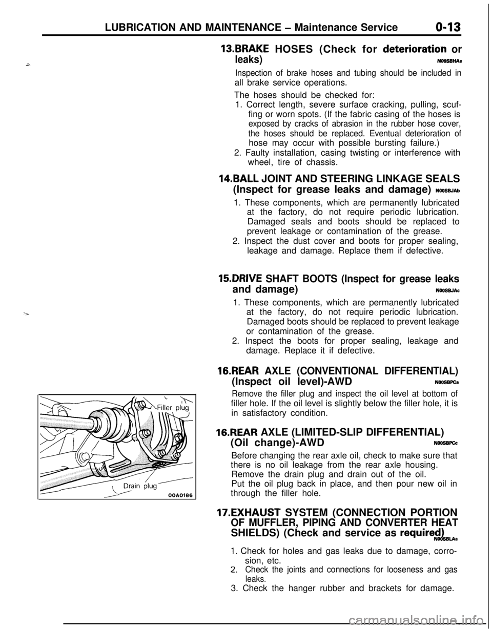
LUBRICATION AND MAINTENANCE - Maintenance Serviceo-13
OOAOlB6
13.BRAKE HOSES (Check for deteriorati.on or
leaks)NwBBnAs
Inspection of brake hoses and tubing should be included inall brake service operations.
The hoses should be checked for:
1. Correct length, severe surface cracking, pulling, scuf-
fing or worn spots. (If the fabric casing of the hoses is
exposed by cracks of abrasion in the rubber hose cover,
the hoses should be replaced. Eventual deterioration ofhose may occur with possible bursting failure.)
2. Faulty installation, casing twisting or interference with
wheel, tire of chassis.
14.BALL JOINT AND STEERING LINKAGE SEALS
(Inspect for grease leaks and damage)
NWSBJAb1. These components, which are permanently lubricated
at the factory, do not require periodic lubrication.
Damaged seals and boots should be replaced to
prevent leakage or contamination of the grease.
2. Inspect the dust cover and boots for proper sealing,
leakage and damage. Replace them if defective.
15.DRIVE SHAFT BOOTS (Inspect for grease leaksand damage)
NWSBJAc1. These components, which are permanently lubricated
at the factory, do not require periodic lubrication.
Damaged boots should be replaced to prevent leakage
or contamination of the grease.
2. Inspect the boots for proper sealing, leakage and
damage. Replace it if defective.
16.REAR AXLE (CONVENTIONAL DIFFERENTIAL)(Inspect oil level)-AWD
NWSBFCa
Remove the filler plug and inspect the oil level at bottom offiller hole. If the oil level is slightly below the filler hole, it is
in satisfactory condition.
16.REAR AXLE (LIMITED-SLIP DIFFERENTIAL)
(Oil change)-AWD
N66SBFCcBefore changing the rear axle oil, check to make sure that
there is no oil leakage from the rear axle housing.
Remove the drain plug and drain out of the oil.
Put the oil plug back in place, and then pour new oil in
through the filler hole.
17.EXHAUST SYSTEM (CONNECTION PORTION
OF MUFFLER, PIPING AND CONVERTER HEATSHIELDS) (Check and service as
require$dBu.
1. Check for holes and gas leaks due to damage, corro-
sion, etc.
2.Check the joints and connections for looseness and gas
leaks.3. Check the hanger rubber and brackets for damage.
Page 50 of 1216
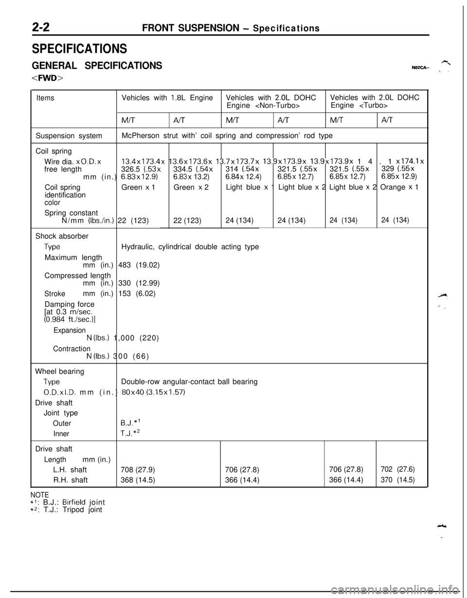
2-2FRONT SUSPENSION - Specifications
SPECIFICATIONS
GENERAL SPECIFICATIONSNOZCA-
ItemsVehicles with 1.8L EngineVehicles with 2.0L DOHCVehicles with 2.0L DOHC
Engine
MM/TAITMITNTSuspension systemMcPherson strut with’ coil spring and compression’ rod type
Coil spring
Wire dia.
x0.D. x13.4x173.4x 13.6x173.6x 13.7x173.7x 13.9x173.9x 13.9x173.9x 14.1 x174.1xfree length326.5 (.53x334.5 (.54x314 (.54x321.5 (.55x321.5 (.55x329 (.55x
mm (in.) 6.83x12.9)6.83x
13.2)6.84x 12.4)6.85x 12.7)6.85x 12.7)6.85x 12.9)Coil springGreen
x 1Green x 2Light blue x 1 Light blue x 2 Light blue x 2 Orange x 1
identification
colorSpring constant
N/mm
(IbsAn.) 22 (123)22 (123)24 (134)24 (134)24 (134)24 (134)Shock absorber
TypeHydraulic, cylindrical double acting type
Maximum length
mm (in.) 483 (19.02)
Compressed length
mm (in.) 330 (12.99)
Strokemm (in.) 153 (6.02)
Damping force
[at 0.3
m/set.
(0.984 ft./sec.)l
Expansion
N (Ibs.) 1,000 (220)
ContractionN (Ibs.) 300 (66)
Wheel bearing
TypeDouble-row angular-contact ball bearing
0.D.xl.D. mm (in.) 80x40 (3.15x1.57)
Drive shaft
Joint type
OuterB.J.“l
InnerT.J.“’Drive shaft
Lengthmm (in.)
L.H. shaft708 (27.9)706 (27.8)
R.H. shaft368 (14.5)366 (14.4)
NOTE*1: B.J.: Birfield joint*2: T.J.: Tripod joint706 (27.8)
702 (27.6)366 (14.4)
370 (14.5)
Page 51 of 1216
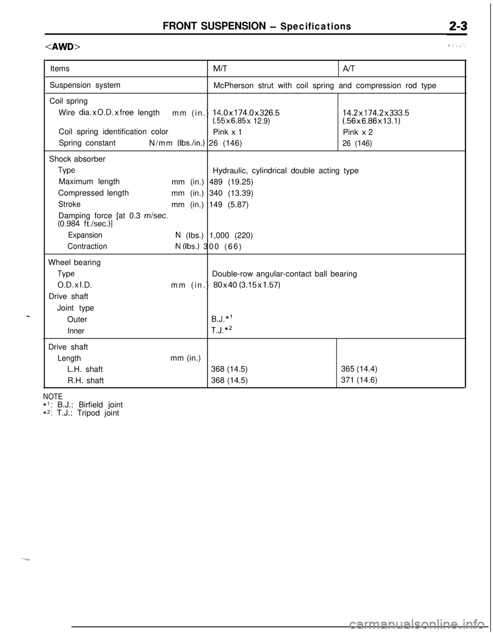
FRONT SUSPENSION - SpecificationsItemsMiT
Al-rSuspension system
McPherson strut with coil spring and compression rod type
Coil spring
Wire
dia.xO.D.xfree length
mm (in.) 14.0x174.0x326.514.2x174.2x333.5(.55x6.85x 12.9)(.56x6.86x13.1)
Coil spring identification color
Pink
x 1
Pink x 2
Spring constant
N/mm
(Ibs./in.) 26 (146)26 (146)Shock absorber
TypeHydraulic, cylindrical double acting type
Maximum length
mm (in.) 489 (19.25)
Compressed length
mm (in.) 340 (13.39)
Strokemm (in.) 149 (5.87)
Damping force [at 0.3 m/set.
(0.984 ft./set.)]
ExpansionN (Ibs.) 1,000 (220)
ContractionN (Ibs.) 300 (66)
Wheel bearing
TypeDouble-row angular-contact ball bearing
0.D.xl.D.mm (in.) 80x40 (3.15x1.57)
Drive shaft
Joint type
Outer
B.J.“’
InnerT.J.“’Drive shaft
Lengthmm (in.)
L.H. shaft368 (14.5)365 (14.4)
R.H. shaft368 (14.5)371 (14.6)
NOTE
*I: B.J.: Birfield joint**: T.J.: Tripod joint
Page 52 of 1216
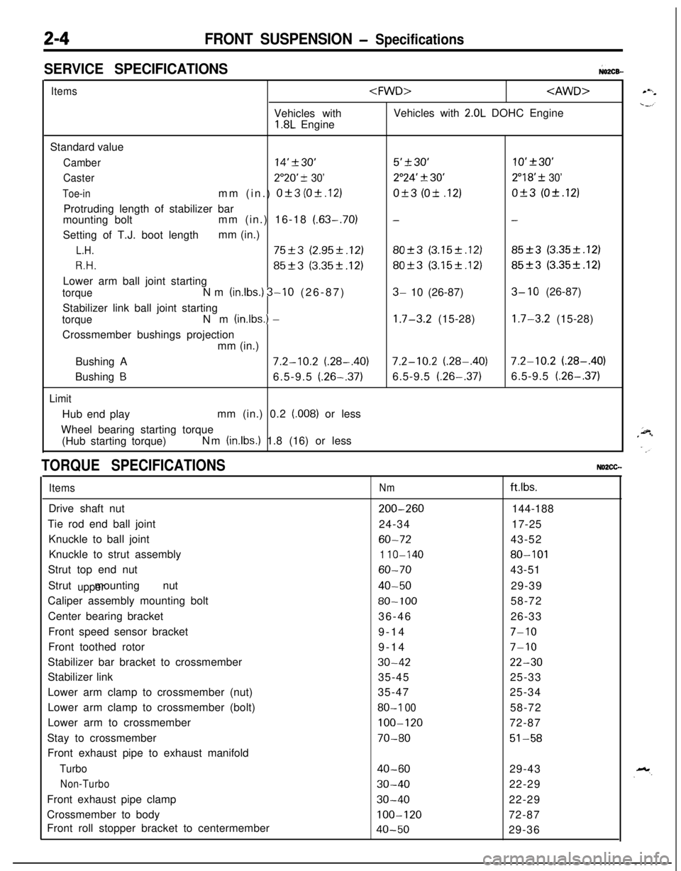
2-4FRONT SUSPENSION - Specifications
SERVICE SPECIFICATIONS;02CB-
ItemsVehicles with
1.8L Engine
2.0L DOHC Engine
Standard value
Camber14’230’5’+30’10’+30’
Caster2”20’ -t 30’2”24’ 3130’2”18’ f 30’
Toe-inmm (in.) Of3 (Ok.12)Of3 (Ok .12)Of3 (Ok.12)
Protruding length of stabilizer bar
mounting boltmm (in.) 16-18
(.63-.70)--Setting of T.J. boot lengthmm (in.)
L.H.75+3 (2.95f.12)80-+3 (3.15f.12)85_+3 (3.35k.12)
R.H.85f3 (3.35k.12)80+3 (3.15k.12)85f3 (3.35f.12)Lower arm ball joint starting
torqueNm (in.lbs.) 3-10 (26-87)3- 10 (26-87)3- 10 (26-87)
Stabilizer link ball joint starting
torqueNm (inlbs.) -1.7-3.2 (15-28)1.7-3.2 (15-28)
Crossmember bushings projection
mm (in.)
Bushing A
7.2-10.2 (.28-.40)7.2-10.2 (.28-.40)7.2-10.2 (.28-.40)
Bushing
B6.5-9.5 (.26-.37)6.5-9.5 (.26-.37)6.5-9.5 (.26-.37)
LimitHub end playmm (in.) 0.2
(.008) or less
Wheel bearing starting torque
(Hub starting torque)Nm
(in.lbs.) 1.8 (16) or less
TORQUE SPECIFICATIONSNO2CG.
ItemsDrive shaft nut
Tie rod end ball joint
Knuckle to ball joint
Knuckle to strut assembly
Strut top end nut
Strut mounting nut
upperCaliper assembly mounting bolt
Center bearing bracket
Front speed sensor bracket
Front toothed rotor
Stabilizer bar bracket to crossmember
Stabilizer link
Lower arm clamp to crossmember (nut)
Lower arm clamp to crossmember (bolt)
Lower arm to crossmember
Stay to crossmember
Front exhaust pipe to exhaust manifold
Turbo
Non-TurboFront exhaust pipe clamp
Crossmember to body
Front roll stopper bracket to centermember
Nmftlbs.
200-260144-188
24-3417-25
60-7243-52
1 IO-14080-101
60-7043-51
40-5029-39
80-10058-72
36-4626-33
9-14
7-109-14
7-10
30-4222-3035-4525-33
35-4725-34
80-I 0058-72
100-12072-87
70-8051-58
40-6029-43
30-4022-29
30-4022-29
100-12072-87
40-5029-36
Page 69 of 1216
FRONT SUSPENSION - Drive Shaft
DRIVE SHAFT
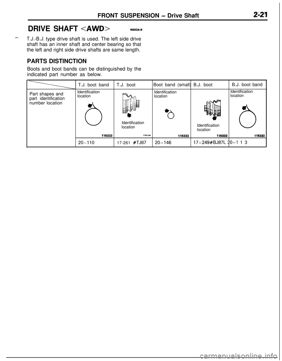
T.J.-B.J. type drive shaft is used. The left side drive
shaft has an inner shaft and center bearing so that
the left and right side drive shafts are same length.
PARTS DISTINCTION
Boots and boot bands can be distinguished by the
indicated part number as below.
Part shapes and
part identification
number location
T.J. boot bandT.J. bootBoot band (small) B.J. bootB.J. boot band
Identification
IdentificationIdentification
location
locationlocation
uIdentification
locationIdentificationlocation6
llK033llRO,SBllK033llK033llKO33
20-I 1017-261 #TJ8720-14617-249#BJ87L 20-I 13
Page 79 of 1216
FRONT SUSPENSION - Strut Assembly
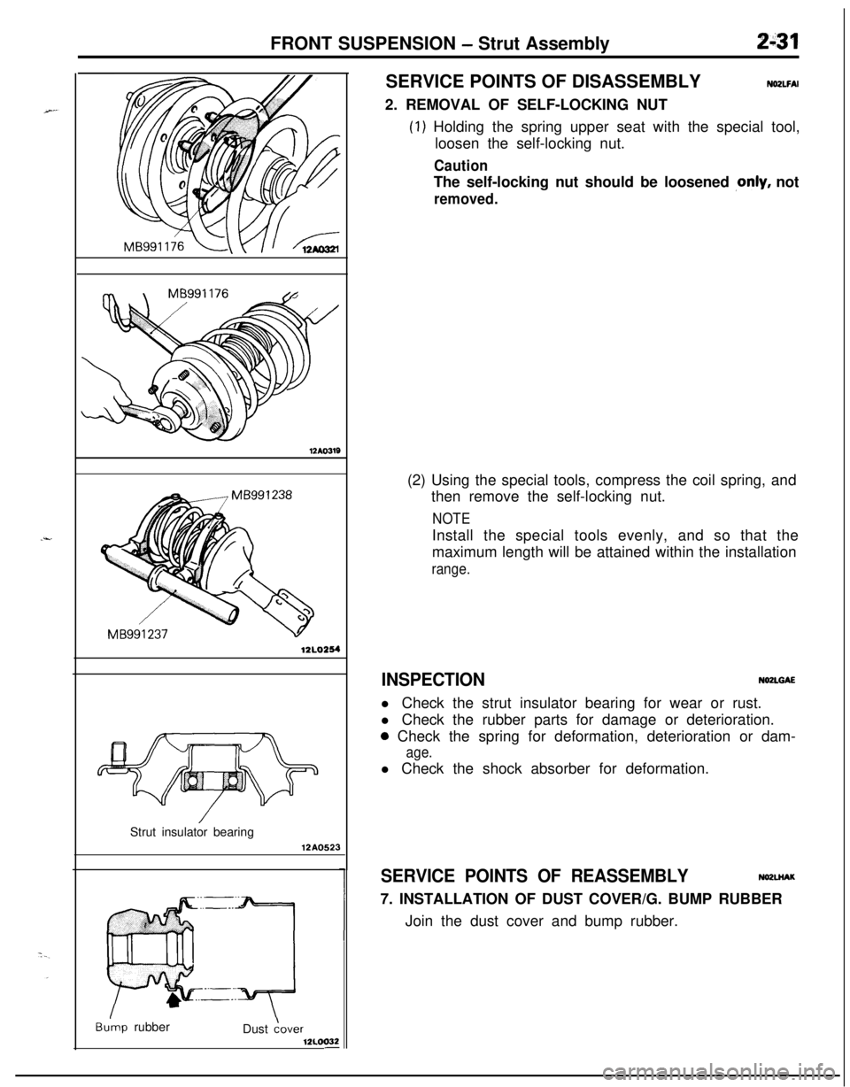
MB991237 -12l.0254
Strut insulator bearing12A0523
Bu’mp rubber
Dust Gover12LOO32-SERVICE POINTS OF DISASSEMBLY
NO2LFAI2. REMOVAL OF SELF-LOCKING NUT
(1) Holding the spring upper seat with the special tool,
loosen the self-locking nut.
CautionThe self-locking nut should be loosened
,only, not
removed.(2) Using the special tools, compress the coil spring, and
then remove the self-locking nut.
NOTEInstall the special tools evenly, and so that the
maximum length will be attained within the installation
range.
INSPECTIONNOZLGAEl Check the strut insulator bearing for wear or rust.
l Check the rubber parts for damage or deterioration.
0 Check the spring for deformation, deterioration or dam-
age.l Check the shock absorber for deformation.
SERVICE POINTS OF REASSEMBLYNO2LHAK7. INSTALLATION OF DUST COVER/G. BUMP RUBBER
Join the dust cover and bump rubber.