service MITSUBISHI ECLIPSE 1991 Service Manual
[x] Cancel search | Manufacturer: MITSUBISHI, Model Year: 1991, Model line: ECLIPSE, Model: MITSUBISHI ECLIPSE 1991Pages: 1216, PDF Size: 67.42 MB
Page 1086 of 1216
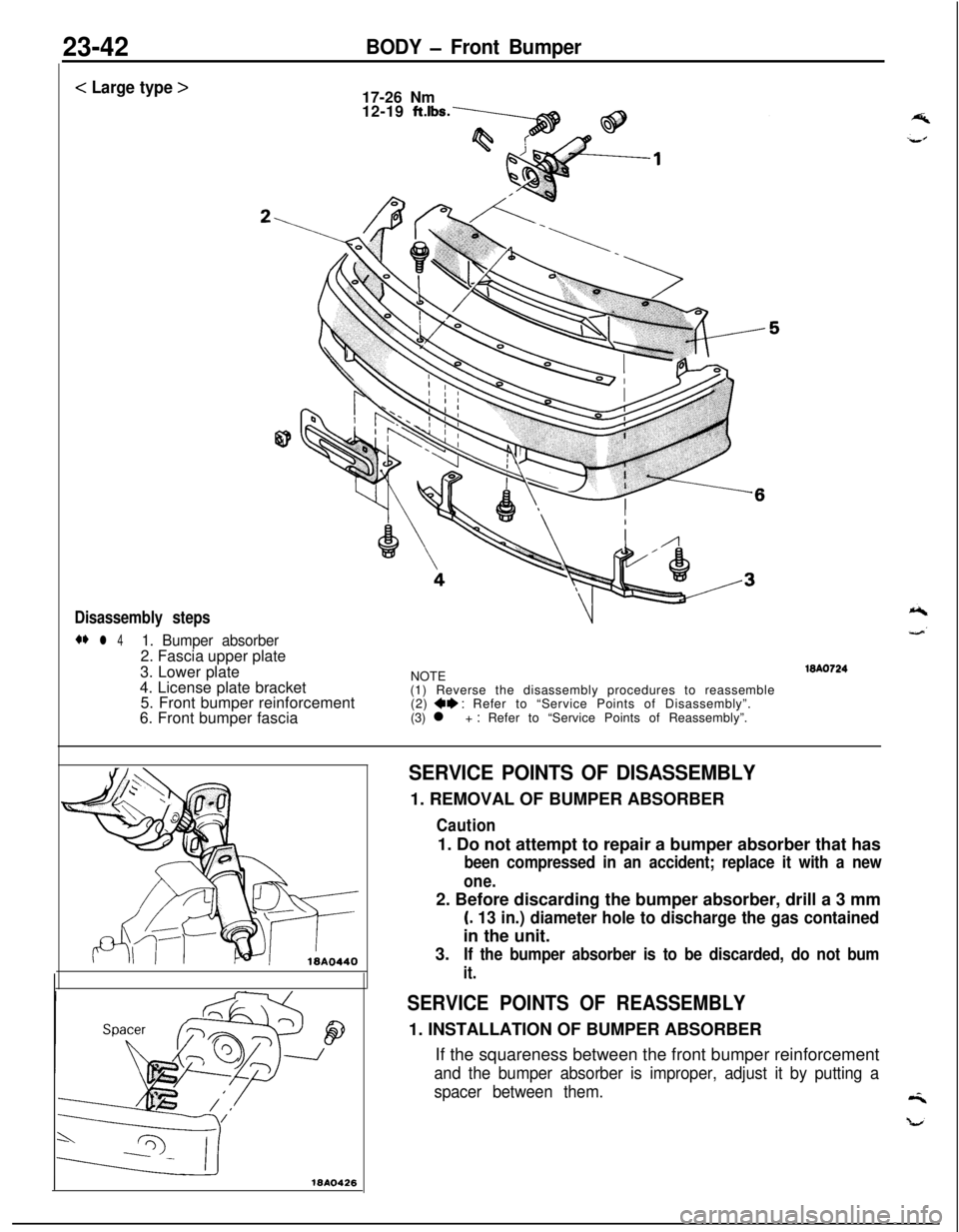
23-42BODY - Front Bumper
< Large type >
17-26 Nm
12-19
ftlbs.
Disassembly steps
** l 41. Bumper absorber2. Fascia upper plate
3. Lower plate
4. License plate bracket
5. Front bumper reinforcement
6. Front bumper fasciaNOTE
(1) Reverse the disassembly procedures to reassemble
(2)
+e : Refer to “Service Points of Disassembly”.
(3) l + : Refer to “Service Points of Reassembly”.WA0724
18410426
SERVICE POINTS OF DISASSEMBLY1. REMOVAL OF BUMPER ABSORBER
Caution1. Do not attempt to repair a bumper absorber that has
been compressed in an accident; replace it with a new
one.2. Before discarding the bumper absorber, drill a 3 mm
(. 13 in.) diameter hole to discharge the gas containedin the unit.
3.
If the bumper absorber is to be discarded, do not bum
it.
SERVICE POINTS OF REASSEMBLY1. INSTALLATION OF BUMPER ABSORBER
If the squareness between the front bumper reinforcement
and the bumper absorber is improper, adjust it by putting a
spacer between them.
Page 1089 of 1216

BODY - Rear Bummer23-45
DISASSEMBLY AND REASSEMBLY<
Normal type >
Disassembly steps1. License plate light
2. Back-up light
3. Rear side marker light
4. License plate light wiring harness
5. Bumper absorber
6. Rear bumper reinforcement
7. License plate bracket
8. Rear bumper fasciaNOTE
(1) Reverse the disassembly procedures to reassemble.(2) +* : Refer to “Service Points of Disassembly”.
SERVICE POINTS OF DISASSEMBLY5. REMOVAL OF BUMPER ABSORBER
Caution1. Do not attempt to repair a bumper absorber that has
been compressed in an accident; replace it with a new
one.2. Before discarding the bumper absorber, drill a 3 mm
(. 13 in.) diameter hole to discharge the gas containedin the unit.
3.
If the bumper absorber is to be discarded, do not burn
it.
Page 1090 of 1216
23-46BODY - Rear Bumper
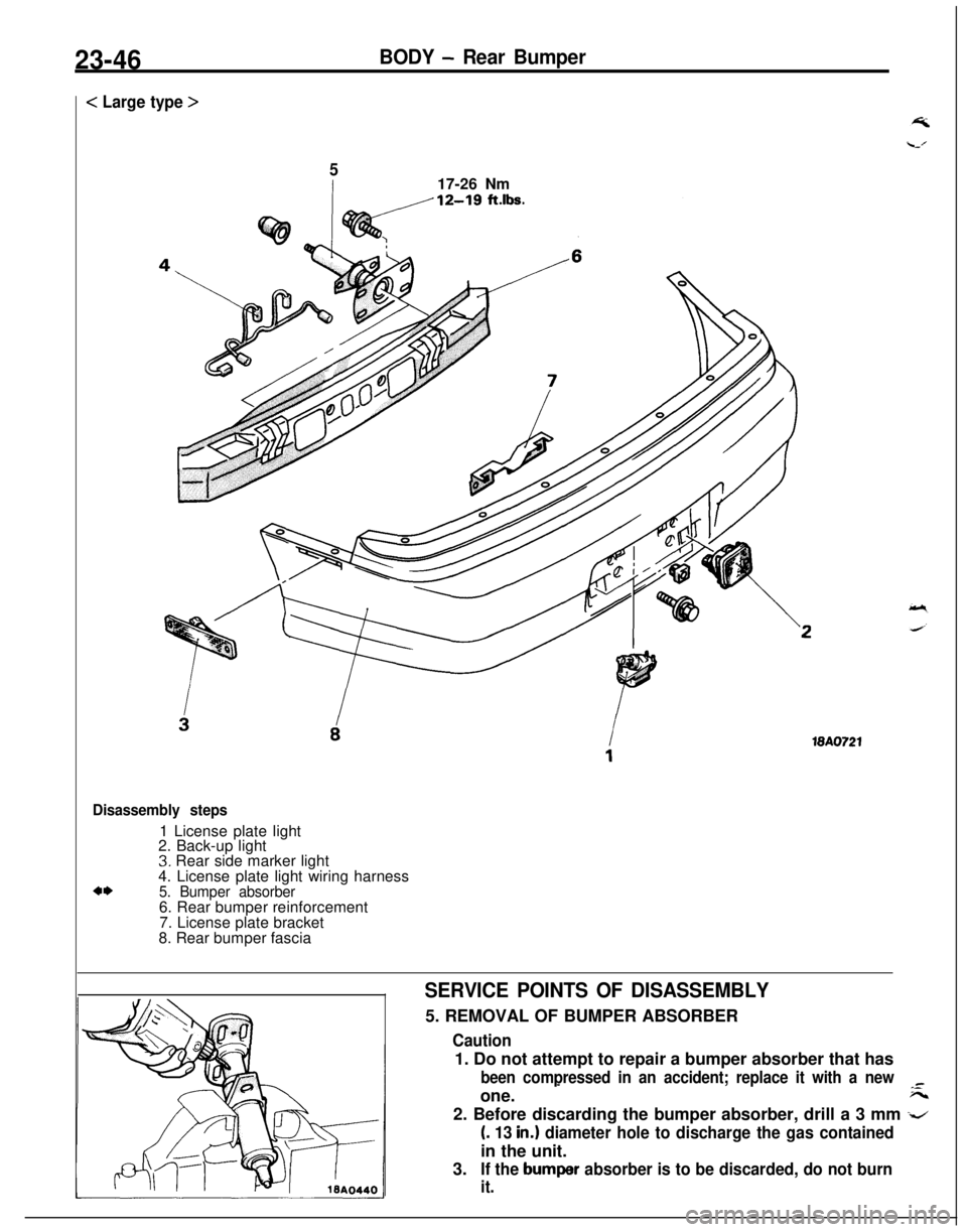
< Large type >
517-26 Nm
18A0721
Disassembly steps1 License plate light
2. Back-up light
3. Rear side marker light
4. License plate light wiring harness
4*5. Bumper absorber6. Rear bumper reinforcement
7. License plate bracket
8. Rear bumper fascia
SERVICE POINTS OF DISASSEMBLY5. REMOVAL OF BUMPER ABSORBER
Caution1. Do not attempt to repair a bumper absorber that has
been compressed in an accident; replace it with a new-one.
-F--2. Before discarding the bumper absorber, drill a 3 mm
-z
(. 13 in.1 diameter hole to discharge the gas containedin the unit.
3.
If the bumper absorber is to be discarded, do not burn
it.
Page 1091 of 1216
BODY - Garnishes2347
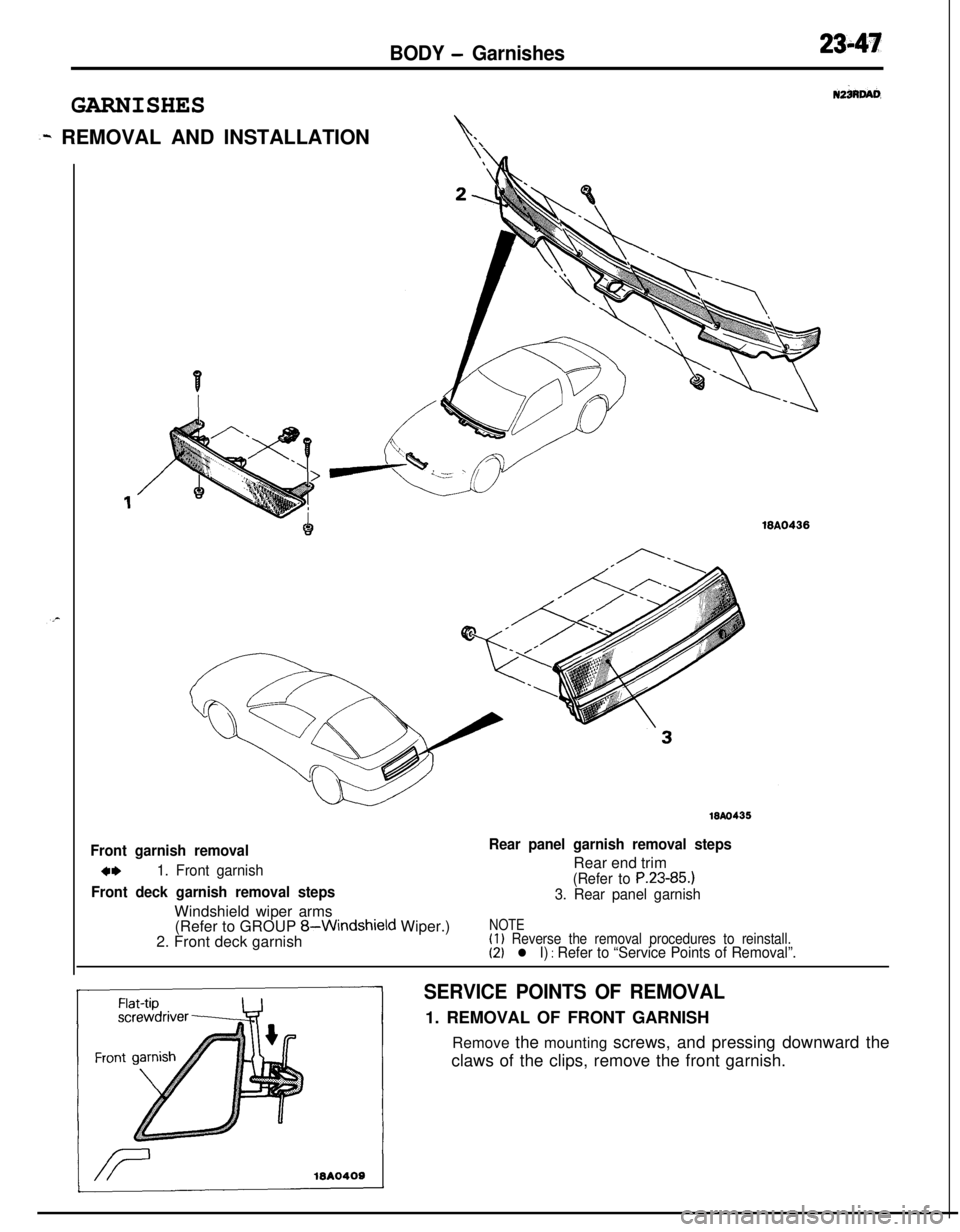
GARNISHES
N2iRW
~w REMOVAL AND INSTALLATIONi‘\
18Ao435
Front garnish removal
4m1. Front garnish
Front deck garnish removal stepsWindshield wiper arms
Rear panel garnish removal stepsRear end trim
(Refer to P.23-85.)
3. Rear panel garnish(Refer to GROUP
8-Windshield Wiper.)
2. Front deck garnishNOTE(1) Reverse the removal procedures to reinstall.(2) l I) : Refer to “Service Points of Removal”.
SERVICE POINTS OF REMOVAL1. REMOVAL OF FRONT GARNISH
Remove the mounting screws, and pressing downward the
claws of the clips, remove the front garnish.
Page 1092 of 1216
23-48
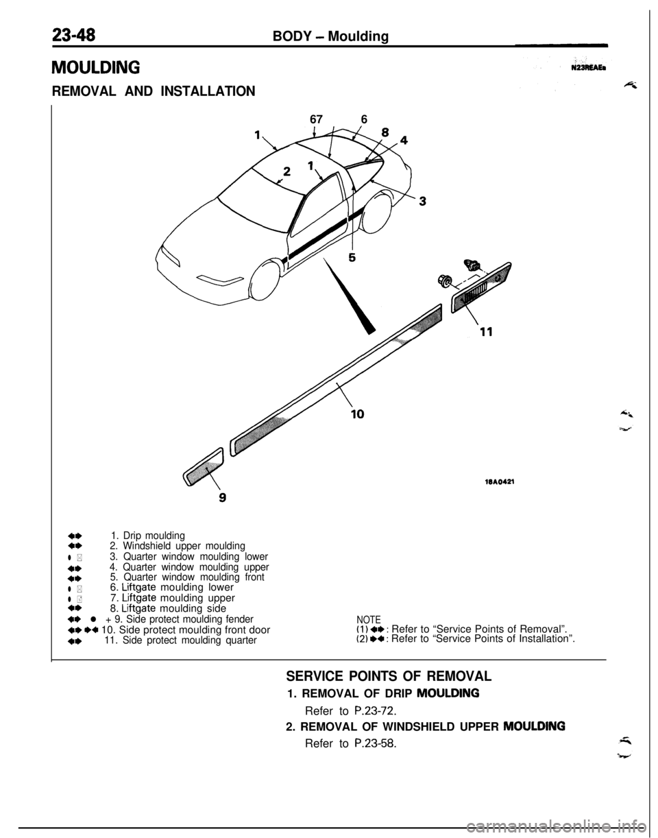
MOULDINGBODY
- Moulding
REMOVAL AND INSTALLATION67 6WA0421
4,1. Drip moulding4,2. Windshield upper moulding
l *3. Quarter window moulding lower
**4. Quarter window moulding upper
4*5. Quarter window moulding front
l *6. Liftgate moulding lower
l +7. Liftgate moulding uppera*8. Liftgate moulding side
+* l + 9. Side protect moulding fender
+e I)+ 10. Side protect moulding front door
4,11. Side protect moulding quarter
NOTE(1) ** : Refer to “Service Points of Removal”.(2) I)+ : Refer to “Service Points of Installation”.
SERVICE POINTS OF REMOVAL1. REMOVAL OF DRIP MOULDING
Refer to
P.23-72.2. REMOVAL OF WINDSHIELD UPPER
MOULDINGRefer to
P.23-58.
Page 1093 of 1216
BODY - Moulding23-493.
REMOVAL OF QUARTER WINDOW MOULDING LOWER/
4. QUARTER WINDOW MOULDING UPPER/B. QUARTERWINDOW MOULDING FRONT
Refer to
P.23-61.6. REMOVAL OF
LIFTGATE MOULDING LOWERI7. LIFT-GATE MOULDING
UPPER/8. LIFTGATE MOULDING
SIDERefer to
P.23-62.
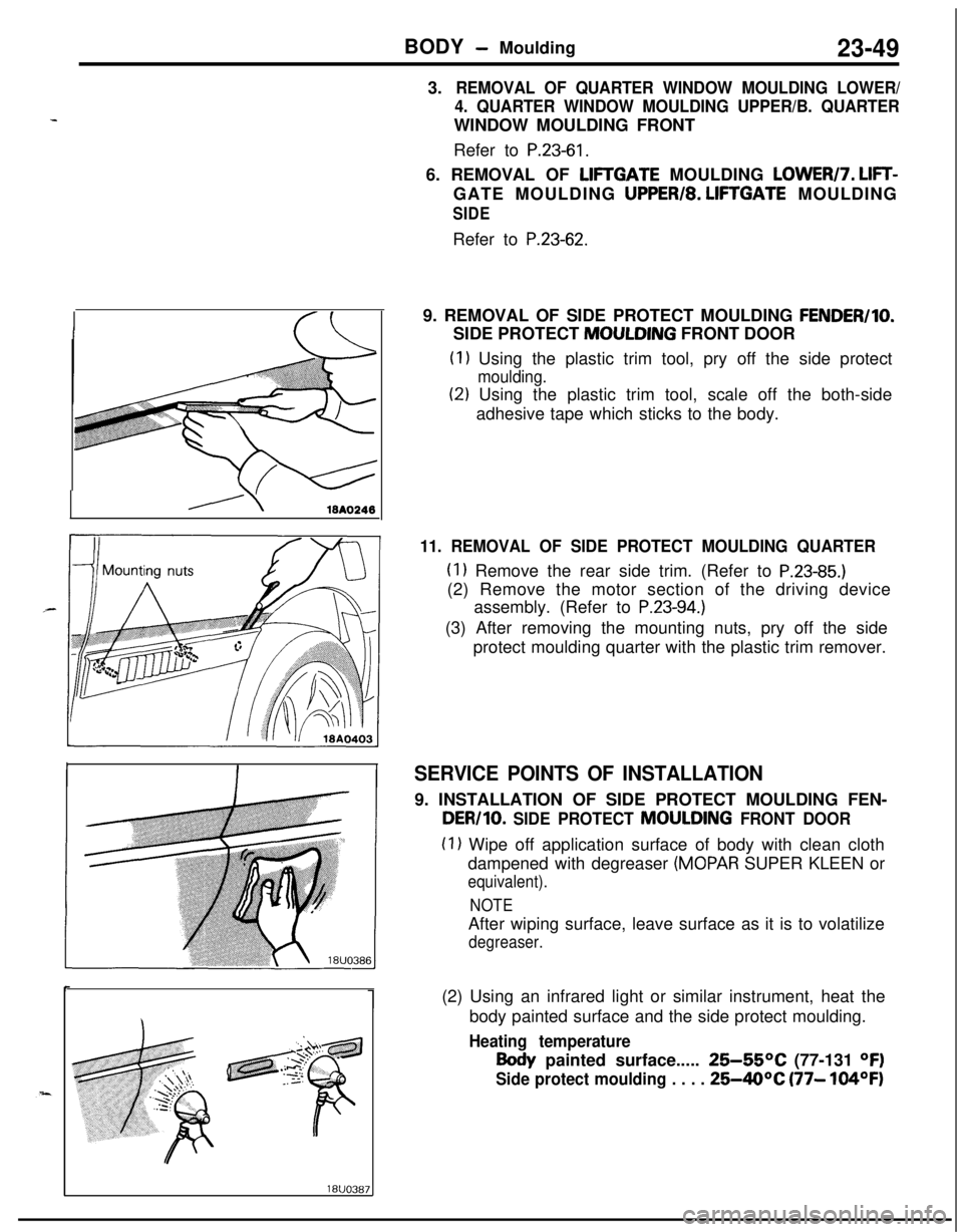
19. REMOVAL OF SIDE PROTECT MOULDING
FENDER/IO.SIDE PROTECT MOULDING FRONT DOOR
(1) Using the plastic trim tool, pry off the side protect
moulding.
(2) Using the plastic trim tool, scale off the both-side
adhesive tape which sticks to the body.
11. REMOVAL OF SIDE PROTECT MOULDING QUARTER
(1) Remove the rear side trim. (Refer to P.23-85.)(2) Remove the motor section of the driving device
assembly. (Refer to
P.23-94.)(3) After removing the mounting nuts, pry off the side
protect moulding quarter with the plastic trim remover.
SERVICE POINTS OF INSTALLATION9. INSTALLATION OF SIDE PROTECT MOULDING FEN-
DER/10. SIDE PROTECT MOULDING FRONT DOOR
(1) Wipe off application surface of body with clean cloth
dampened with degreaser
(MOPAR SUPER KLEEN or
equivalent).
NOTEAfter wiping surface, leave surface as it is to volatilize
degreaser.(2) Using an infrared light or similar instrument, heat the
body painted surface and the side protect moulding.
Heating temperature
Body painted surface..... 25-55OC (77-131 OF)
Side protect moulding . . . . 25-40°C (77- 104OF)
Page 1095 of 1216
BODY - Fender
FENDER
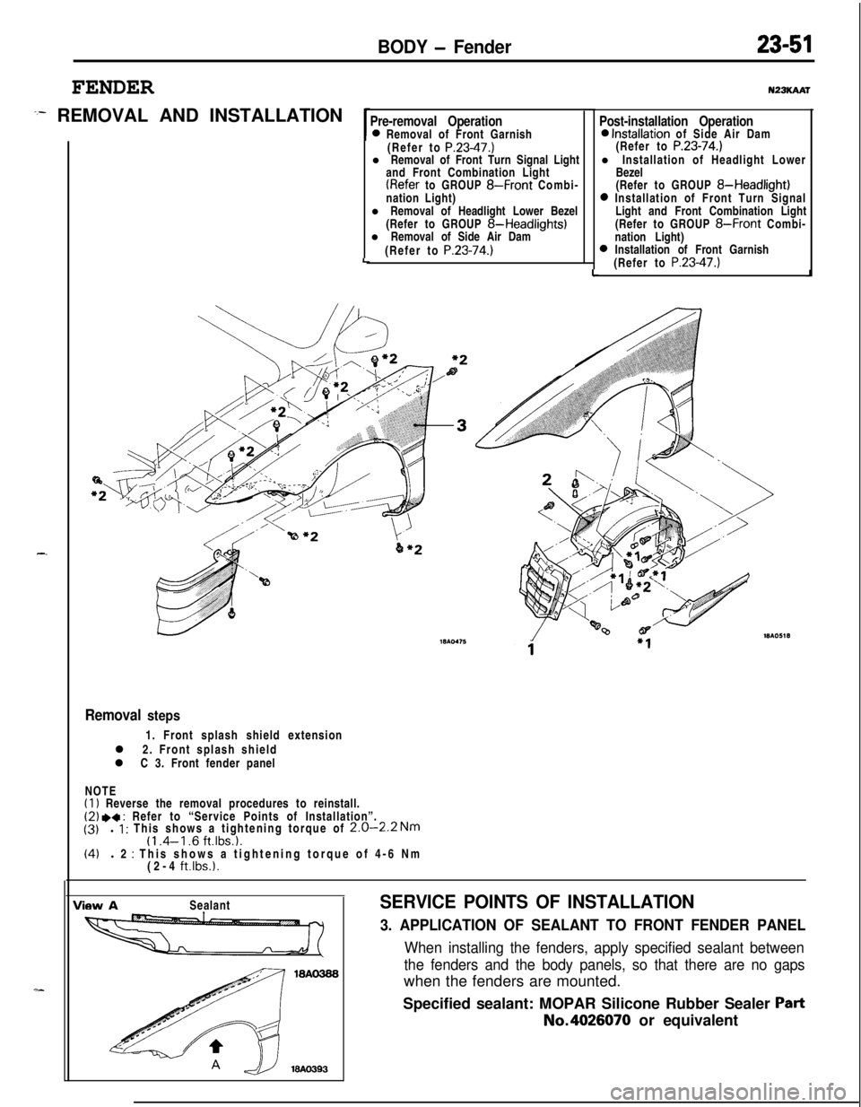
:- REMOVAL AND INSTALLATION
-.
Pre-removal Operation0 Removal of Front Garnish
(Refer to P.23-47.)l Removal of Front Turn Signal Light
and Front Combination Light
(Refer to GROUP 8-Front Combi-
nation Light)
l Removal of Headlight Lower Bezel
(Refer to GROUP
8-Headlights)l Removal of Side Air Dam
(Refer to
P.23-74.)LLu23KAAr
Post-installation Operation0 Installation of Side Air Dam
(Refer to P.23-74.)l Installation of Headlight Lower
Bezel
(Refer to GROUP
8-Headlight)0 Installation of Front Turn Signal
Light and Front Combination Light
(Refer to GROUP
8-Front Combi-
nation Light)
0 Installation of Front Garnish
(Refer to P.23-47.)J
Removal steps1. Front splash shield extension
l 2. Front splash shield
l C 3. Front fender panel
NOTE
(1) Reverse the removal procedures to reinstall.(2) .a : Refer to “Service Points of Installation”.
(3)l 1 : This shows a tightening torque of 2.0-2.2 Nm(1 .4-l .6 ft.lbs.1.(4)l 2 : This shows a tightening torque of 4-6 Nm
(2-4 ft.lbs.1.
View ASealantSERVICE POINTS OF INSTALLATION
3. APPLICATION OF SEALANT TO FRONT FENDER PANEL
When installing the fenders, apply specified sealant between
the fenders and the body panels, so that there are no gapswhen the fenders are mounted.
Specified sealant: MOPAR Silicone Rubber Sealer
PartNo.4026070 or equivalent
Page 1098 of 1216
23-54BODY - Window Glass
WINDOW GLASS
N23LAAB
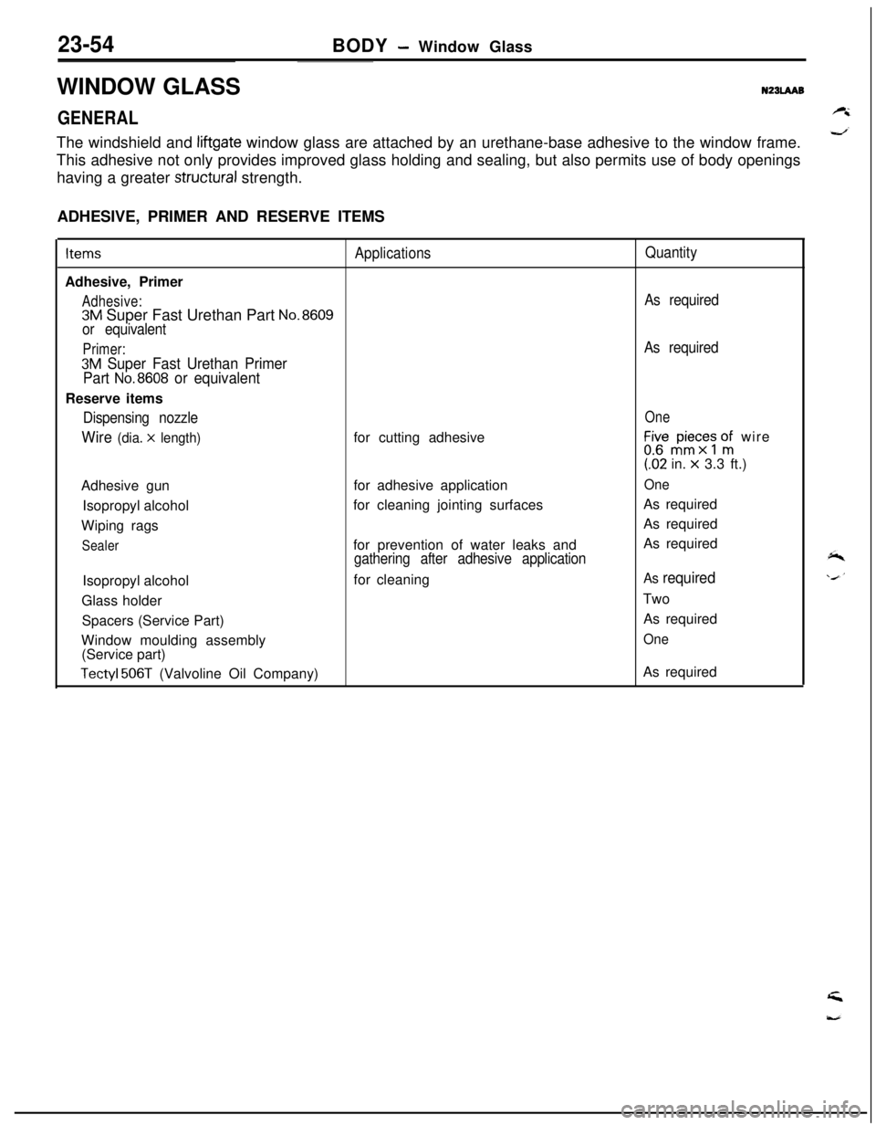
GENERALThe windshield and
liftgate window glass are attached by an urethane-base adhesive to the window frame.
This adhesive not only provides improved glass holding and sealing, but also permits use of body openings
having a greater
structural strength.
ADHESIVE, PRIMER AND RESERVE ITEMSItems
ApplicationsQuantityAdhesive, Primer
Adhesive:As required
3M Super Fast Urethan Part No.8609
or equivalent
Primer:As required
3M Super Fast Urethan Primer
Part
No.8608 or equivalentReserve items
Dispensing nozzleOne
Wire (dia. x length)for cutting adhesiveLir,“$c;s onfi wire(62 in.
x 3.3 ft.)
Adhesive gunfor adhesive application
OneIsopropyl alcoholfor cleaning jointing surfacesAs required
Wiping ragsAs required
Sealerfor prevention of water leaks andAs requiredgathering after adhesive applicationIsopropyl alcoholfor cleaning
As requiredGlass holderTwo
Spacers (Service Part)As required
Window moulding assembly
One(Service part)
Tectyl 506T (Valvoline Oil Company)As required
Page 1102 of 1216
23-58BODY - Windshield
WINDSHIELD
REMOVAL AND INSTALLATION
ISA0466
Pre-removal Operation0 Removal of Hood
(Refer to P.23-34.)0 Removal of Wiper Arm
(Refer to GROUP &WindshieldWiper)
l Removal of Front Deck Garnish
(Refer to
P.23-47.)0 Removal of Front Headlining Trim
(Refer to P.23-89.)0 Removal of Drip Moulding
(Refer to P.23-72.)
Post-installation Operation0 Installation of Drip Moulding
(Refer to P.23-72.)0 Installation of Front Headlining
Trim
(Refer to
P.23-89.)l Installation of Front Deck Garnish
(Refer to
P.23-47.)l installation of Front Wiper Arm(Refer to GROUP 8-WindshieldWiper)
0 Installation of Hood
(Refer to P.23-34.)
NZBLBAR
,
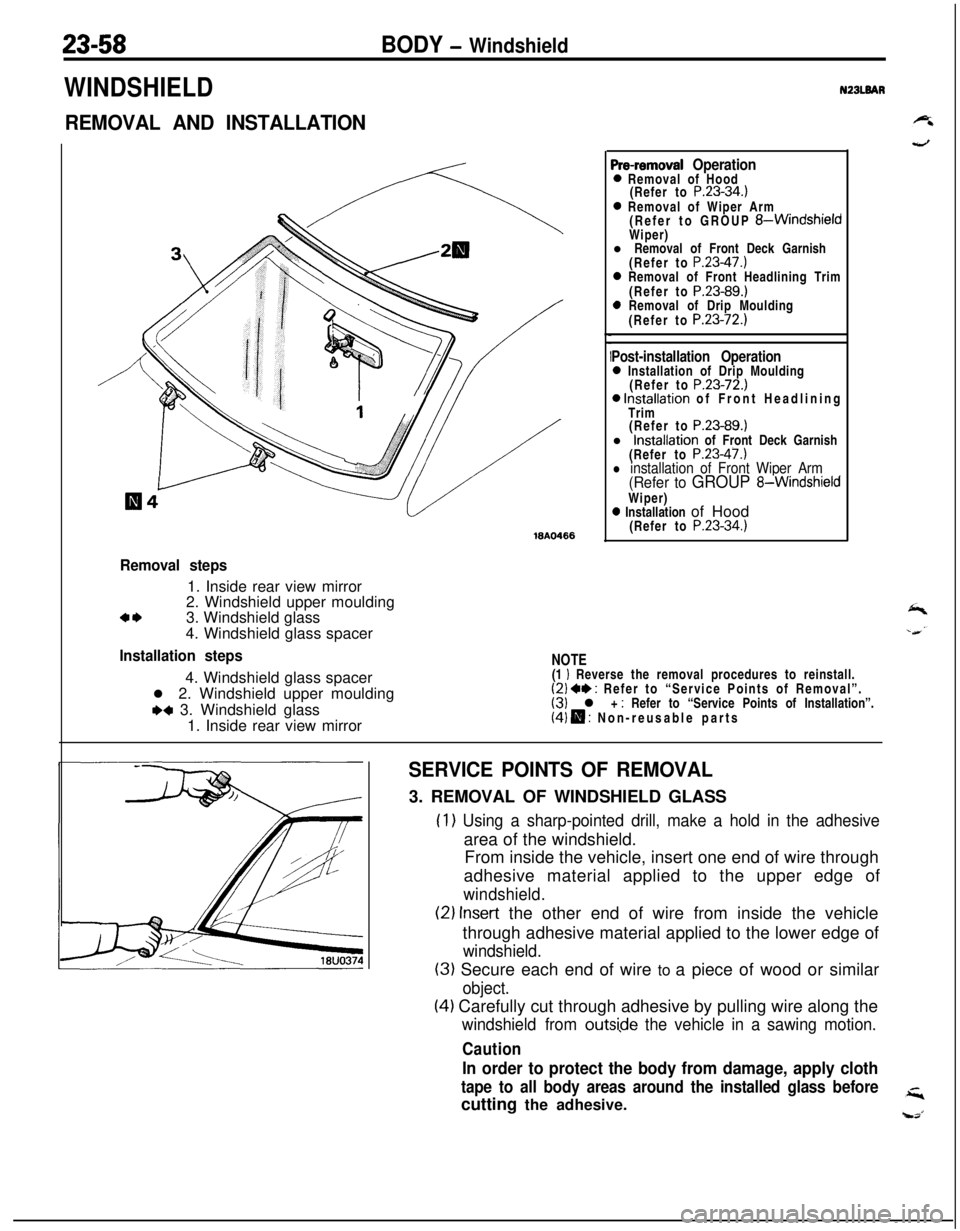
Removal steps1. Inside rear view mirror
2. Windshield upper moulding
a*3. Windshield glass
4. Windshield glass spacer
Installation steps4. Windshield glass spacer
l 2. Windshield upper moulding
+a 3. Windshield glass
1. Inside rear view mirror
NOTE(1 I Reverse the removal procedures to reinstall.(2) +* : Refer to “Service Points of Removal”.(3) l + : Refer to “Service Points of Installation”.(4) H : Non-reusable parts
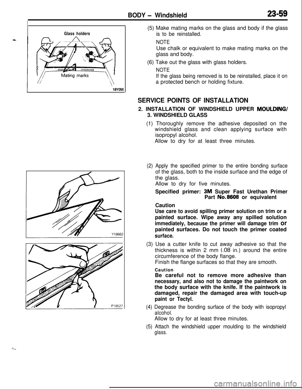
SERVICE POINTS OF REMOVAL3. REMOVAL OF WINDSHIELD GLASS
(1) Using a sharp-pointed drill, make a hold in the adhesivearea of the windshield.
From inside the vehicle, insert one end of wire through
adhesive material applied to the upper edge of
windshield.
(2) Insert the other end of wire from inside the vehicle
through adhesive material applied to the lower edge of
windshield.
(3) Secure each end of wire to a piece of wood or similar
object.
(4) Carefully cut through adhesive by pulling wire along the
windshield from outsi,de the vehicle in a sawing motion.
Caution
In order to protect the body from damage, apply cloth
tape to all body areas around the installed glass beforecutting the adhesive.
Page 1103 of 1216
BODY - Windshield
Glass holders
,(5) Make mating marks on the glass and body if the glass
is to be reinstalled.
NOTEUse chalk or equivalent to make mating marks on the
glass and body.
(6) Take out the glass with glass holders.
NOTE
If the glass being removed is to be reinstalled, place it ona protected bench or holding fixture.
SERVICE POINTS OF INSTALLATION2. INSTALLATION OF WINDSHIELD UPPER MOULDING/
3. WINDSHIELD GLASS
(1) Thoroughly remove the adhesive deposited on the
windshield glass and clean applying surface with
isopropyl alcohol.
Allow to dry for at least three minutes.
(2) Apply the specified primer to the entire bonding surfaceof the glass, both to the inside surface and the edge of
the glass.
Allow to dry for five minutes.
Specified primer:
3M Super Fast Urethan Primer
CautionPart No.8608 or equivalent
Use care to avoid spilling primer solution on trim or apainted surface. Wipe away any spilled solution
immediately, because the primer will damage trim orpainted surfaces. Do not touch the primer coated
surface.(3) Use a cutter knife to cut away adhesive so that the
thickness is within 2 mm
(.08 in.) around the entire
circumference of the body flange.
Finish the flange surfaces so that they are smooth.
Caution
Be careful not to remove more adhesive than
necessary, and also not to damage the paintwork onthe body surface with the knife. If the paintwork is
damaged, repair the damaged area with touch-up
paint or Tectyl.
(4) Degrease the bonding surface of the body with isopropyl
alcohol.Allow to dry for at least three minutes.
(5) Attach the windshield upper moulding to the windshield
glass.