engine coolant MITSUBISHI ECLIPSE 1991 Repair Manual
[x] Cancel search | Manufacturer: MITSUBISHI, Model Year: 1991, Model line: ECLIPSE, Model: MITSUBISHI ECLIPSE 1991Pages: 1216, PDF Size: 67.42 MB
Page 532 of 1216
FUEL SYSTEM - MPI System Inspection <2.0L DOHC Engine>
6FUO999
Accelerator pedal
DepressedContinuity .
Non-conductive
(03 fl)
ReleasedIConductive (0 fl)I(4) Replace the idle position switch if faulty.
NOTE
For replacement procedure, refer to the idle position switch(fixed speed adjusting screw) adjustment section
(P.14-
52.).OXYGEN SENSOR
NllQDeJ
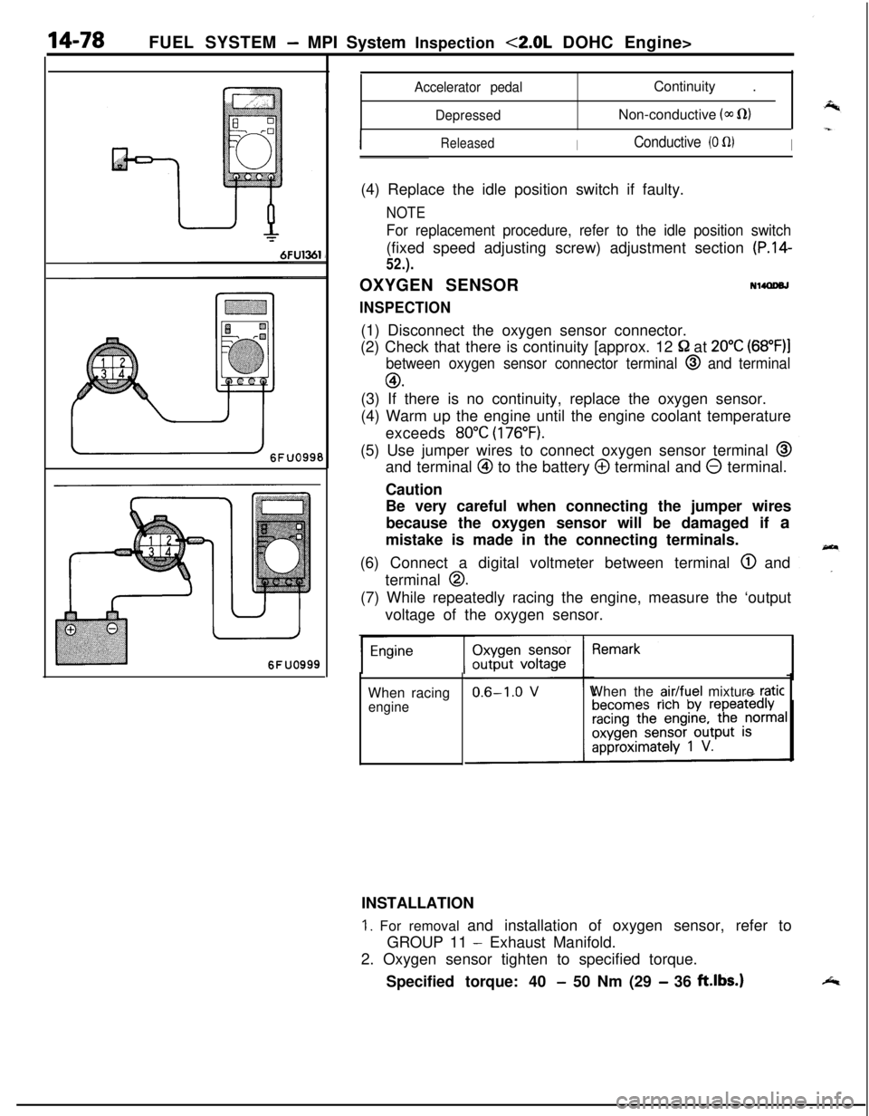
INSPECTION(1) Disconnect the oxygen sensor connector.
(2) Check that there is continuity [approx. 12
52 at 20°C (68”F)l
between oxygen sensor connector terminal @ and terminal
GO.(3) If there is no continuity, replace the oxygen sensor.
(4) Warm up the engine until the engine coolant temperature
exceeds
80°C (176°F).(5) Use jumper wires to connect oxygen sensor terminal
@and terminal
@ to the battery @ terminal and 0 terminal.
Caution
Be very careful when connecting the jumper wires
because the oxygen sensor will be damaged if a
mistake is made in the connecting terminals.
(6) Connect a digital voltmeter between terminal
@ and
terminal
0.(7) While repeatedly racing the engine, measure the ‘output
voltage of the oxygen sensor.
When racing
engineWhen the
air/fuel mixture raticINSTALLATION
1. For removal and installation of oxygen sensor, refer to
GROUP 11
- Exhaust Manifold.
2. Oxygen sensor tighten to specified torque.
Specified torque: 40
- 50 Nm (29 - 36 ft.lbs.)
Page 896 of 1216
21-202AUTOMATIC TRANSAXLE - Troubleshooting
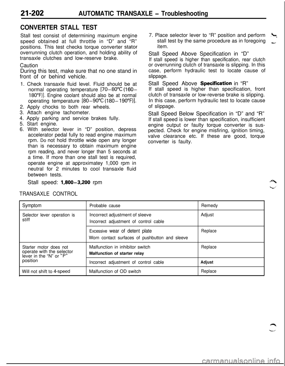
CONVERTER STALL TESTStall test consist of determining maximum engine
speed obtained at full throttle in “D” and “R”
positions. This test checks torque converter stator
overrunning clutch operation, and holding ability of
transaxle clutches and low-reserve brake.
CautionDuring this test, make sure that no one stand in
front of or behind vehicle.
1. Check transaxle fluid level. Fluid should be at
normal operating temperature
[70-80°C (160-
18O”F)]. Engine coolant should also be at normaloperating temperature
[80-90°C (180- 19O”F)l.2. Apply chocks to both rear wheels.
3. Attach engine tachometer.
4. Apply parking and service brakes fully.
5. Start engine.
6. With selector lever in “D” position, depress
accelerator pedal fully to read engine maximum
rpm. Do not hold throttle wide open any longer
than is necessary to obtain maximum engine
rpm reading, and never longer than 5 seconds ata time. If more than one stall test is required,
operate engine at approximatey 1,000 rpm in
neutral for 2 minutes to cool transaxle fluid
between tests.
Stall speed:
1,800-3,200 rpm
TRANSAXLE CONTROL7. Place selector lever to “R” position and perform
?+stall test by the same procedure as in foregoing
-,
item.Stall Speed Above Specification in “D”
If stall speed is higher than specification, rear clutchor overrunning clutch of transaxle is slipping. In this
case, perform hydraulic test to locate cause of
slippage.Stall Speed Above Specifjcation in “R”
If stall speed is higher than specification, front
clutch of transaxle or low-reverse brake is slipping.
In this case, perform hydraulic test to locate cause
of slippage.
Stall Speed Below Specification in “D” and “R”
If stall speed is lower than specification, insufficient
engine output or faulty torque converter is sus-
pected. Check for engine misfiring, ignition timing,
valve clearance etc. If these are good, torque
converter is faulty.
Symptom
Selector lever operation isstiff
Probable causeIncorrect adjustment of sleeve
Incorrect adjustment of control cable
Excessive wear of detent plate
Worn contact surfaces of pushbutton and sleeveRemedyAdjust
Replace
Starter motor does notoperate with the selector
lever in the “N” or
“P”position
Will not shift to
4-speedMalfunction in inhibitor switch
Malfunction of starter relay
Incorrect adjustment of control cableMalfunction of OD switch
Replace
Adjust
Replace
Page 1145 of 1216

24-l
HEATERS ANDAIR CONDITIONING
CONTENTSN24M--AIR CONDITIONER SWITCH
..........................30BLOWER ASSEMBLY
.....................................33
COMPRESSOR.................................................37CONDENSER AND CONDENSER FAN
MOTOR............................................................45ENGINE COOLANT TEMPERATURE
-‘-.,SWITCH............................................................51
EVAPORATOR.................................................
34
HEATERCONTROLASSEMBLY....................
26HEATER UNIT
.................................................31
REFRIGERANTLINE........................................47
RESISTOR........................................................29SAFETY PRECAUTIONS
.................................10SERVICE ADJUSTMENT PROCEDURES..
.....11Compressor Drive
Belt Adjustment
.............
23
CompressorNoise........................................24
Handling
TubingandFittings.......................22Idle-up
OperationCheck..............................25Manifold
GaugeSetInstallation..................11Performance Test
.........................................16Power Relay Check
......................................24Refrigerant Leak Repair Procedure
.............17
TestingSystemforLeaks...........................15Test Procedures
...........................................11
SPECIFICATIONS.............................................2
General Specifications..................................2
Lubricants......................................................3Sealant and Adhesives
.................................3Service Specifications
...................................2
TorqueSpecifications...................................2
TROUBLESHOOTING. . . ..a................................3
VENTILATORS(AIR INLET AND AIR OUTLET)
..,....s............. 50
VENTILATORS(INSTRUMENT PANEL)
..,...................*...........49
Page 1146 of 1216
24-2HEATERS AND AIR CONDITIONING - Specifications
SPECIFICATIONS
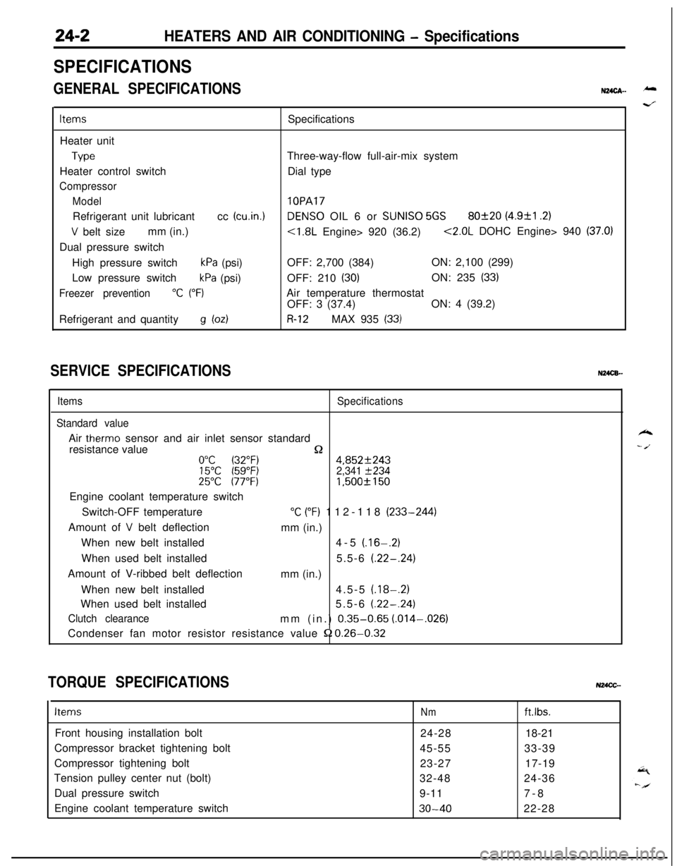
GENERAL SPECIFICATIONSN24cA- -
ItemsSpecifications
Heater unit
TypeThree-way-flow full-air-mix system
Heater control switchDial type
Compressor
Model
lOPARefrigerant unit lubricantcc
(cu.in.1DENS0 OIL 6 or SUNISO 5GS80f20 (4.9&l .2)
V belt sizemm (in.)<1.8L Engine> 920 (36.2)<2.0L DOHC Engine> 940 (37.0)Dual pressure switch
High pressure switch
kPa (psi)OFF: 2,700 (384)ON: 2,100 (299)
Low pressure switch
kPa (psi)OFF: 210 (30)ON: 235 (33)
Freezer prevention“C (“F)Air temperature thermostat
OFF: 3 (37.4)ON: 4 (39.2)
Refrigerant and quantity
g bdR-12MAX 935 (33)
SERVICE SPECIFICATIONSN24CB.-
ItemsSpecifications
Standard valueAir
therm0 sensor and air inlet sensor standard
resistance value
n0°C (32°F)4,852f24315°C (59°F)2,341 f23425°C 177°F)1,500f 150Engine coolant temperature switch
Switch-OFF temperature
“C (“F) 112-118 (233-244)
Amount of
V belt deflection
mm (in.)
When new belt installed4-5
(.16-.2)When used belt installed5.5-6
(.22-.24)Amount of V-ribbed belt deflection
mm (in.)
When new belt installed4.5-5
(.18-.2)When used belt installed5.5-6
(.22-.24)
Clutch clearancemm (in.) 0.35-0.65 (.014-,026)
Condenser fan motor resistor resistance value
52 0.26-0.32
TORQUE SPECIFICATIONSN24CC-
ItemsNmft.lbs.Front housing installation bolt
24-2818-21
Compressor bracket tightening bolt
45-5533-39
Compressor tightening bolt
23-2717-19
Tension pulley center nut (bolt)
32-4824-36
Dual pressure switch
9-117-8
Engine coolant temperature switch
30-4022-28
k
- /.
Page 1147 of 1216

HEATERS AND AIR CONDITIONING - Specifications/Troubleshooting24-3LUBRICANTS
u24as-
;xiItemsSpecified lubricantsQuantity
Each connection of refrigerant lineDENS0 OIL 6 or
SUNISO 5GSAs required
Shaft seal of the compressor
SEALANT AND ADHESIVES, Items
Engine coolant temperature switch threaded partSpecified sealant and adhesive
MOPAR Part No.4318034 or equivalentN24CE-
TROUBLESHOOTINGN24EBAQ
SymptomHeater insufficient heat
No ventilation even when
mode selection knob is
operatedBlower motor inoperative
Probable causeObstructed heater outlets
Blend air dampers improperly adjusted or bindingThermostat malfunction
Obstructed heater hoses
Improperly adjusted control cables
Plugged or partially plugged heater core
Incorrect adjustment of mode selection dampersIncorrect installation of mode selection control wire
Ducts are incorrectly/incompletely connected, crushed,
bent or clogged.
Poor grounding
Burnt-out fuseMalfunction blower switch
Malfunction resister
Malfunction blower motor
Malfunction heater relay
Remedy
Correct
ReplaceAdjust
Clean or replaceAdjust
Repair or replace
Correct
Replace
Page 1152 of 1216
24-8HEATERS AND AIR CONDITIONING - Troubleshooting
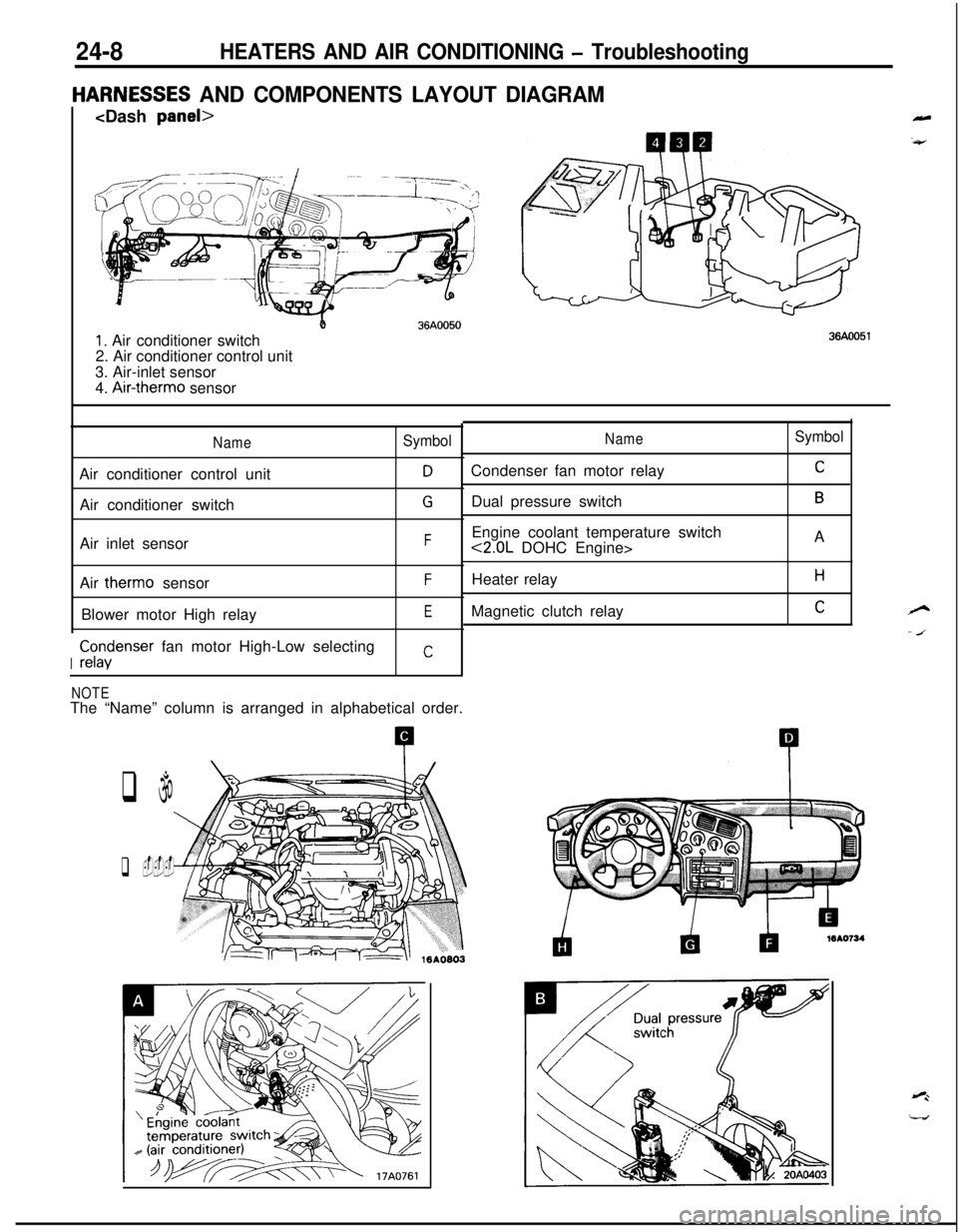
IARNESSES AND COMPONENTS LAYOUT DIAGRAM
1. Air conditioner switch
2. Air conditioner control unit
3. Air-inlet sensor
4.
Air-therm0 sensor
36AOO51
NameSymbolAir conditioner control unit
DAir conditioner switch
GAir inlet sensor
FAir
therm0 sensorFBlower motor High relay
E
IrrIor:enser fan motor High-Low selecting
C
NameCondenser fan motor relay
Dual pressure switch
Engine coolant temperature switch
<2.0L DOHC Engine>
Heater relay
Magnetic clutch relay
Symbol
C
BA
H
C
NOTEThe “Name” column is arranged in alphabetical order.
q \
q ---
Page 1157 of 1216
HEATERS AND AIR CONDITIONING - Service Adjustment Procedures 249*I3
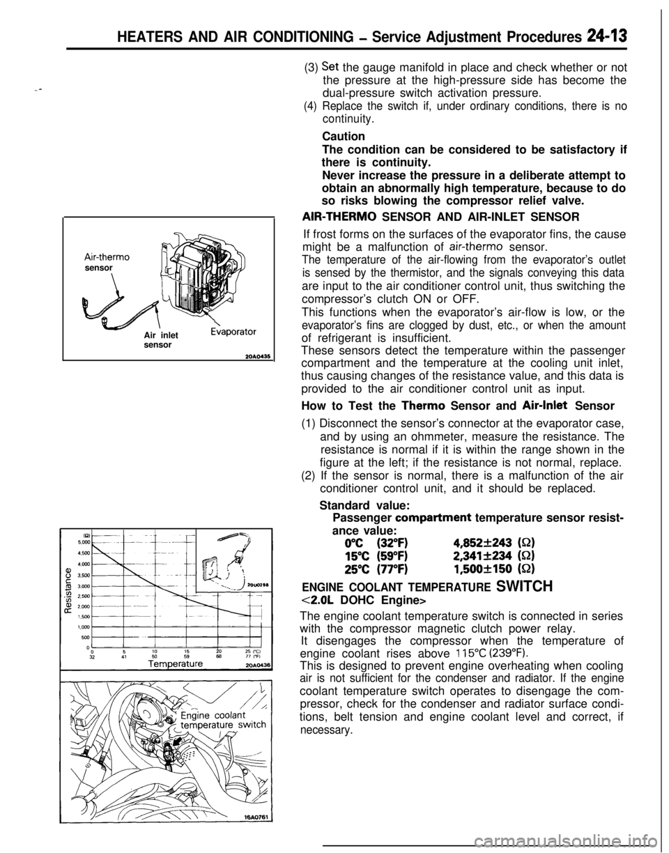
--Air-therm0
sensor
Air inlet
sensor
E>aporator(3)
Set the gauge manifold in place and check whether or not
the pressure at the high-pressure side has become the
dual-pressure switch activation pressure.
(4) Replace the switch if, under ordinary conditions, there is no
continuity.Caution
The condition can be considered to be satisfactory if
there is continuity.
Never increase the pressure in a deliberate attempt to
obtain an abnormally high temperature, because to do
so risks blowing the compressor relief valve.AIR-THERM0 SENSOR AND AIR-INLET SENSOR
If frost forms on the surfaces of the evaporator fins, the cause
might be a malfunction of
air-therm0 sensor.
The temperature of the air-flowing from the evaporator’s outlet
is sensed by the thermistor, and the signals conveying this dataare input to the air conditioner control unit, thus switching the
compressor’s clutch ON or OFF.
This functions when the evaporator’s air-flow is low, or the
evaporator’s fins are clogged by dust, etc., or when the amountof refrigerant is insufficient.
These sensors detect the temperature within the passenger
compartment and the temperature at the cooling unit inlet,
thus causing changes of the resistance value, and this data is
provided to the air conditioner control unit as input.
How to Test the Therm0 Sensor and Air-Inlet Sensor
(1) Disconnect the sensor’s connector at the evaporator case,
and by using an ohmmeter, measure the resistance. The
resistance is normal if it is within the range shown in the
figure at the left; if the resistance is not normal, replace.
(2) If the sensor is normal, there is a malfunction of the air
conditioner control unit, and it should be replaced.
Standard value:
Passenger compartment temperature sensor resist-
ance value:
0°C (32°F)4,852+243 (S-2)
15°C (59°F)2,341+234 (S-2)
25°C (77°F)1,500+150 (52)
ENGINE COOLANT TEMPERATURE SWITCH
<2.0L DOHC Engine>
The engine coolant temperature switch is connected in series
with the compressor magnetic clutch power relay.
It disengages the compressor when the temperature of
engine coolant rises above
115°C (239°F).This is designed to prevent engine overheating when cooling
air is not sufficient for the condenser and radiator. If the enginecoolant temperature switch operates to disengage the com-
pressor, check for the condenser and radiator surface condi-
tions, belt tension and engine coolant level and correct, if
necessary.
Page 1169 of 1216
HEATERS AND AIR CONDITIONING - Service Adjustment Procedures 24-25
16A1077
20AO499
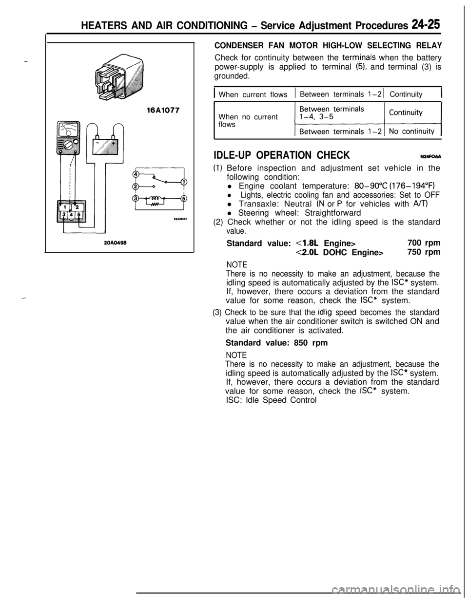
CONDENSER FAN MOTOR HIGH-LOW SELECTING RELAYCheck for continuity between the
term,inals when the battery
power-supply is applied to terminal
(5), and terminal (3) is
grounded.
IWhen current flows1 Between terminals l-2 1 Continuity1When no current
flows
IDLE-UP OPERATION CHECKN24FoAA
(I) Before inspection and adjustment set vehicle in the
following condition:
l Engine coolant temperature:
80-90°C (176-194°F)
lLights, electric cooling fan and accessories: Set to OFFl Transaxle: Neutral
(N or P for vehicles with A/T)l Steering wheel: Straightforward
(2) Check whether or not the idling speed is the standard
value.Standard value:
4.8L Engine>700 rpm
<2.0L DOHC Engine>750 rpm
NOTE
There is no necessity to make an adjustment, because theidling speed is automatically adjusted by the
ISC” system.
If, however, there occurs a deviation from the standard
value for some reason, check the
ISC” system.
(3) Check to be sure that the idlig speed becomes the standardvalue when the air conditioner switch is switched ON and
the air conditioner is activated.
Standard value: 850 rpm
NOTE
There is no necessity to make an adjustment, because theidling speed is automatically adjusted by the
ISC” system.
If, however, there occurs a deviation from the standard
value for some reason, check the
ISC” system.
ISC: Idle Speed Control
Page 1175 of 1216
HEATERS AND AIR CONDITIONING - Heater Unit24-31
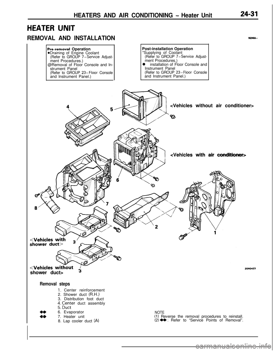
HEATER UNIT
REMOVAL AND INSTALLATIONN24m-
Pre-removal OperationeDraining of Engine Coolant(Refer to GROUP 7-Service Adjust-ment Procedures.)
@Removal of Floor Console and In-
strument Panel
(Refer to GROUP 23-Floor Consoleand Instrument Panel.)Post-installation Operation
*Supplying of Coolant
(Refer to GROUP 7-Service Adjust-ment Procedures.)
l installation of Floor Console and
Instrument Panel
(Refer to GROUP 23-Floor Consoleand Instrument Panel.)
shower duct>
Jshower duct>
Removal steps
1. Center reinforcement
2. Shower duct (R.H.)
3. Distribution foot duct
;: ;Z;;er duct assembly
:z6. Evaporator
7. Heater unit
8. Lap cooler duct (A)
NOTE(1) Reverse the removal procedures to reinstall.(2) 4* : Refer to “Service Points of Removal”.
Page 1195 of 1216
HEATERS AND AIR CONDITIONING- Engine Coolant Temperature Switch24-51
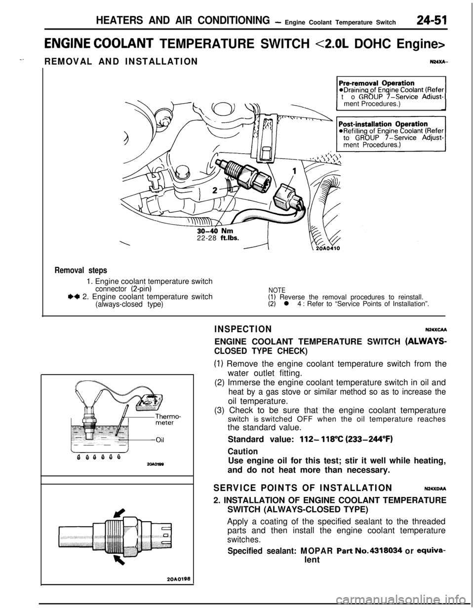
ENGINE COOLANT TEMPERATURE SWITCH <2.0L DOHC Engine>
-.REMOVAL AND INSTALLATIONN24xA-
1 to GROUP f-service Adjust-1ment Procedures.)
22-28
ft.lbs.
Removal steps1. Engine coolant temperature switch
connector (2-pin)
.4 2. Engine coolant temperature switch(always-closed type)
NOTE(1) Reverse the removal procedures to reinstall.(2) l 4 : Refer to “Service Points of Installation”.
20A0190I
INSPECTIONN24XcAAENGINE COOLANT TEMPERATURE SWITCH
(ALWAYS-
CLOSED TYPE CHECK)
(1) Remove the engine coolant temperature switch from the
water outlet fitting.
(2) Immerse the engine coolant temperature switch in oil and
heat by a gas stove or similar method so as to increase theoil temperature.
(3) Check to be sure that the engine coolant temperature
switch is switched OFF when the oil temperature reaches
the standard value.
Standard value:
112- 118°C (233-244°F)
CautionUse engine oil for this test; stir it well while heating,
and do not heat more than necessary.
SERVICE POINTS OF INSTALLATIONN24XDM2. INSTALLATION OF ENGINE COOLANT TEMPERATURE
SWITCH (ALWAYS-CLOSED TYPE)
Apply a coating of the specified sealant to the threaded
parts and then install the engine coolant temperature
switches.
Specified sealant: MOPAR Part No.4318034 or ewiva-lent