battery MITSUBISHI ECLIPSE 1991 Service Manual
[x] Cancel search | Manufacturer: MITSUBISHI, Model Year: 1991, Model line: ECLIPSE, Model: MITSUBISHI ECLIPSE 1991Pages: 1216, PDF Size: 67.42 MB
Page 14 of 1216
I4INTRODUCTION AND MASTER TROUBLESHOOTING - Precautions before Service
mm (In.1smo59
PARTSWhen replacing parts, use MOPAR genuine parts.
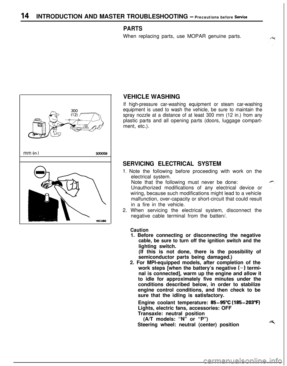
VEHICLE WASHING
If high-pressure car-washing equipment or steam car-washing
equipment is used to wash the vehicle, be sure to maintain the
spray nozzle at a distance of at least 300 mm (12 in.) from anyplastic parts and all opening parts (doors, luggage compart-
ment, etc.).
SERVICING ELECTRICAL SYSTEM
1. Note the following before proceeding with work on the
electrical system.
Note that the following must never be done:
Unauthorized modifications of any electrical device or
wiring, because such modifications might lead to a vehicle
malfunction, over-capacity or short-circuit that could result
in a fire in the vehicle.
2. When servicing the electrical system, disconnect the
negative cable terminal from the batten/.
Caution1. Before connecting or disconnecting the negative
cable, be sure to turn off the ignition switch and thelighting switch.
(If this is not done, there is the possibility of
semiconductor parts being damaged.)
2. For MPI-equipped models, after completion of the
work steps [when the battery’s negative
(-) termi-
nal is connected], warm up the engine and allow it
to idle for approximately five minutes under the
conditions described below, in order to stabilize
engine control conditions, and then check to be
sure that the idling is satisfactory.
Engine coolant temperature:
85-95°C (185-203°F)
Lights, electric fans, accessories: OFF
Transaxle: neutral position
(A/T models: “N” or “P”)
Steering wheel: neutral (center) position
Page 141 of 1216
BRAKES
SERVICE AND PARKING
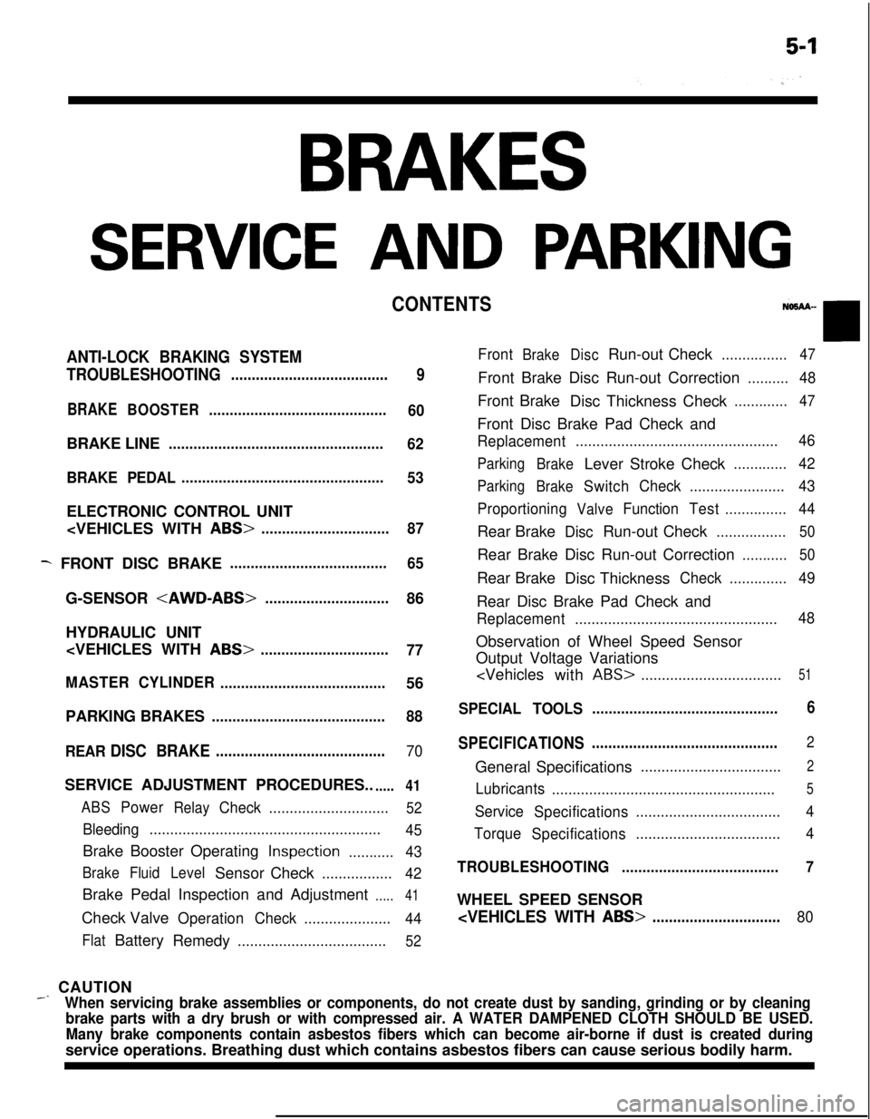
CONTENTS
ANTI-LOCK BRAKING SYSTEM
TROUBLESHOOTING
......................................
9
BRAKEBOOSTER...........................................
60BRAKE LINE
....................................................
62
BRAKE PEDAL.................................................
53ELECTRONIC CONTROL UNIT
- FRONT DISC BRAKE......................................
65G-SENSOR
HYDRAULIC UNIT
77
MASTERCYLINDER
........................................56
PARKING BRAKES
..........................................88
REAR
DISC BRAKE.........................................70SERVICE ADJUSTMENT PROCEDURES..
.....41
ABSPowerRelayCheck.............................52
Bleeding........................................................
45Brake Booster Operating
Inspection...........43
BrakeFluidLevelSensor Check.................
42Brake Pedal Inspection and Adjustment
.....41Check Valve
OperationCheck.....................
44
FlatBattery
Remedy....................................52
FrontBrakeDiscRun-out Check................47Front Brake Disc Run-out Correction
..........48Front Brake
Disc Thickness Check
.............47Front Disc Brake Pad Check and
Replacement.................................................46
Parking
BrakeLever Stroke Check.............42
Parking
BrakeSwitchCheck.......................43
Proportioning
ValveFunctionTest...............44Rear Brake
DiscRun-out Check.................50Rear Brake Disc Run-out Correction
...........50Rear Brake
Disc Thickness
Check..............49Rear Disc Brake Pad Check and
Replacement.................................................48Observation of Wheel Speed Sensor
Output Voltage Variations
ABS>..................................51
SPECIAL TOOLS.............................................6
SPECIFICATIONS.............................................
2General Specifications
..................................2
Lubricants
......................................................5
Service
Specifications...................................4
Torque
Specifications...................................4
TROUBLESHOOTING......................................7WHEEL SPEED SENSOR
_ CAUTION
When servicing brake assemblies or components, do not create dust by sanding, grinding or by cleaning
brake parts with a dry brush or with compressed air. A WATER DAMPENED CLOTH SHOULD BE USED.
Many brake components contain asbestos fibers which can become air-borne if dust is created duringservice operations. Breathing dust which contains asbestos fibers can cause serious bodily harm.
Page 153 of 1216
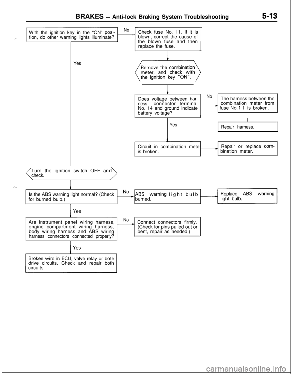
BRAKES - Anti-lock Braking System Troubleshooting5-13With the ignition key in the “ON”
posi-Nol
tion, do other warning lights illuminate?
II
YesCheck fuse No. 11. If it is
blown, correct the cause of
the blown fuse and then
replace the fuse.
Does voltage between
har-NoThe harness between thenessconnector terminalcombination meter from
No. 14 and ground indicate) fuse No.1 1 is broken.
battery voltage?
II
Yes
Repair harness.Circuit in combination meter
is broken.Repair or replace
com-
* bination meter.
Turn the ignition switch OFF an
(check.
IIs the ABS warning light normal? (Check
for burned bulb.)
No L A&zed%rning light bulb -Are instrument panel wiring harness,
_Noengine compartment wiring harness,~ Connect connectors firmly.
(Check for pins pulled out or
bent, repair as needed.) body wiring harness and ABS wiring
harness connectors connected properly?drive circuits. Check and repair both
Page 154 of 1216
5-14BRAKES - Anti-lock Braking System Troubleshooting
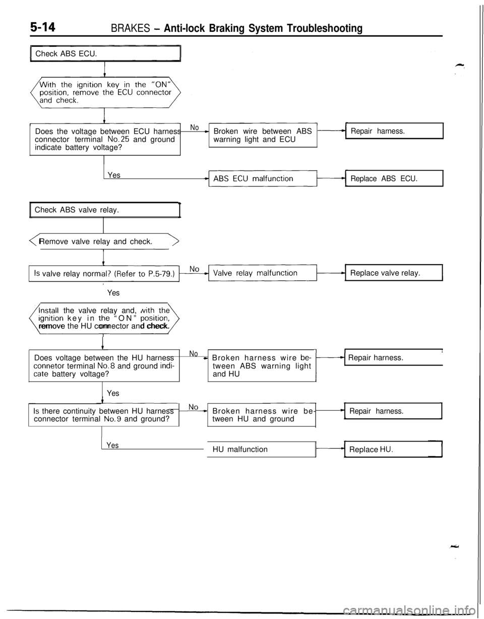
aCheck ABS ECU.
Does the voltage between ECU harness
Not Broken wire between ABSRepair harness.connector terminal No.25 and groundwarning light and ECU
indicate battery voltage?
Yes
Replace ABS ECU.Check ABS valve relay.
I
Is valve relay normReplace valve relay.I
YesInstall the valve relay and, with the
(gnition key in the “ON” position>remove the HU connector and check.
IDoes voltage between the HU harnessNow Broken harness wire be-connetor terminal No.8 and ground
indi-tween ABS warning light
cate battery voltage?and HU
Yes
7II1/---I Repair harness.
Is there continuity between HU harnessNo* Broken harness wire be-Repair harness.connector terminal No.9 and ground?tween HU and groundI
YesHU malfunction
Replace HU.
Page 156 of 1216
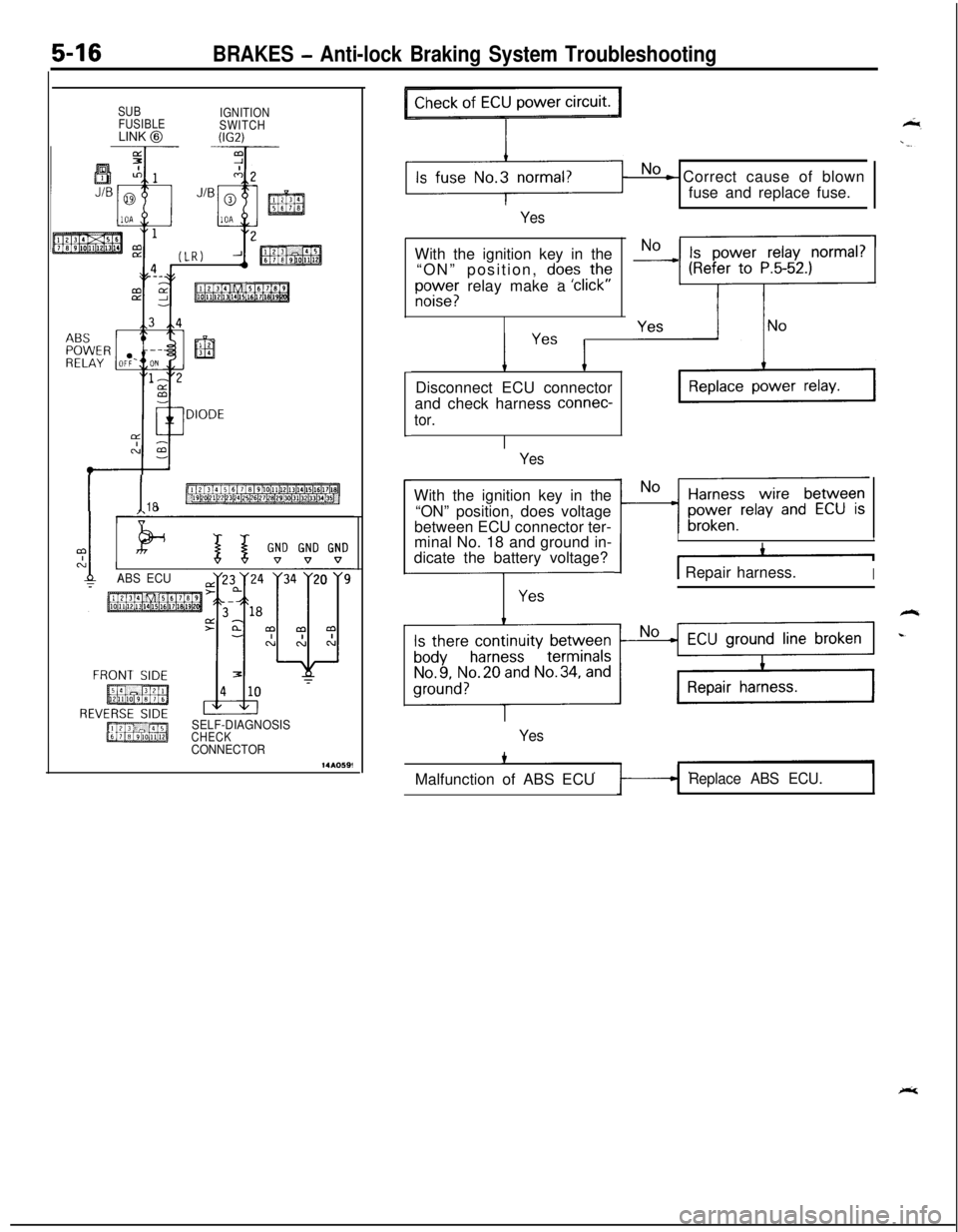
5-16BRAKES - Anti-lock Braking System Troubleshooting
SUB
IGNITION
FUSIBLE
SWITCHLINK
@W.2)
I I18
ABS ECU9
SELF-DIAGNOSISCHECKCONNECTOR
No - Correct cause of blown
fuse and replace fuse.
YesWith the ignition key in the
“ON” position,
does ,thf
E;;;; relay make a click
’ Yes ’Disconnect ECU connector
and check harness
connec-
tor.
YesWith the ignition key in the
“ON” position, does voltage
between ECU connector ter-
minal No. 18 and ground in-
dicate the battery voltage?
---j-z-
III
I -11 Repair harness.I
YesMalfunction of ABS ECU
Replace ABS ECU.
Page 157 of 1216
![MITSUBISHI ECLIPSE 1991 Service Manual BRAKES - Anti-lock Braking System Troubleshooting5-17
CABS warning light does not illuminate when ignition key is in “START” position.
-.[Explanation]
The ABS ECU uses the
IG2 power source which MITSUBISHI ECLIPSE 1991 Service Manual BRAKES - Anti-lock Braking System Troubleshooting5-17
CABS warning light does not illuminate when ignition key is in “START” position.
-.[Explanation]
The ABS ECU uses the
IG2 power source which](/img/19/57104/w960_57104-156.png)
BRAKES - Anti-lock Braking System Troubleshooting5-17
CABS warning light does not illuminate when ignition key is in “START” position.
-.[Explanation]
The ABS ECU uses the
IG2 power source which is
turned off in the “START” position. The ABS
warning light uses the
IGI power source which is
not turned off even in the “START” position.
Consequently, in the “START” position, power is offand the ECU turns the valve relay OFF. If the
warning light does not illuminate at this time, there
is trouble in the warning light circuit on the valve
relay side.
MAINIGNITIONFUSIBLESWITCHLINK @(iG1)I
J/B58
15
ABS ECUWith the ignition key in the
“ON” position, does voltagebetween body connector
terminal
No.8 and groundindicate the battery voltage?
Yes
Page 158 of 1216
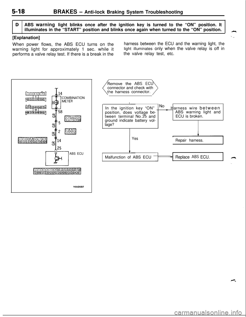
5-18BRAKES - Anti-lock Braking System Troubleshooting
DABS warning light blinks once after the ignition key is turned to the “ON” position. It
illuminates in the “START” position and blinks once again when turned to the “ON” position.
[Explanation]
When power flows, the ABS ECU turns on the
harness between the ECU and the warning light, thewarning light for approximately 1 sec. while itlight illuminates only when the valve relay is off in
performs a valve relay test. If there is a break in thethe valve relay test, etc.
125
El
ABS ECU
14A0597connector and check with
I
In the ignition key “ON”
_ No ~ Harness wire between
position, does voltage
be-ABS warning light and
tween terminal No.25 andECU is broken.
ground indicate battery vol-
tage?
YesRepair harness.
tMalfunction of ABS ECU
Replace ABS ECU.
Page 161 of 1216
![MITSUBISHI ECLIPSE 1991 Service Manual BRAKES - Anti-lock Braking System Troubleshooting5-g
E-3Abnormality of stop light switch circuit
_ [Explanation][Hint]The ABS ECU turns on the warning light in theIf the stop light operates normal, th MITSUBISHI ECLIPSE 1991 Service Manual BRAKES - Anti-lock Braking System Troubleshooting5-g
E-3Abnormality of stop light switch circuit
_ [Explanation][Hint]The ABS ECU turns on the warning light in theIf the stop light operates normal, th](/img/19/57104/w960_57104-160.png)
BRAKES - Anti-lock Braking System Troubleshooting5-g
E-3Abnormality of stop light switch circuit
_ [Explanation][Hint]The ABS ECU turns on the warning light in theIf the stop light operates normal, the ABS harness
following cases.
wire for the stop light switch input circuit to the ECUlStop light switch may remain on for more than
is broken or there is a malfunction in the ABS ECU.15 minutes without the ABS functions.
lThe harness wire for the stop light switch may
be open.
T AUTO-
TOPIGHT
WITCH
ABSECUDo the stop lights light up
Noand go out normally?c Check the stop light re-lated circuit and repair
Iproblem spots.
the ABS
ECUconnector and inspect at
>the harness side connec-
L No
When the brake pedal is
pressed
forcefullv, does thevoltage between’ connector
terminal No. 29 and ground
indicate battery voltage?Harness wire between
* stop light switch and ABS
ECU is broken.
J1 Repair harness.I
Yes
IStop light switch circuit isnormal.l
Page 163 of 1216
![MITSUBISHI ECLIPSE 1991 Service Manual BRAKES - Anti-lock Braking System Troubleshooting5-23
E-5Abnormality of valve relay drive circuit
~- [Explanation]Ii ;.
\jVhen the ignition switch is turned ON, the ABSnormal. In addition, normally it MITSUBISHI ECLIPSE 1991 Service Manual BRAKES - Anti-lock Braking System Troubleshooting5-23
E-5Abnormality of valve relay drive circuit
~- [Explanation]Ii ;.
\jVhen the ignition switch is turned ON, the ABSnormal. In addition, normally it](/img/19/57104/w960_57104-162.png)
BRAKES - Anti-lock Braking System Troubleshooting5-23
E-5Abnormality of valve relay drive circuit
~- [Explanation]Ii ;.
\jVhen the ignition switch is turned ON, the ABSnormal. In addition, normally it monitors whether qrECU switches the valve relay OFF and ON for annot there is power in the valve power monitor line
initial check, compares the voltage of the signal tosince the valve relay is normally ON. Then, if the
the valve relay and valve power monitor line voltagesupply of power to the valve power monitor,line is
tocheck whether the valve relay operation isinterrupted, the warning light illuminates.
IGNITIONMiN&USIBLESWITCH(IGI)
ECU
1When the valve relay is
checked, are the following
conditions found?Valve relay malfunction
I
No. 85-No. 86:resistancevalue 60-120 QNo. 30-No. 87a: continuity
No. 30-No. 87: No continui-
tYWhen battery voltage is ap-
plied between terminals
No. 86 and No. 85 grounded.No.
30-No. 87: continuity
No. 30-No. 87a: no continui-
Install the valve relay and
remove the HU connec-
t the HU harnesandremove the ECU con-Is there continuity between
body connector terminal No.
22 and ground?
Yes
Valve relay drive circuit is
normal.
Page 164 of 1216
![MITSUBISHI ECLIPSE 1991 Service Manual 5-24BRAKES - Anti-lock Braking System Troubleshooting
E-6 Abnormality of motor drive circuit
[Explanation]The ABS ECU illuminates the warning light for the
motor relay and motor in the following cases MITSUBISHI ECLIPSE 1991 Service Manual 5-24BRAKES - Anti-lock Braking System Troubleshooting
E-6 Abnormality of motor drive circuit
[Explanation]The ABS ECU illuminates the warning light for the
motor relay and motor in the following cases](/img/19/57104/w960_57104-163.png)
5-24BRAKES - Anti-lock Braking System Troubleshooting
E-6 Abnormality of motor drive circuit
[Explanation]The ABS ECU illuminates the warning light for the
motor relay and motor in the following cases.
l When the motor relay does not function
lWhen there is trouble with the motor itself and it
does not revolve
lWhen the motor ground line is disconnected and
[Hint]If there is motor operation noise when wheel speed
exceeds
Gkm/h (4mph) when starting up after the
engine is started, there is a broken or short circuitedmotor monitor wire.
the motor does not revolve
l When the motor continues to revolve
14A0605Does the motor make a
YesBroken wire or short cir-noise when wheel speedcuit in motor monitor line
exceeds 6 km/h (4 mph)?
1Repair the harness be-
tween HU and ECU.
, NoRemove the motor relay.
Remove the motor relay andcheck resistance values.
No. 85-No. 86:resistancevalue
30-60 52No.30-No.87: no continui-
ty
Battery voltage is applied onterminals No. 86 and No.85
grounded.No.30-No.87: continuity
IYesIs pump motor ground con-
NoConnect ground wire.
netted normally?
IlYes
motor relay and re-
move HU connector.>Does voltage between body
connector terminal 51 and
No c Broken wire in pump
motor power circuit
ground indicate battery vol-
tage?4Repair the harness.
YesIs resistance between body
NoMalfunction of harnessconnector terminal No. 2 andbetween HU and ECUNo.26 30-60 ohms?iII1Repair harness.