23-80BODY - Instrument Panel
REMOVAL AND INSTALLATION
-?7
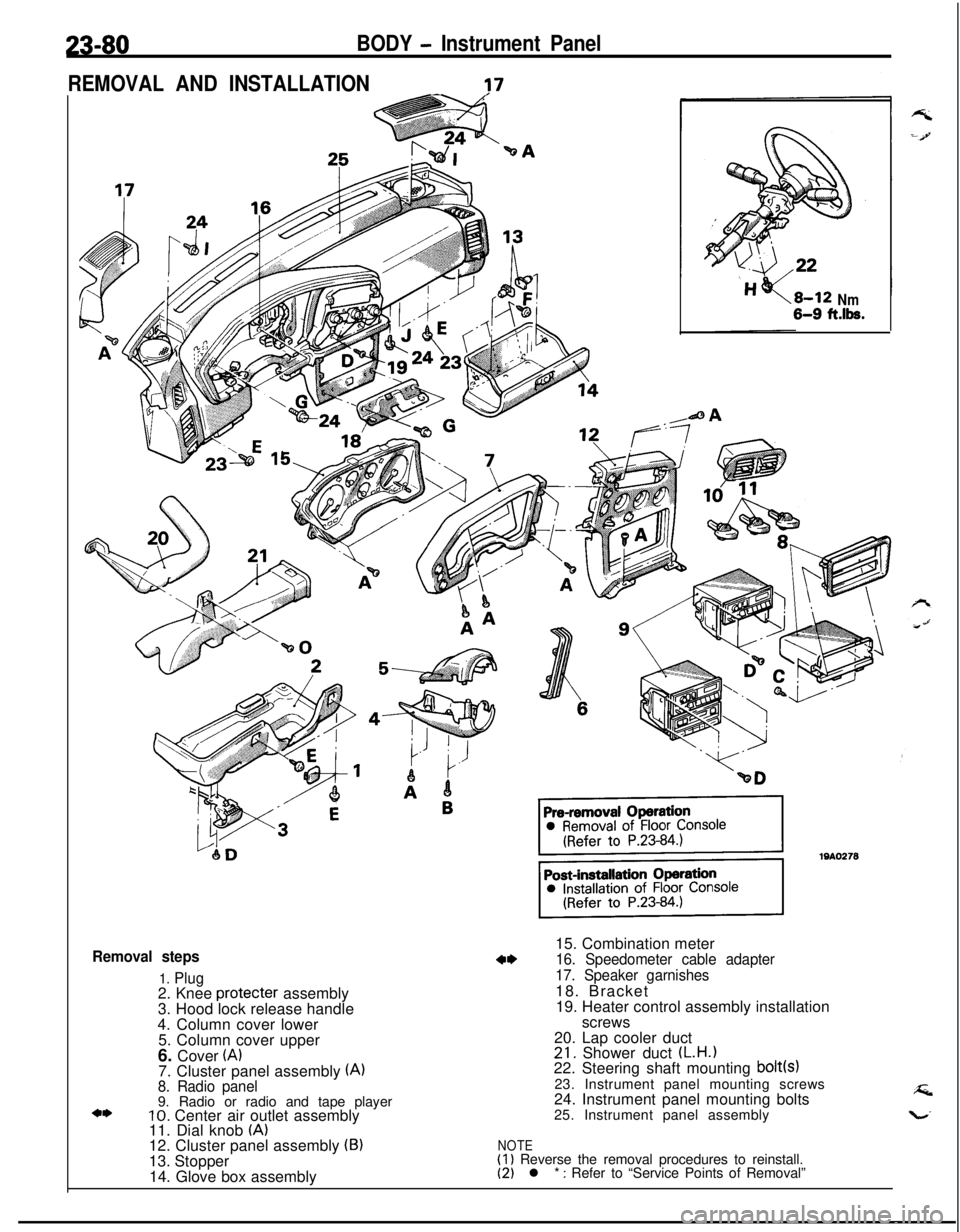
Removal steps
1. Plug2. Knee protecter assembly
3. Hood lock release handle
4. Column cover lower
5. Column cover upper
6. Cover
(A)7. Cluster panel assembly (A)8. Radio panel9. Radio or radio and tape player
10. Center air outlet assembly
11. Dial knob (A)12. Cluster panel assembly (B)13. Stopper
14. Glove box assembly
Nm6-9 ft.lk.15. Combination meter
16. Speedometer cable adapter
17. Speaker garnishes18. Bracket
19. Heater control assembly installation
screws
20. Lap cooler duct
21. Shower duct (L.H.122. Steering shaft mounting bolt(s)23. Instrument panel mounting screws
24. Instrument panel mounting bolts
25. Instrument panel assembly
NOTE(1) Reverse the removal procedures to reinstall.(2) l * : Refer to “Service Points of Removal”
24-26HEATERS AND AIR CONDITIONING - Heater Control AssemblyHEATER CONTROL ASSEMBLY
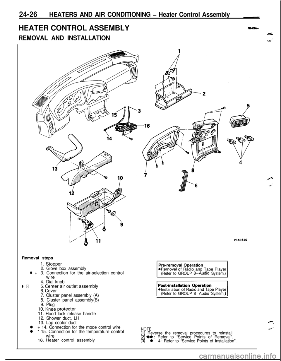
REMOVAL AND INSTALLATIONRemoval steps
1. Stopper2. Glove box assemblyl +3. Connection for the air-selection controlwire
4. Dial knob
l *;: CI.Z;Er air outlet assembly
7. Cluster panel assembly (A)
8. Cluster panel assembly(B)
9. Plug
10. Knee protecter11. Hood lock release handle
12. Shower duct, LH
13. Lap cooler duct
l + 14. Connection for the mode control wire
l * 15. Connection for the temperature controlwire
16. Heater control assembly4
6
2OAO430Pre-removal Operation
@Removal of Radio and Tape Player(Refer to GROUP 8-Audio System.)
(Refer to GROUP
8-Audio System.)
NOTE(1) Reverse the removal procedures to reinstall.(2) 4e : Refer to “Service Points of Removal”.(3) l 4 : Refer to “Service Points of Installation”.
24-30HEATERS AND AIR CONDITIONING - Air Conditioner SwitchAIR CONDITIONER SWITCH
REMOVAL AND--N24OA..INSTALLATION
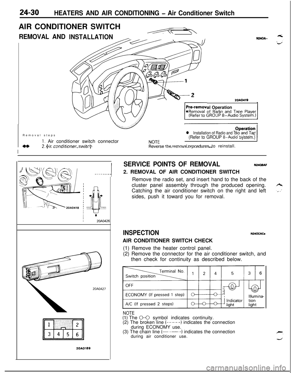
-2OAO419al Operationof
R;tdio and TanePlaver@Removal -..--._ _.-.-, -Removal steps
I. Air conditioner switch connectorCL7 Air rnnditinner switch
l Installation of Radio and Tape Player(Refer to GROUP 8-Audio System.)
NOTEOperation /Reverse
removal orocedures to reinstall.
I
77-. , .,a -.,a ,-,..-,.-. -.....,. ,.._._.__ _..- .-...-.-.r----- --
-----A
20A0427
20A0199
SERVICE POINTS OF REMOVALN24QBAF2. REMOVAL OF AIR CONDITIONER SWITCH
Remove the radio set, and insert hand to the back of the
cluster panel assembly through the produced opening.
Catching the air conditioner switch on the right and left
sides, push it toward you for removal.
INSPECTIONN24OCACaAIR CONDITIONER SWITCH CHECK
(1) Remove the heater control panel.
(2) Remove the connector for the air conditioner switch, and
then check for continuity as described below.
NOTE(1) The 0-0 symbol indicates continuity.
(2) The broken line (-----) indicates the connection
during ECONOMY use.
(3) The chain line
(- -----) indicates the connection
during air conditioner use.


