alternator MITSUBISHI ECLIPSE 1991 Service Manual
[x] Cancel search | Manufacturer: MITSUBISHI, Model Year: 1991, Model line: ECLIPSE, Model: MITSUBISHI ECLIPSE 1991Pages: 1216, PDF Size: 67.42 MB
Page 35 of 1216
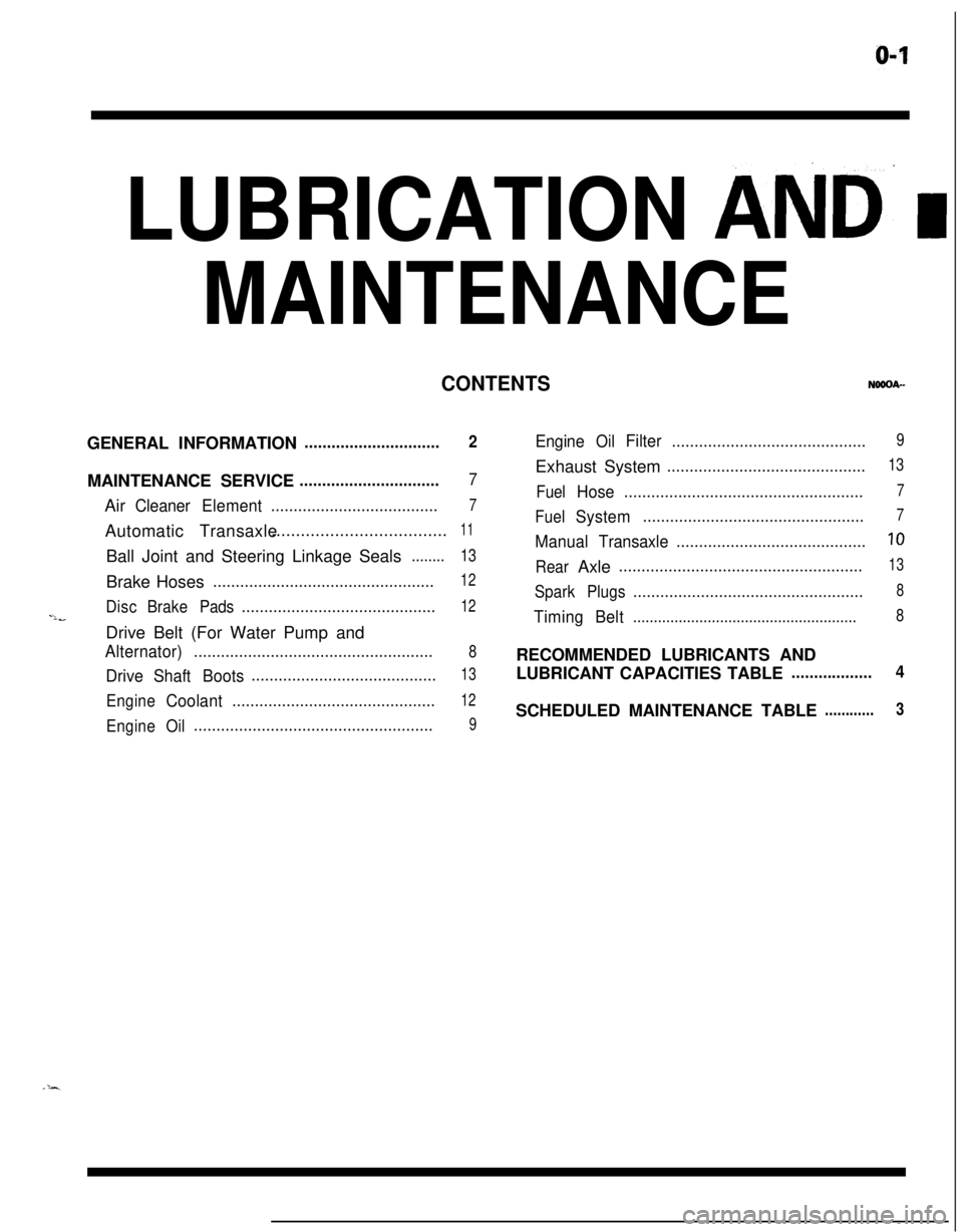
LUBRICATION AND’ I
MAINTENANCE
CONTENTSGENERAL INFORMATION
..............................2MAINTENANCE SERVICE
...............................7Air
CleanerElement.....................................7Automatic Transaxle....................................
11Ball Joint and Steering Linkage Seals
........13Brake Hoses
.................................................12
DiscBrakePads...........................................12-lbDrive Belt (For Water Pump and
Alternator).....................................................8
DriveShaftBoots.........................................13
EngineCoolant.............................................12
EngineOil.....................................................9
EngineOilFilter...........................................9Exhaust System
............................................13
FuelHose.....................................................7
FuelSystem.................................................7
ManualTransaxle..........................................10
RearAxle......................................................13
SparkPlugs...................................................8
TimingBelt......................................................8RECOMMENDED LUBRICANTS AND
LUBRICANT CAPACITIES TABLE
..................4SCHEDULED MAINTENANCE TABLE
............3
Page 37 of 1216
LUBRICATION AND MAINTENANCE - Scheduled MaintenanCe Table. &3
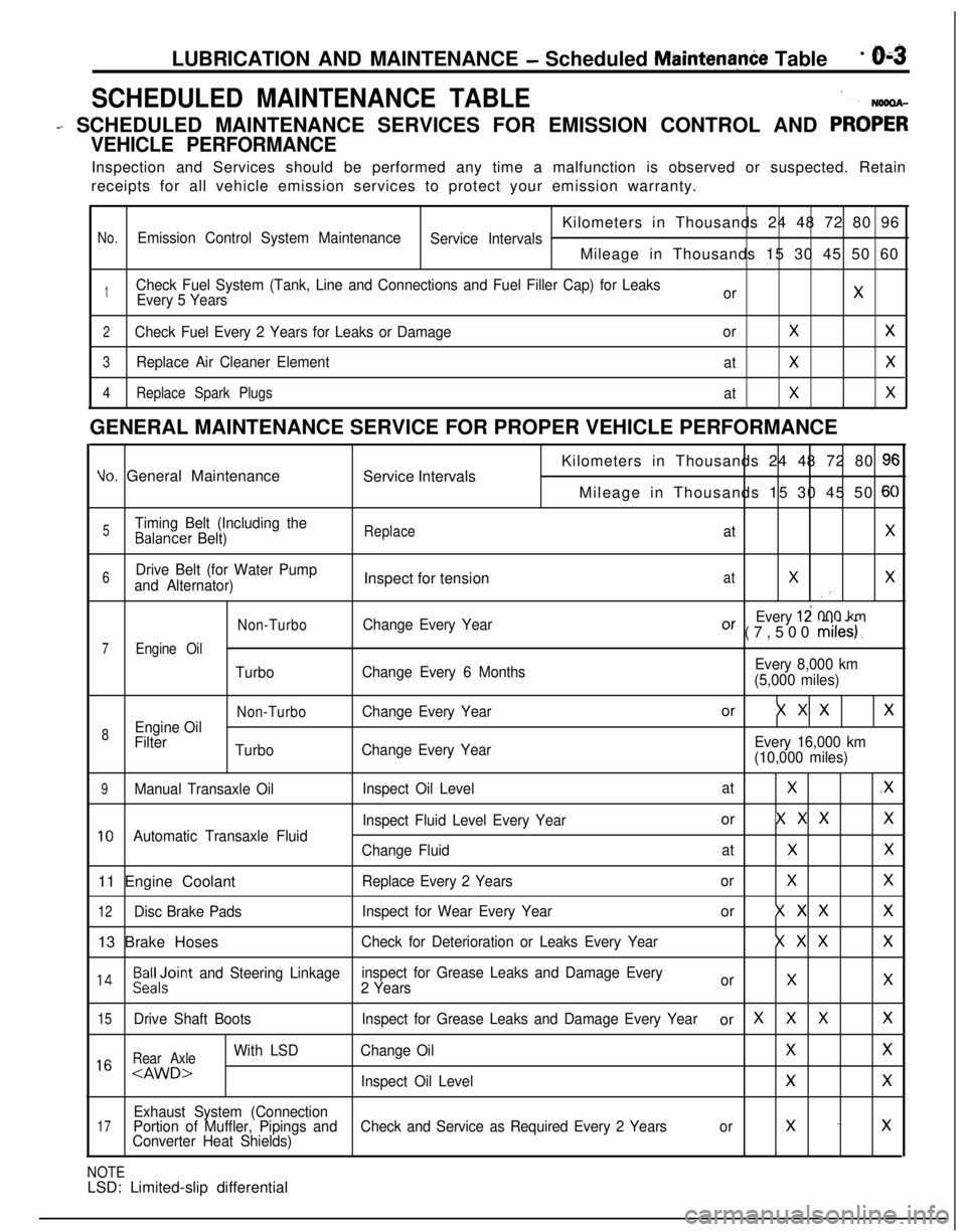
SCHEDULED MAINTENANCE TABLE1
- SCHEDULED MAINTENANCE SERVICES FOR EMISSION CONTROL AND PRO;;
VEHICLE PERFORMANCEInspection and Services should be performed any time a malfunction is observed or suspected. Retain
receipts for all vehicle emission services to protect your emission warranty.
Kilometers in Thousands 24 48 72 80 96
No.Emission Control System Maintenance
Service IntervalsMileage in Thousands 15 30 45 50 60
1Check Fuel System (Tank, Line and Connections and Fuel Filler Cap) for Leaks
Every 5 YearsorX
2Check Fuel Every 2 Years for Leaks or DamageorXX
3Replace Air Cleaner Element
atXX
4Replace Spark Plugs
atXXGENERAL MAINTENANCE SERVICE FOR PROPER VEHICLE PERFORMANCE
Yo. General Maintenance
Service IntervalsKilometers in Thousands 24 48 72 80 9cMileage in Thousands 15 30 45 50
6C
5Timing Belt (Including theBalancer Belt)ReplaceatX
6Drive Belt (for Water Pump
and Alternator)Inspect for tensionatXX.’
Non-TurboChange Every YearEvery 12 000 kmOr (7,500 miles).
7Engine Oil
TurboChange Every 6 MonthsEvery 8,000 km
(5,000 miles)
Non-TurboChange Every Yearor X X XX
8Engine Oil
Filter
TurboChange Every YearEvery 16,000 km
(10,000 miles)
9Manual Transaxle OilInspect Oil LevelatX.X
Inspect Fluid Level Every Yearor X X XX
10Automatic Transaxle Fluid
Change FluidatXX11 Engine Coolant
Replace Every 2 YearsorXX
12Disc Brake PadsInspect for Wear Every Yearor X X XX13 Brake Hoses
Check for Deterioration or Leaks Every YearX X XX
l 4Beiloint and Steering Linkageinspect for Grease Leaks and Damage Every
2 YearsorXX
15Drive Shaft BootsInspect for Grease Leaks and Damage Every Yearor XXXX
Rear Axle
With LSDChange OilXX1 6
Exhaust System (Connection17Portion of Muffler, Pipings andCheck and Service as Required Every 2 Yearsorx -xConverter Heat Shields)
NOTELSD: Limited-slip differential
Page 42 of 1216
O-8LUBRICATION AND MAINTENANCE - Maintenance Service
0-L
I-TOlLO182
-
, ,6COOO9
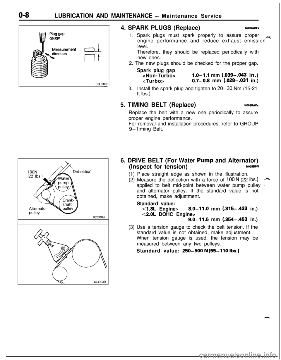
u6COO394. SPARK PLUGS (Replace)
NOOSAOFa1. Spark plugs must spark properly to assure proper
~engine performance and reduce exhaust emission
level.Therefore, they should be replaced periodically with
new ones.
2. The new plugs should be checked for the proper gap.
Spark plug gap
1.0-1.1 mm (.039-.043 in.)
0.7-0.8 mm (.028-.031 in.)
3.Install the spark plug and tighten to 20-30 Nm (15-21
ft.lbs.).5. TIMING BELT (Replace)
NOOSBACaReplace the belt with a new one periodically to assure
proper engine performance.
For removal and installation procedures, refer to GROUP
g-Timing Belt.
6. DRIVE BELT (For Water
Pump and Alternator)
(Inspect for tension)
NOOSSBN(1) Place straight edge as shown in the illustration.
(2) Measure the deflection with a force of
100 N (22 Ibs.)rzapplied to belt mid-point between water pump pulley
-and alternator pulley. If the standard value is not
obtained, make adjustment.
Standard value:
<1.8L Engine>8.0-11.0 mm (.315-A33 in.)
<2.0L DOHC Engine>
9.0-11.5 mm (.354-.453 in.)
(3) Use a tension gauge to check the belt tension. If the
standard value is not obtained, make adjustment.
When tension gauge is used, the tension may be
measured between any two pulleys.
Standard value:
250-500 N (55-110 Ibs.)
Page 249 of 1216
7-l
COOLING
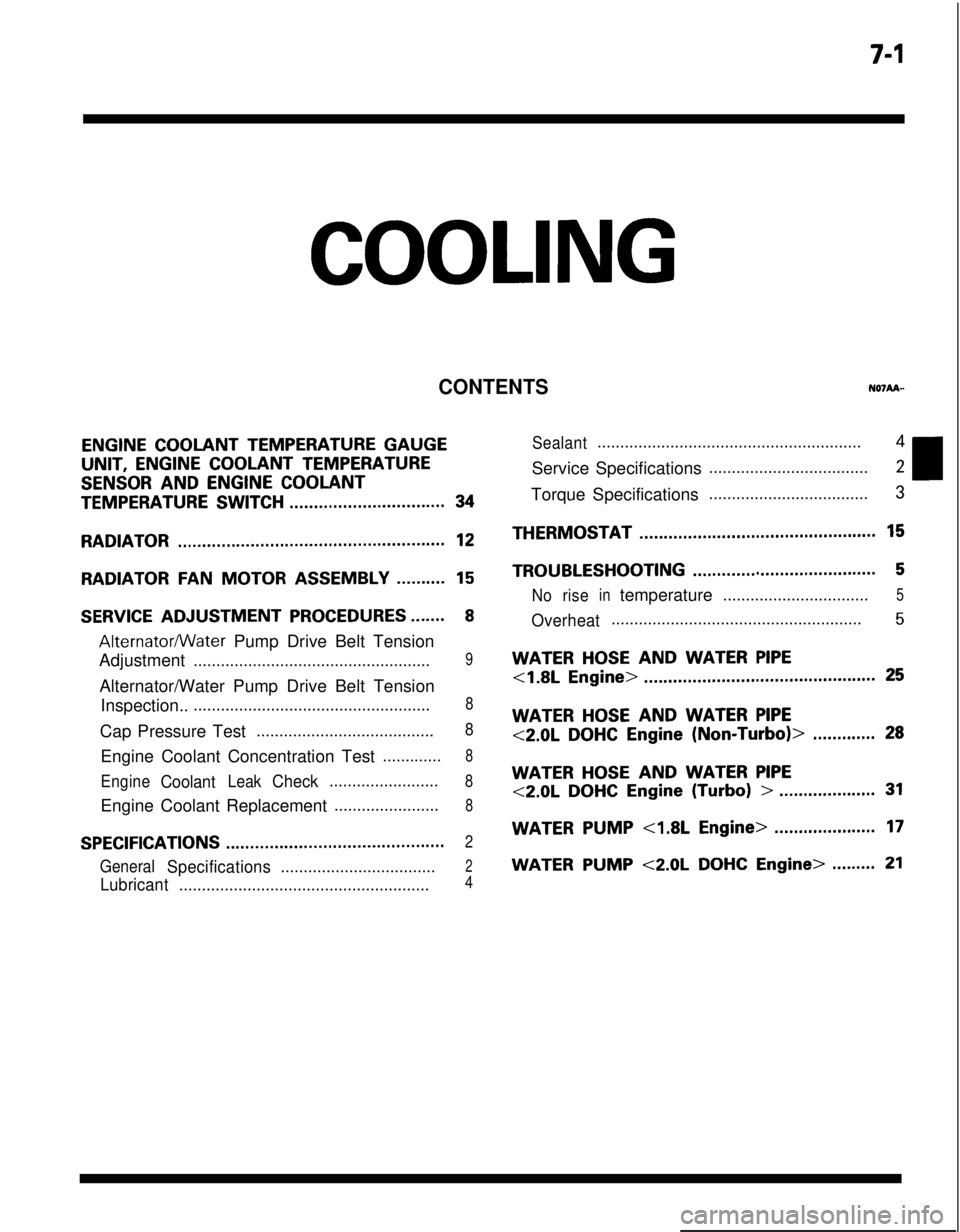
CONTENTS
ENGINE COOLANT TEMPERATURE GAUGEUNIT,
ENGINE COOLANT TEMPERATURE
SENSOR AND ENGINE COOLANT
TEMPERATURE SWITCH................................34
RADIATOR.......................................................12
RADIATORFANMOTOR ASSEMBLY..........15
SERVICE ADJUSTMENT PROCEDURES.......8
Alternatormater Pump Drive Belt Tension
Adjustment
....................................................9Alternator/Water Pump Drive Belt Tension
Inspection..
....................................................8Cap Pressure Test
.......................................8Engine Coolant Concentration Test
.............8
EngineCoolantLeakCheck........................8Engine Coolant Replacement
.......................8
SPECIFICATIONS.............................................2
GeneralSpecifications..................................2
Lubricant.......................................................4
Sealant..........................................................4Service Specifications
...................................2Torque Specifications
...................................3THERMOSTAT
.................................................15
TROUBLESHOOTING......................................5
Noriseintemperature................................5
Overheat.......................................................5
WATER HOSE AND WATER PIPE
<1.8L Engine>................................................25
WATER HOSE AND WATER PIPE
<2.0LDOHCEngine(Non-Turbo)>.............28
WATER HOSE AND WATER PIPE
<2.0LDOHCEngine(Turbo)>....................31
WATERPUMP<1.8LEngine>.....................17
WATER PUMP <2.0L DOHC Engine>.........21
Page 256 of 1216
7-8COOLING - Service Adjustment Procedures
04DooE
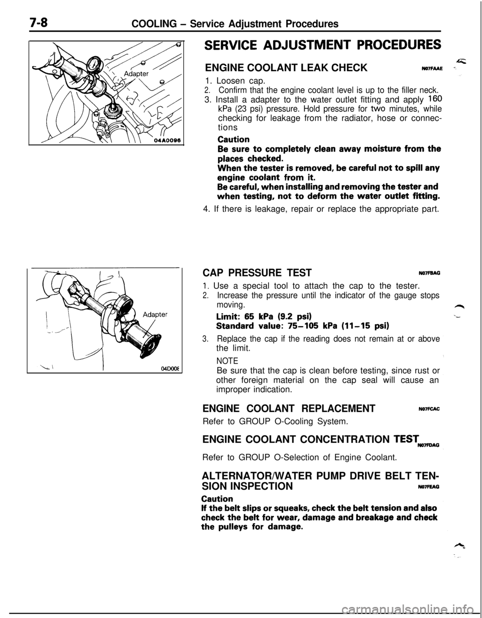
SERVICE ADJUSTMENT PROCEDURESENGINE COOLANT LEAK CHECK
NO7FAAE1. Loosen cap.
2.Confirm that the engine coolant level is up to the filler neck.3. Install a adapter to the water outlet fitting and apply
160
kPa (23 psi) pressure. Hold pressure for tvvo minutes, whilechecking for leakage from the radiator, hose or connec-
tionsCaution
Be sure to completely clean away moisture from the
places checked.When the tester
is removed, be careful not to spill anyengine coolant from
it.
Be careful, when installing and removing the tester andwhen testing, not
to deform the water outlet fitting.
4. If there is leakage, repair or replace the appropriate part.
CAP PRESSURE TESTNO’IFBAG
1. Use a special tool to attach the cap to the tester.
2.Increase the pressure until the indicator of the gauge stops
moving.Limit:
65 kPa (9.2 psi)Standard value:
75-105 kPa (11-15 psi)
3.Replace the cap if the reading does not remain at or abovethe limit.
NOTEBe sure that the cap is clean before testing, since rust or
other foreign material on the cap seal will cause an
improper indication.
ENGINE COOLANT REPLACEMENTRefer to GROUP O-Cooling System.NO’IFCACENGINE COOLANT CONCENTRATION
TESTmAGRefer to GROUP O-Selection of Engine Coolant.
ALTERNATOR/WATER PUMP DRIVE BELT TEN-
SION INSPECTION
NO7FEAGCaution
If the belt slips or squeaks, check the belt tension and also
check the belt for wear, damage and breakage and checkthe
pulleys for damage.
Page 257 of 1216
COOLING - Service Adjustment Procedures7-9Alterhatorpulley
6COOOO9
Spindle
l-
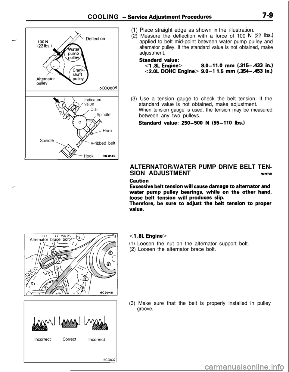
(1) Place straight edge as shown in the illustration.(2) Measure the deflection with a force of 100
N(22lb4applied to belt mid-point between water pump pulley and
alternator pulley. If the standard value is not obtained, make
adjustment.Standard
value:
8.0-11.0 mm (.315-433 in.)
<2.0L DOHC Engine> 9.0-I 1.5 mm (.354-.453 in.)(3) Use a tension gauge to check the belt tension. If the
standard value is not obtained, make adjustment.
When tension gauge is used, the tension may be measuredbetween any two pulleys.Standard
value: 250-500 N (55-110 Ibs.)
IncorrectCorrectIncorrect
6COO37-ALTERNATOR/WATER PUMP DRIVE BELT TEN-
SION ADJUSTMENT
ruo7FFAl
Caution
Excessive belt tension will cause damage to alternator and
water pump pulley bearings, while on the other hand,
loose belt tension will produces slip.
Therefore, be sure to adjust the belt tension to proper
value.
(1) Loosen the nut on the alternator support bolt.
(2) Loosen the alternator brace bolt.
(3) Make sure that the belt is properly installed in pulley
groove.
Page 258 of 1216
COOLING - Service Adjustment Procedures100N
(22 Ibs.)
DeflecAlternator
ypulley
:tion
6COOOO9
Spindle ,
HookOlLO149
IncorrectCorrectIncorrect
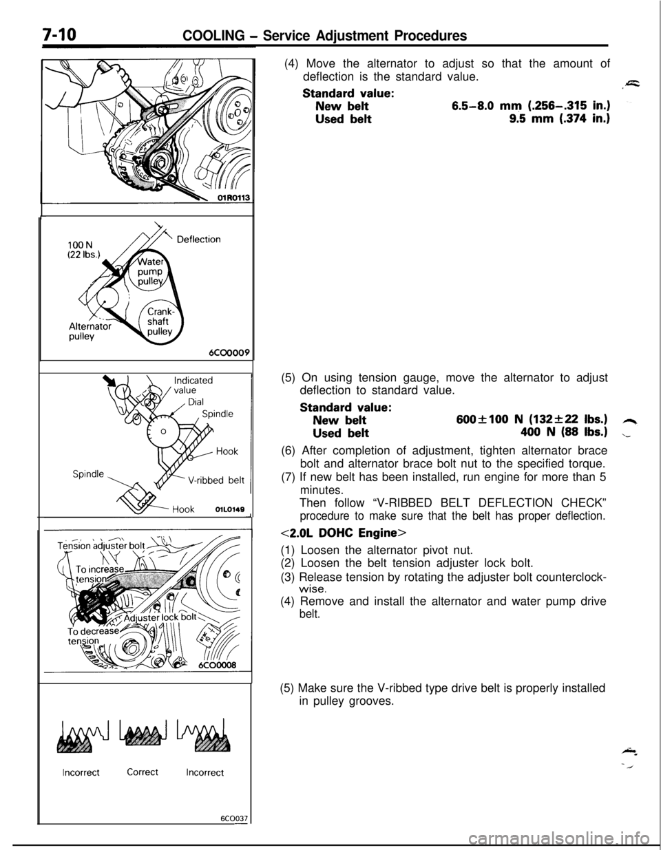
6COO37-(4) Move the alternator to adjust so that the amount of
deflection is the standard value.Standard
value:
New belt6.5-8.0 mm (.256-.315 in.)
Used belt9.5 mm (.374 in.)(5) On using tension gauge, move the alternator to adjust
deflection to standard value.Standard
value:
New belt600flOO N (132+22 Ibs.)
Used belt400 N (88 Ibs.)(6) After completion of adjustment, tighten alternator brace
bolt and alternator brace bolt nut to the specified torque.
(7) If new belt has been installed, run engine for more than 5
minutes.Then follow “V-RIBBED BELT DEFLECTION CHECK”
procedure to make sure that the belt has proper deflection.
<2.0L DOHC Engine>
(1) Loosen the alternator pivot nut.
(2) Loosen the belt tension adjuster lock bolt.
(3) Release tension by rotating the adjuster bolt counterclock-
wise.(4) Remove and install the alternator and water pump drive
belt.(5) Make sure the V-ribbed type drive belt is properly installed
in pulley grooves.
Page 259 of 1216
COOLING - Service Adjustment Procedures7-m
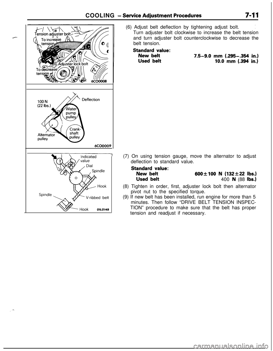
1(6) Adjust belt deflection by tightening adjust bolt.
:Turn adjuster bolt clockwise to increase the belt tension
and turn adjuster bolt counterclockwise to decrease the
belt tension.
Standard value:
New belt7.5-9.0 mm (.295-.354 in.)
Used belt10.0 mm (.394 in.)(7) On using tension gauge, move the alternator to adjust
deflection to standard value.
Standard value:
New belt600+100 N (132f22 Ibs.)
Used belt
400 N (88 Ibs.)(8) Tighten in order, first, adjuster lock bolt then alternator
pivot nut to the specified torque.
(9) If new belt has been installed, run engine for more than 5
minutes. Then follow “DRIVE BELT TENSION INSPEC-
TION” procedure to make sure that the belt has proper
tension and readjust if necessary.
Page 266 of 1216
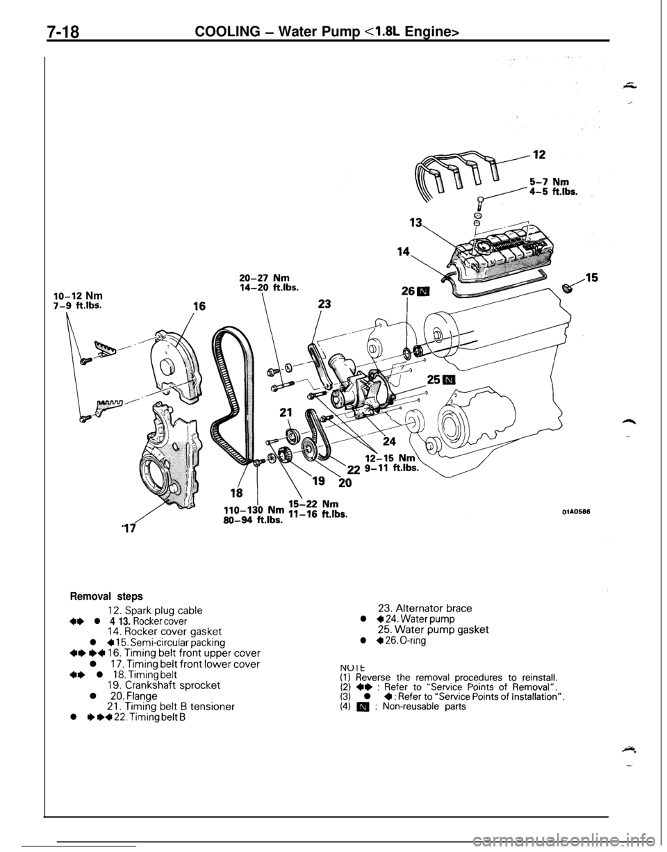
7-18COOLING - Water Pump <1.8L Engine>
lo-12 Nm7-9 ft.lbs.OlA05813
17
Removal steps
12. Spark plug cable+e l 4 13. Rocker cover14. Rocker cover gasket
l + 15. Semi-circular packing~~ e+ 16. Timing belt front upper coverl
17. Timing belt front lower cover+e l 18. Timing belt19. Crankshaft sprocketl 20. Flange21.
Timing belt B tensionerl I) ~~ 22. Timing belt B23.
Alternator bracel + 24. Water pump25.
Water pump gasketl + 26. O-ring
NUlt(I) Reverse the removal procedures to reinstall.(2) ** : Refer to “Service Points of Removal”.(3) l 4 : Refer to “Service Points of Installation”.(4) m : Non-reusable parts
Page 270 of 1216
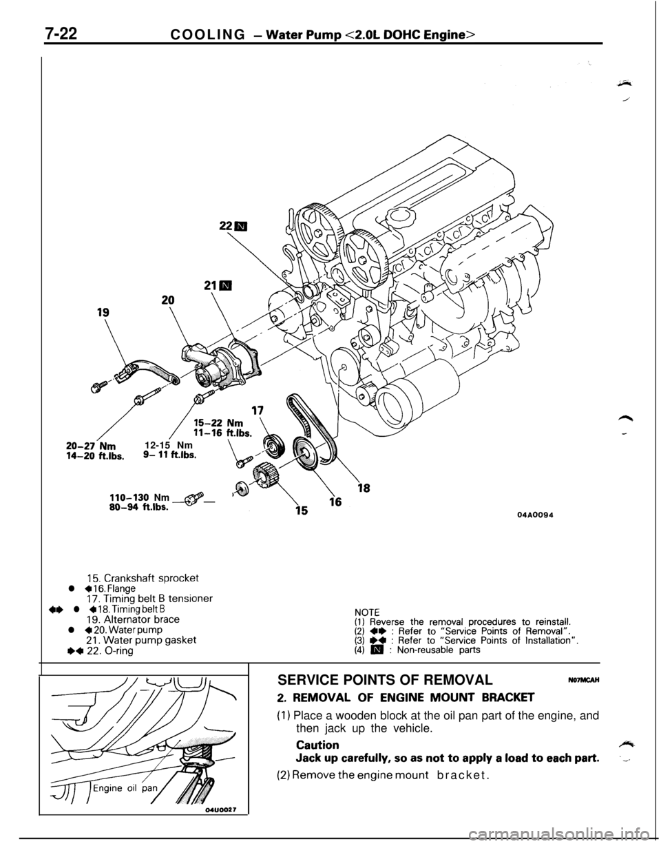
7-22COOLING - Water Pump <2.0L DOHC Engine>
20-27-Nm12-15 Nm14-20 ft.lbs.9- 11 ftlbs.\,/”
110-130 Nm@80-94 ftlbs. -04A0094
15. Crankshaft sprocketl a 16. Flange17. Timing belt B tensioner4e l + 18. Timing belt B19. Alternator bracel 4 20. Water pump21. Water pump gasketI)* 22. O-ring
NOTE(I) Reverse the removal procedures to reinstall.(2) 4* : Refer to “Service Points of Removal”.(3) ** : Refer to “Service Points of Installation”.(4) m : Non-reusable partsSERVICE POINTS OF REMOVAL
NO’IMCAH
2. REMOVAL OF ENGINE MOUNT BRACKET
(1) Place a wooden block at the oil pan part of the engine, and
then jack up the vehicle.
Cautioncylb
Jack up carefully, so as not to apply a load to each part..__
(2) Remove the engine mount bracket.