ESP MITSUBISHI ECLIPSE 1991 User Guide
[x] Cancel search | Manufacturer: MITSUBISHI, Model Year: 1991, Model line: ECLIPSE, Model: MITSUBISHI ECLIPSE 1991Pages: 1216, PDF Size: 67.42 MB
Page 103 of 1216
3-1
REAR AXLE
CONTENTSAXLE SHAFT
...................................................10
DIFFERENTIAL CARRIER................................19DRIVE SHAFT
..................................................13SERVICE ADJUSTMENT PROCEDURES..
.....8
GearOilLevelCheck...................................8
LimitedSlipDifferentialCheck....................9
..Rear Axle Total Backlash Check.................8Rear Wheel Bearing End Play Check
.........
8Rear Wheel Bearing Rotation Sliding
ResistanceCheck.........................................9
SPECIALTOOLS.............................................4
SPECIFICATIONS.............................................
2
GeneralSpecifications..................................2
Lubricants......................................................3Sealants and Adhesives...............................
3Service
Specifications...................................2TorqueSpecifications...................................
3
TROUBLESHOOTING......................................6Axle Shaft
Grease leakageNoise while wheels are rotatingDifferential (Conventional Differential)
Bearing noise while driving or coasting
Constant noise
Gear noise while coasting
Gear noise while driving
HeatNoise while turning
Oil leakage
Differential (Limited Slip Differential)
Abnormal noise during driving or
gear changing
Abnormal noise when cornering
Break down
Gear noise
Gear oil leakage
SeizureThe limited slip differential does
not function
Drive Shaft
Noise
Page 119 of 1216
REAR AXLE - Drive Shaft3-1711
ES07
.-
llYO97
8.J: bootBoot bands
D.O.J. bootllW592
11KOOOSERVICE POINTS OF DISASSEMBLY
NO3JEAC6. REMOVAL OF SNAP RING/8.
BALLS/S. D.O.J. INNER
RACE/IO. D.O.J. CAGE
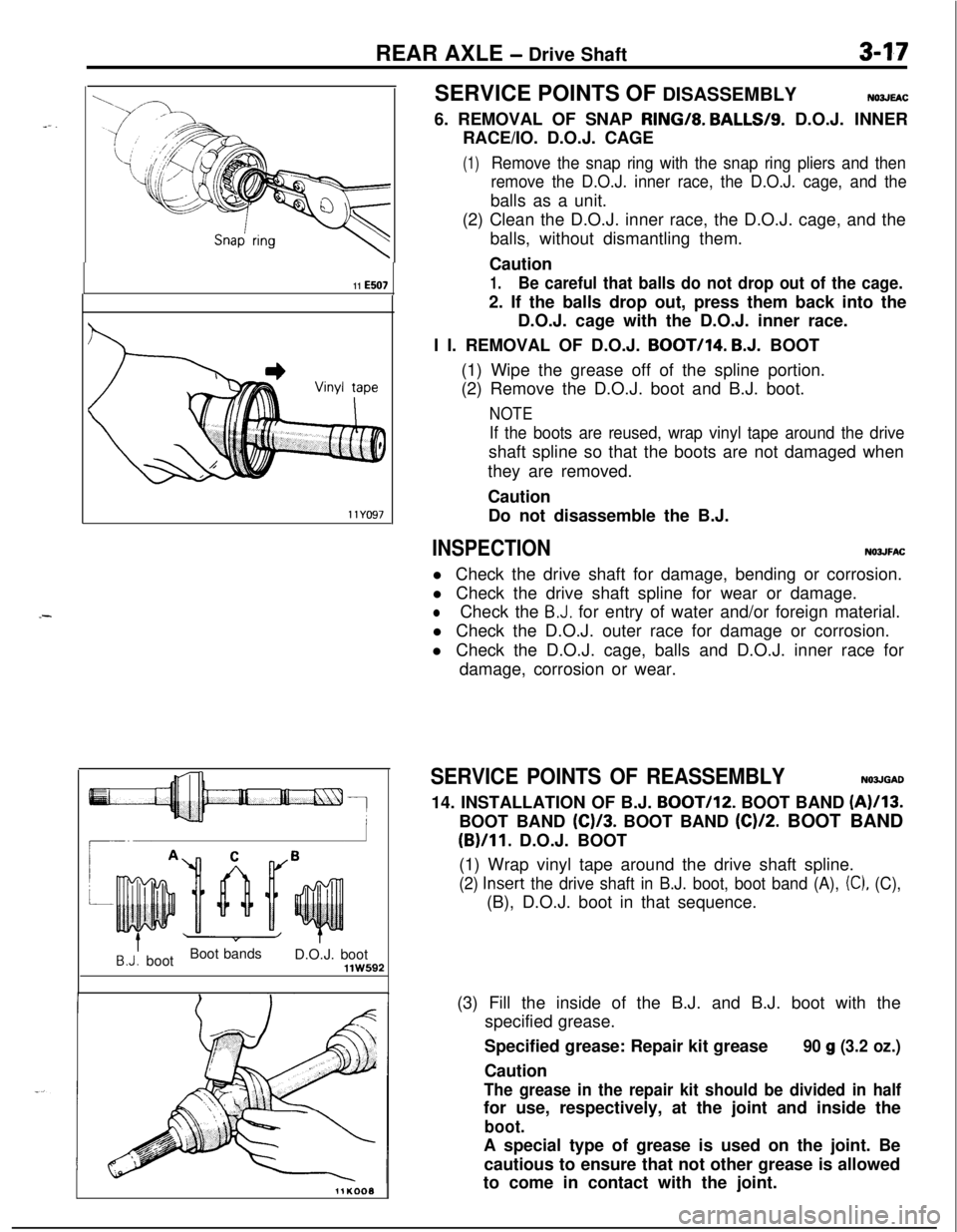
(1)Remove the snap ring with the snap ring pliers and then
remove the D.O.J. inner race, the D.O.J. cage, and theballs as a unit.
(2) Clean the D.O.J. inner race, the D.O.J. cage, and the
balls, without dismantling them.
Caution
1.Be careful that balls do not drop out of the cage.2. If the balls drop out, press them back into the
D.O.J. cage with the D.O.J. inner race.
I I. REMOVAL OF D.O.J.
BOOT/I4. B.J. BOOT
(1) Wipe the grease off of the spline portion.
(2) Remove the D.O.J. boot and B.J. boot.
NOTE
If the boots are reused, wrap vinyl tape around the driveshaft spline so that the boots are not damaged when
they are removed.
Caution
Do not disassemble the B.J.
INSPECTIONNOJJFACl Check the drive shaft for damage, bending or corrosion.
l Check the drive shaft spline for wear or damage.
lCheck the B.J. for entry of water and/or foreign material.
l Check the D.O.J. outer race for damage or corrosion.
l Check the D.O.J. cage, balls and D.O.J. inner race for
damage, corrosion or wear.
SERVICE POINTS OF REASSEMBLYN03JGAD14. INSTALLATION OF B.J.
BOOT/I*. BOOT BAND (A)/I3.BOOT BAND
(C)/3. BOOT BAND (C)/2. BOOT BAND
(B)/II. D.O.J. BOOT
(1) Wrap vinyl tape around the drive shaft spline.
(2) Insert the drive shaft in B.J. boot, boot band (A), (C), (C),(B), D.O.J. boot in that sequence.
(3) Fill the inside of the B.J. and B.J. boot with the
specified grease.
Specified grease: Repair kit grease
Caution
90 g (3.2 oz.)
The grease in the repair kit should be divided in halffor use, respectively, at the joint and inside the
boot.A special type of grease is used on the joint. Be
cautious to ensure that not other grease is allowed
to come in contact with the joint.
Page 120 of 1216
3-18REAR AXLE - Drive Shaft
ring
\
Inner race
1180116
llE507
7.(4) Secure the B.J. boot with boot bands (A) and
(C) to the
drive shaft and B.J.
Caution
-Ensure that the B.J. is at a zero angle with the drive
shaft to ensure the boot contains the specified
amount of air.
INSTALLATION OF D.O.J. INNER RACE, CAGE AND
BALL ASSEMBLY
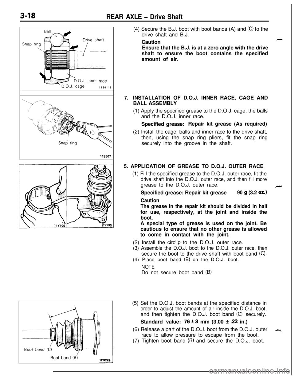
(1) Apply the specified grease to the D.O.J. cage, the balls
and the D.O.J. inner race.
Specified grease:Repair kit grease (As required)
(2) Install the cage, balls and inner race to the drive shaft,
then, using the snap ring pliers, fit the snap ring
securely into the groove in the shaft.
5. APPLICATION OF GREASE TO D.O.J. OUTER RACE
(1) Fill the specified grease to the D.O.J. outer race, fit the
drive shaft into the D.O.J. outer race, and then fill moregrease to the D.O.J. outer race.
Specified grease: Repair kit grease
90 g (3.2 oz.)
Caution
The grease in the repair kit should be divided in halffor use, respectively, at the joint and inside the
boot.A special type of grease is used on the joint. Be
cautious to ensure that no other grease is allowed
to come in contact with the joint.
(2) Install the
circlip to the D.O.J. outer race.
(3) Assemble the D.O.J. boot to the D.O.J. outer race, thensecure the boot to the drive shaft with boot band
(C).(4) Place boot band
(B) on the D.O.J. boot.
NOTEDo not secure boot band
(9)(5) Set the D.O.J. boot bands at the specified distance in
order to adjust the amount of air inside the D.O.J. boot,and then tighten the D.O.J. boot band
(C) securely.
Standard value: 76+-3 mm (3.00
& .23 in.)
(6) Release a part of the D.O.J. boot from the D.O.J. outer
--race to allow pressure to escape from the boot.
(7) Tighten boot band
(9) and secure the D.O.J. boot.
Boot band
(8’)
Page 127 of 1216
REAR AXLE -Differential Carrier3-25
Mating marks
llD237
llY175
llY17619. REMOVAL OF DRIVE PINION
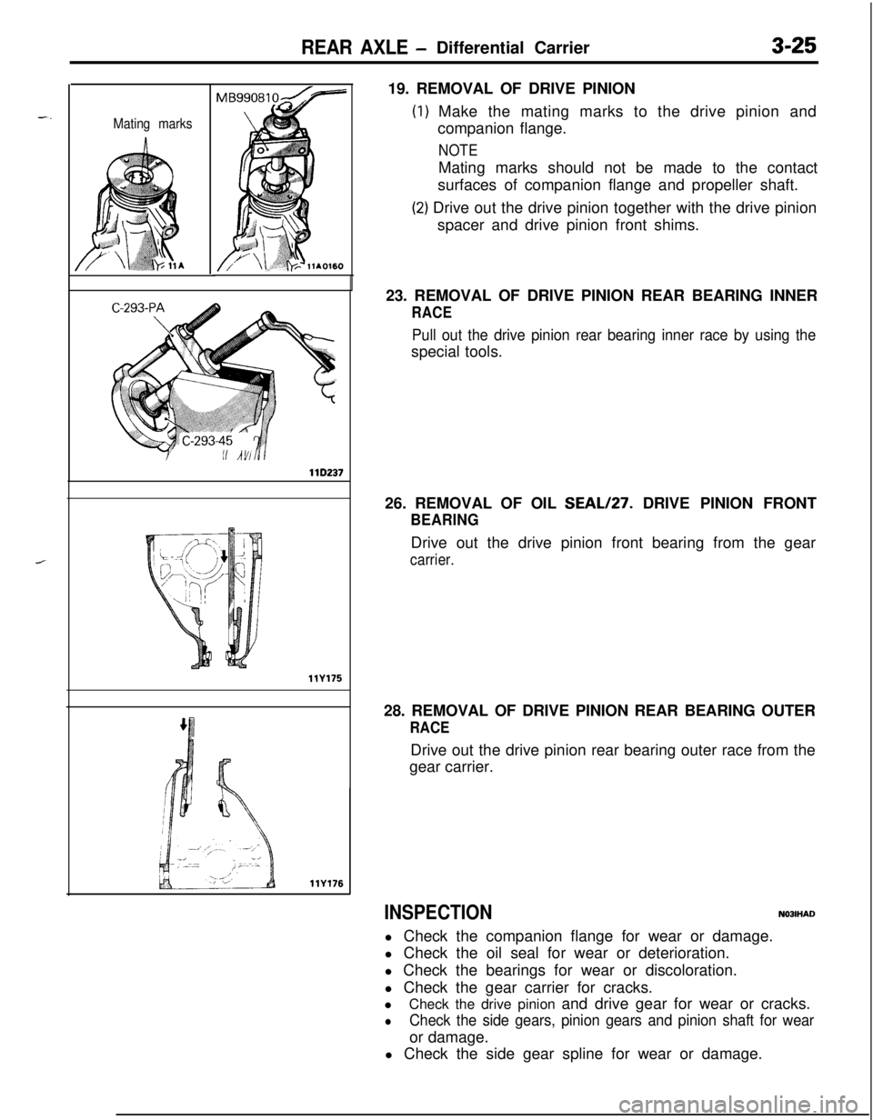
) Make the mating marks to the drive pinion and
companion flange.
NOTEMating marks should not be made to the contact
surfaces of companion flange and propeller shaft.
!) Drive out the drive pinion together with the drive pinion
spacer and drive pinion front shims.
23. REMOVAL OF DRIVE PINION REAR BEARING INNER
RACE
Pull out the drive pinion rear bearing inner race by using thespecial tools.
26. REMOVAL OF OIL SEAL/27. DRIVE PINION FRONT
BEARINGDrive out the drive pinion front bearing from the gear
carrier.28. REMOVAL OF DRIVE PINION REAR BEARING OUTER
RACEDrive out the drive pinion rear bearing outer race from the
gear carrier.
INSPECTIONN03lHADl Check the companion flange for wear or damage.
l Check the oil seal for wear or deterioration.
l Check the bearings for wear or discoloration.
l Check the gear carrier for cracks.
lCheck the drive pinion and drive gear for wear or cracks.
lCheck the side gears, pinion gears and pinion shaft for wearor damage.
l Check the side gear spline for wear or damage.
Page 130 of 1216
3-28REAR AXLE - Differential Carrier
Y223
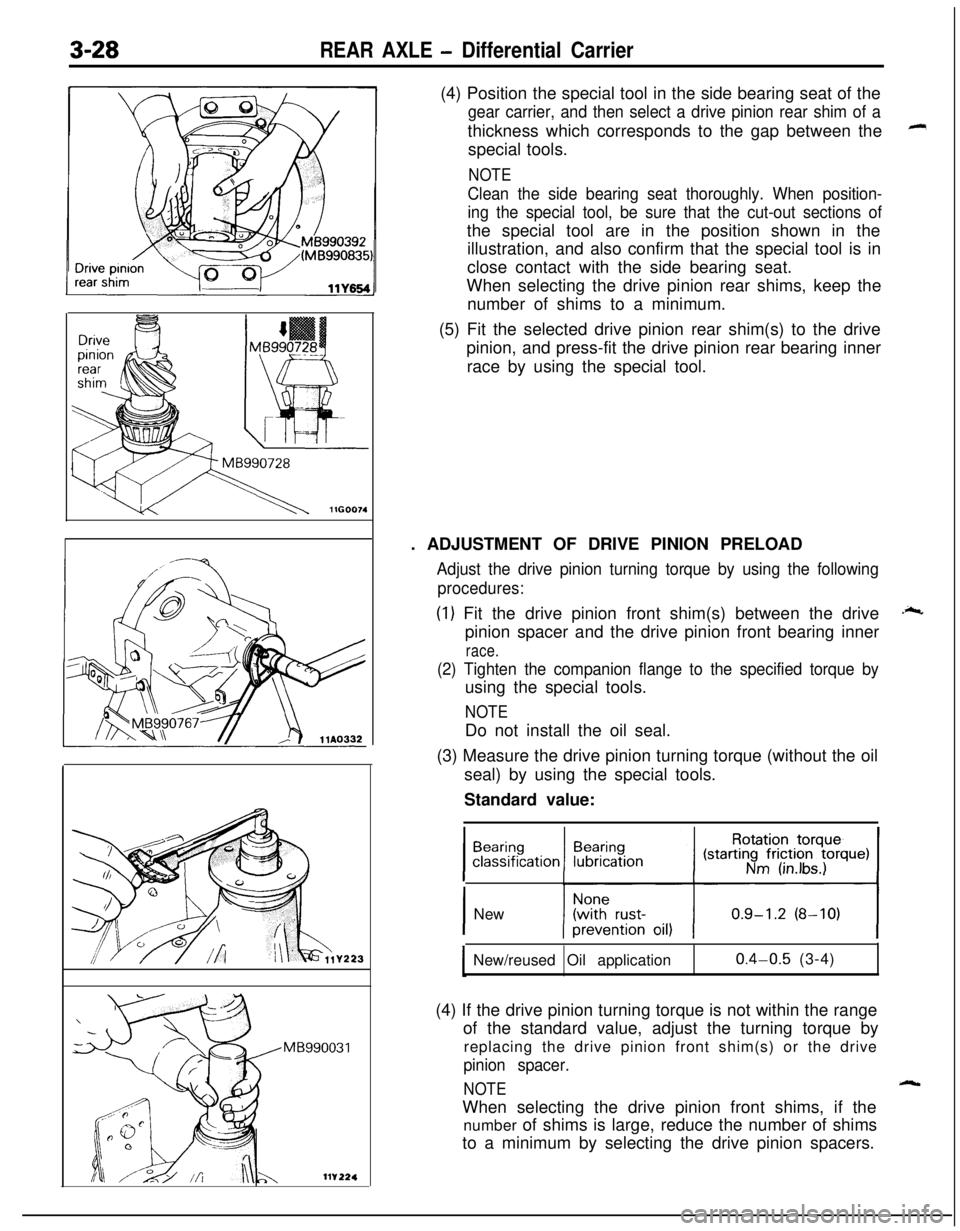
MB990031(4) Position the special tool in the side bearing seat of the
gear carrier, and then select a drive pinion rear shim of athickness which corresponds to the gap between the
special tools.
NOTE
Clean the side bearing seat thoroughly. When position-
ing the special tool, be sure that the cut-out sections ofthe special tool are in the position shown in the
illustration, and also confirm that the special tool is in
close contact with the side bearing seat.
When selecting the drive pinion rear shims, keep the
number of shims to a minimum.
(5) Fit the selected drive pinion rear shim(s) to the drive
pinion, and press-fit the drive pinion rear bearing inner
race by using the special tool.
. ADJUSTMENT OF DRIVE PINION PRELOAD
Adjust the drive pinion turning torque by using the following
procedures:
(1) Fit the drive pinion front shim(s) between the drive
pinion spacer and the drive pinion front bearing inner
race.
(2) Tighten the companion flange to the specified torque byusing the special tools.
NOTEDo not install the oil seal.
(3) Measure the drive pinion turning torque (without the oil
seal) by using the special tools.
Standard value:
21
.;c
1 New
New/reused Oil application
0.4-0.5 (3-4)
(4) If the drive pinion turning torque is not within the range
of the standard value, adjust the turning torque by
replacing the drive pinion front shim(s) or the drive
pinion spacer.
NOTEWhen selecting the drive pinion front shims, if the
number of shims is large, reduce the number of shims
to a minimum by selecting the drive pinion spacers.
Page 133 of 1216
REAR AXLE -Differential Carrier3-31
= Thicknessof the
spacer on one side
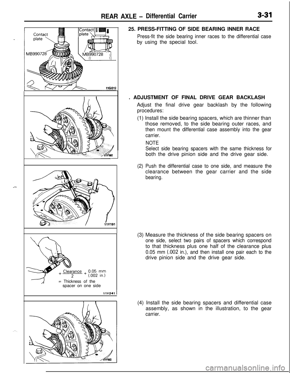
llV241I25. PRESS-FITTING OF SIDE BEARING INNER RACE
Press-fit the side bearing inner races to the differential caseby using the special tool.
. ADJUSTMENT OF FINAL DRIVE GEAR BACKLASH
Adjust the final drive gear backlash by the following
procedures:(1) Install the side bearing spacers, which are thinner than
those removed, to the side bearing outer races, and
then mount the differential case assembly into the gear
carrier.
NOTE
Select side bearing spacers with the same thickness forboth the drive pinion side and the drive gear side.
(2) Push the differential case to one side, and measure theclearance between the gear carrier and the side
bearing.(3) Measure the thickness of the side bearing spacers on
one side, select two pairs of spacers which correspondto that thickness plus one half of the clearance plus
0.05 mm (.002 in.), and then install one pair each to thedrive pinion side and the drive gear side.
(4) Install the side bearing spacers and differential case
assembly, as shown in the illustration, to the gear
carrier.
Page 233 of 1216
CLUTCH - Specifications/Special Tool6-3
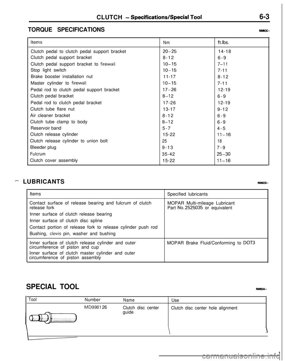
TORQUE SPECIFICATIONSNMCC-Items
Nmftlbs.Clutch pedal to clutch pedal support bracket
20-2514-18
Clutch pedal support bracket
8-12
6-9
Clutch pedal support bracket to firewall
10-157-l 1Stop light switch
10-157-11
Brake booster installation nut
11-17
8-12
Master cylinder to firewall
10-157-11
Pedal rod to clutch pedal support bracket
17-2612-19
Clutch pedal bracket
8-l 26-9
Pedal rod to clutch pedal bracket
17-2612-19
Clutch tube flare nut
13-17
9-12
Air cleaner bracket
8-12
6-9
Clutch tube clamp to body
8-l 26-9
Reservoir band
5-7
4-5
Clutch release cylinder
15-22
11-16Clutch release cylinder to union bolt
2518Bleeder plug
9-13
7-9
Fulcrum35-4225-30Clutch cover assembly
15-22
11-16
- LUBRICANTSNOSCD-Items
Contact surface of release bearing and fulcrum of clutch
release fork
Inner surface of clutch release bearing
Inner surface of clutch disc splineSpecified lubricants
MOPAR Multi-mileage Lubricant
Part
No.2525035 or equivalent
Contact portion of release fork to release cylinder push rod
Bushing,
clevis pin, washer and bushing
Inner surface of clutch release cylinder and outer
circumference of piston and cupMOPAR Brake Fluid/Conforming to
DOT3Inner surface of clutch master cylinder and outer
circumference of piston assembly
SPECIAL TOOL
ToolNumber
MD9981 26
NameUse
Clutch disc center
guideClutch disc center hole alignment
\\
Page 250 of 1216
7-2COOLING - Specifications
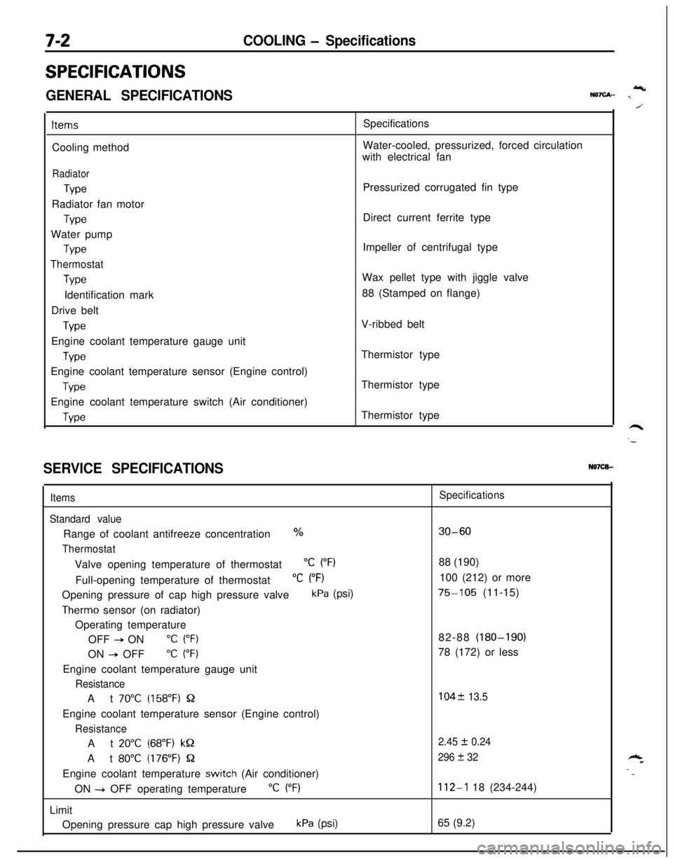
SPECIFICATIONS
GENERAL SPECIFICATIONSIcNQ7cA- I
ItemsCooling method
Radiator
TypeRadiator fan motor
TypeWater pump
Type
Thermostat
TypeIdentification mark
Drive belt
TypeEngine coolant temperature gauge unit
WeEngine coolant temperature sensor (Engine control)
TypeEngine coolant temperature switch (Air conditioner)
WeSpecifications
Water-cooled, pressurized, forced circulation
with electrical fan
Pressurized corrugated fin type
Direct current ferrite type
Impeller of centrifugal type
Wax pellet type with jiggle valve
88 (Stamped on flange)
V-ribbed belt
Thermistor type
Thermistor type
Thermistor type
SERVICE SPECIFICATIONSN07CB.-
Items
Standard valueRange of coolant antifreeze concentration
%
ThermostatValve opening temperature of thermostat
“C (“F)Full-opening temperature of thermostat
“C (“F)Opening pressure of cap high pressure valve
kPa (psi)
Therm0 sensor (on radiator)
Operating temperature
OFF
+ ON“C (“F)ON
--P OFF“C (“F)Engine coolant temperature gauge unit
ResistanceAt
70°C (158°F) QEngine coolant temperature sensor (Engine control)
ResistanceAt
20°C (68°F) kQAt
80°C (176°F) QEngine coolant temperature
switch (Air conditioner)
ON -+ OFF operating temperature
“C (“F)Limit
Opening pressure cap high pressure valve
kPa (psi)
Specifications
30-6088 (190)
100 (212) or more
75-105 (11-15)
82-88 (180-190)
78 (172) or less
104f 13.5
2.45
I!I 0.24
296
+ 32
112-l 18 (234-244)
65 (9.2)
Page 339 of 1216
ENGINE - Cylinder Head and Valve9-55
3EN026
w -w===j=Margin , EN034
Squareness
IFree length
INSPECTION
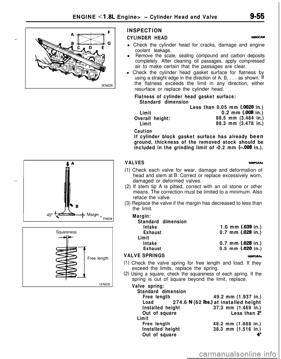
CYLINDER HEADNosocAMl Check the cylinder head for cracks, damage and engine
coolant leakage.l
Remove the scale, sealing compound and carbon deposits
completely. After cleaning oil passages, apply compressedair to make certain that the passages are clear.
l Check the cylinder head gasket surface for flatness by
using a straight edge in the direction of A, B, . . . as shown. Ifthe flatness exceeds the limit in any direction, either
resurface or replace the cylinder head.
Flatness of cylinder head gasket surface:
Standard dimension
Limit
Overall height:
Limit
Caution
Less than 0.05 mm (0020 in.)
0.2 mm (008 in.)
88.5 mm (3.484 in.)
88.3 mm (3.478 in.)
If cylinder block gasket surface has already been
ground, thickness of the removed stock should be
included in the grinding limit of -0.2 mm
(-,008 in.).
VALVESNo9PGMa
(1) Check each valve for wear, damage and deformation of
head and stem at
B. Correct or replace excessively worn,
damaged or deformed valves.
(2) If stem tip A is pitted, correct with an oil stone or other
means. The correction must be limited to a minimum. Also
reface the valve.
(3) Replace the valve if the margin has decreased to less than
the limit.
Margin:
Standard dimension
Intake1.0 mm (.039 in.)
Exhaust0.7 mm (028 in.)
Limit
Intake0.7 mm (.028 in.)
Exhaust0.5 mm LO20 in.)
VALVE SPRINGSNOWGh
(1) Check the valve spring for free length and load. If they
exceed the limits, replace the spring.
(2) Using a square, check the squareness of each spring. If thespring is out of square beyond the limit, replace.
Valve spring:
Standard dimension
Free length
49.2 mm (1.937 in.)
Load274.6 N (62 Ibs.) at installed height
Installed height37.3 mm (1.469 in.)
Out of square
Less than 2”
Limit
Free length48.2 mm (1.888 in.)
Installed height38.3 mm (1.516 in.)
Out of square4”
Page 341 of 1216
ENGINE <1.8L Engine> - Cylinder Head and Valve9-57
Enamel-
coating
sideSpring
retainerStem seal
Spring- seat
3EN324intake side
3EN315Front of engine
I,Exhaust side
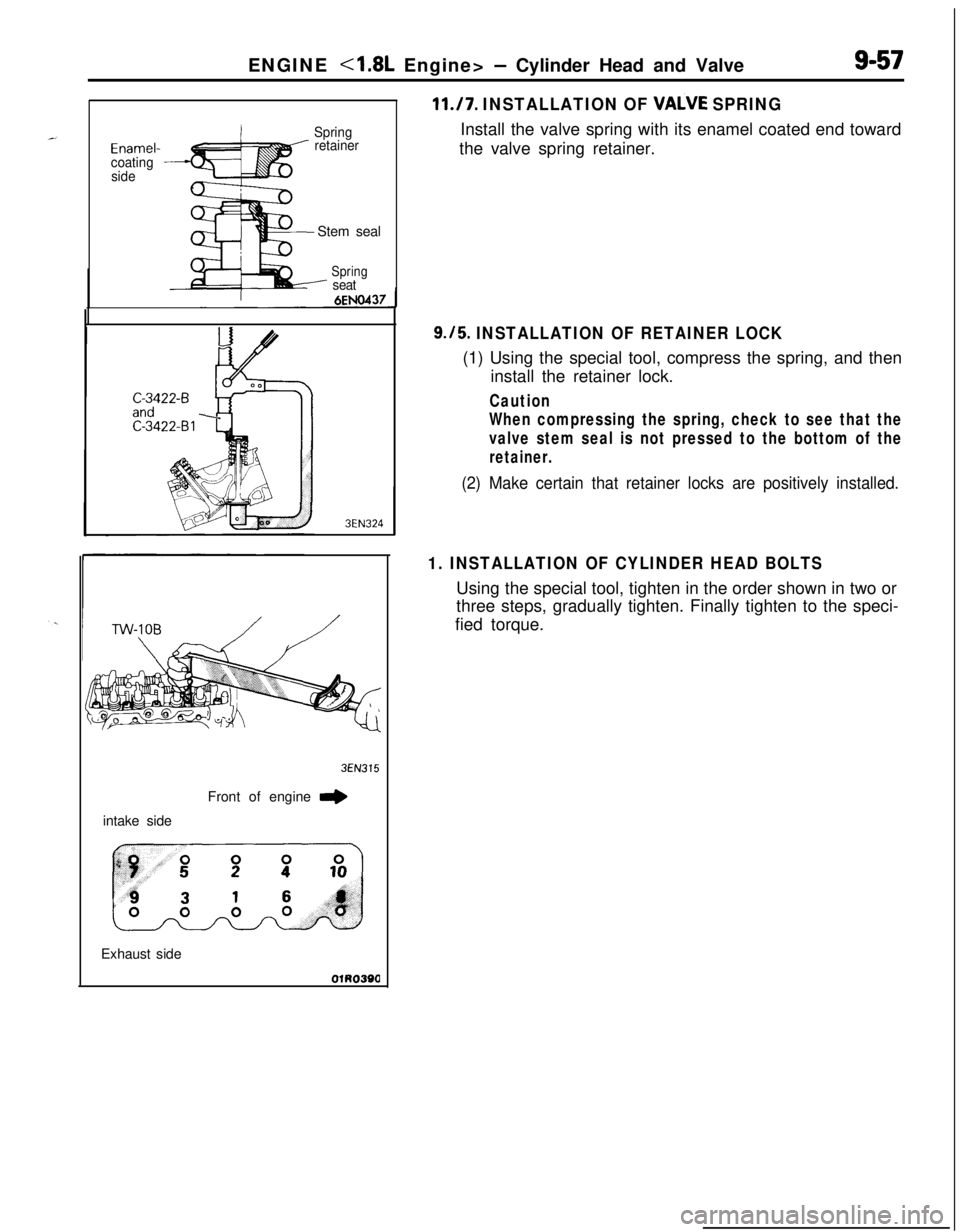
11./7. INSTALLATION OF VALVE SPRINGInstall the valve spring with its enamel coated end toward
the valve spring retainer.
9.15. INSTALLATION OF RETAINER LOCK(1) Using the special tool, compress the spring, and then
install the retainer lock.
Caution
When compressing the spring, check to see that the
valve stem seal is not pressed to the bottom of the
retainer.
(2) Make certain that retainer locks are positively installed.
1. INSTALLATION OF CYLINDER HEAD BOLTSUsing the special tool, tighten in the order shown in two or
three steps, gradually tighten. Finally tighten to the speci-
fied torque.