ESP MITSUBISHI ECLIPSE 1991 Workshop Manual
[x] Cancel search | Manufacturer: MITSUBISHI, Model Year: 1991, Model line: ECLIPSE, Model: MITSUBISHI ECLIPSE 1991Pages: 1216, PDF Size: 67.42 MB
Page 812 of 1216
MANUAL TRANSAXLE
vear210018
Springprotrusion
Key
201001::
TFM0023
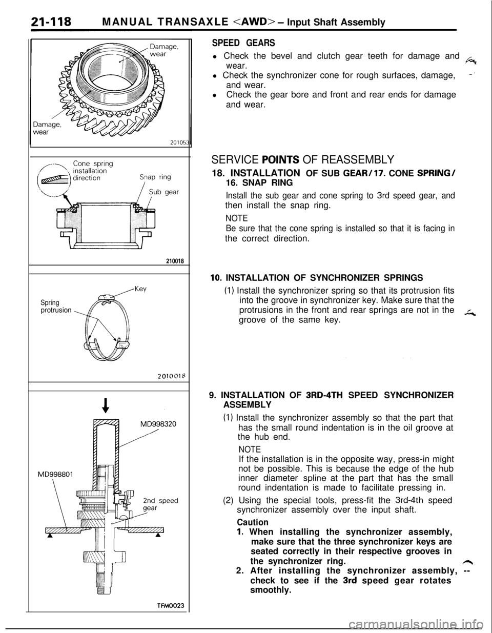
SPEED GEARSl Check the bevel and clutch gear teeth for damage and
.6
wear.l Check the synchronizer cone for rough surfaces, damage,
-‘and wear.
lCheck the gear bore and front and rear ends for damage
and wear.
SERVICE POlNTS OF REASSEMBLY18. INSTALLATION OF SUB
GEAR/17. CONE SPRING/16. SNAP RING
Install the sub gear and cone spring to 3rd speed gear, andthen install the snap ring.
NOTE
Be sure that the cone spring is installed so that it is facing inthe correct direction.
10. INSTALLATION OF SYNCHRONIZER SPRINGS
(1) Install the synchronizer spring so that its protrusion fits
into the groove in synchronizer key. Make sure that the
protrusions in the front and rear springs are not in the
in,groove of the same key.
9. INSTALLATION OF
3RD-4TH SPEED SYNCHRONIZER
ASSEMBLY
(1) Install the synchronizer assembly so that the part that
has the small round indentation is in the oil groove at
the hub end.
NOTEIf the installation is in the opposite way, press-in might
not be possible. This is because the edge of the hub
inner diameter
spline at the part that has the small
round indentation is made to facilitate pressing in.
(2) Using the special tools, press-fit the
3rd-4th speed
synchronizer assembly over the input shaft.
Caution
1. When installing the synchronizer assembly,
make sure that the three synchronizer keys are
seated correctly in their respective grooves in
the synchronizer ring.
h2. After installing the synchronizer assembly, --
check to see if the
3rd speed gear rotates
smoothly.
Page 831 of 1216
AUTOMATIC TRANSAXLE - General Information21437
AUTOMATIC TRANSAXLE
_,sGENERAL INFORMATION
NZlBABTaCautionary points during disassembly and
assembly of the transaxle
Because the automatic transaxle is composed ofcomponent parts of an especially high degree of
precision, these parts should be very carefully
handled during disassembly and assembly so asnot to scar or scratch them.
A rubber mat should be placed on the work-
bench, and it should always be kept clean.
During disassembly, cloth gloves or shop towelsshould not be used.
If such items must be used, use articles made ofnylon, or use paper towels.
All
disassemblyed parts must be thoroughly
cleaned.Metal parts may be cleaned with ordinary
detergents, but must be thoroughly air dried.
Clean the clutch disc, resin thrust plate and
rubber parts by using ATF (automatic transmis-
sion fluid), being very careful that dust, dirt, etc.
do not adhere.
Do not reuse gaskets, oil seals and rubber parts.Replace them with new ones at every reassem-
bly. O-ring of oil level gauge need not be
replaced.Do not use grease other than petrolatum jelly.
Apply ATF to friction element, rotating parts, andsliding parts before installation.
New clutch disc should be immersed in ATF for
more than two hours before installation.
Do not apply sealer or adhesive to gaskets.
When bushing must be replaced, replace
assembly which includes it.
If the transaxle main unit is damaged, also
disassembly and clean the cooler system.
In order to prevent a sudden start as a result of
accidental misoperation of the select lever, this
model is provided with the automatic-transaxle
safety-lock system.
Page 890 of 1216
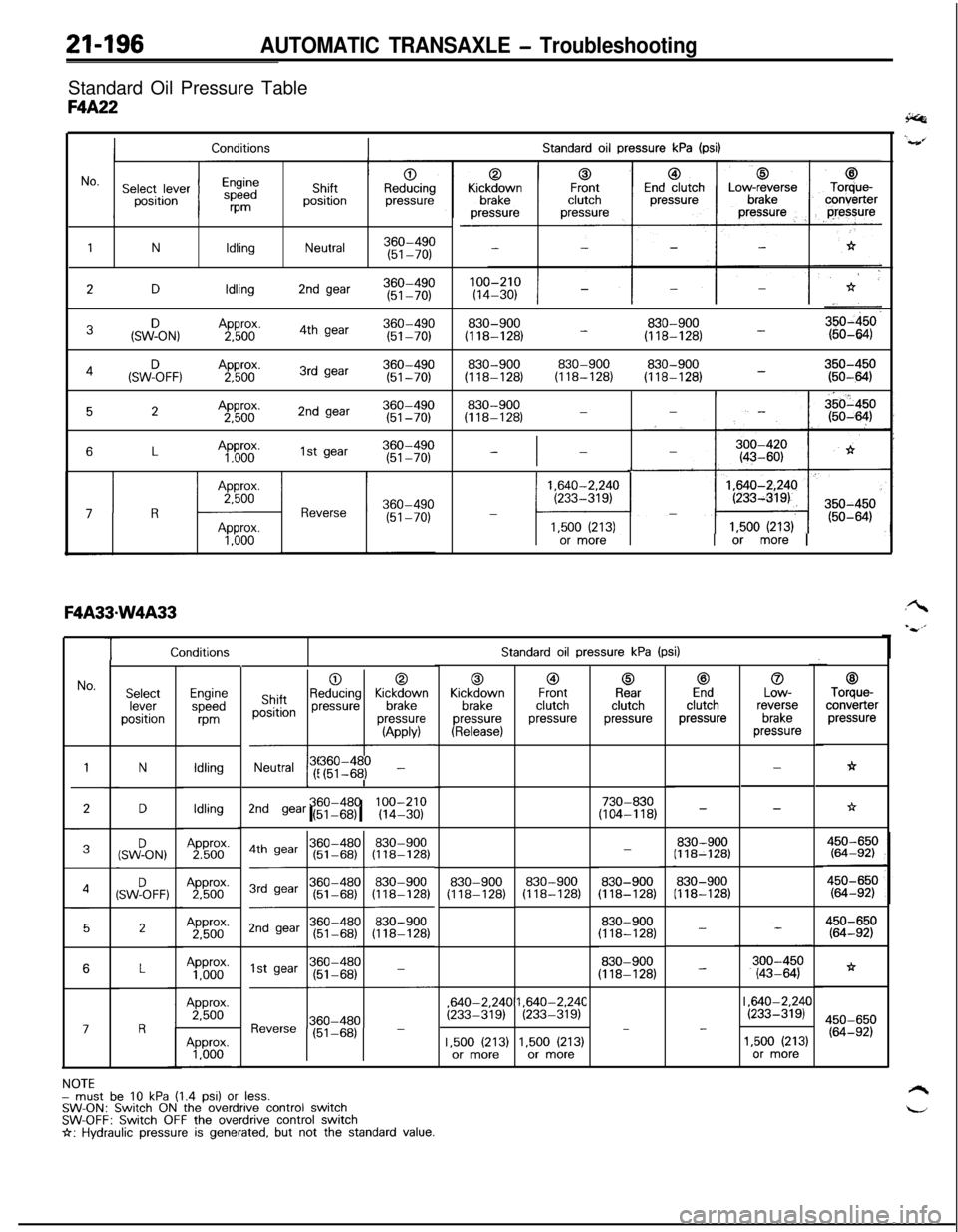
21-196AUTOMATIC TRANSAXLE - TroubleshootingStandard Oil Pressure Table
F4A22
Standard oil pressure kPa (psi)Conditions
1NIdlingNeutral360-490(51-70)
2DIdling2nd gear360-490(51-70)
3&ON,Approx.360-4902,5004th gear(51-70)830-900830-900(118-128) -(118-128) -
830-900830-900830-900350-450(118-128)(118-128)(118-128) -(50-6434(SWF)oFF, ,A2pp5boox.3rd gear360-490(51-70)
52Approx.2nd gear360-4902,500(51-70)830-900(118-128)-
6LAp”60”.1st gear360-490(51-70)-I-
1,640-2.240(233-319)-
l-41,500 (213)or more1 or more I
TStandard oil pressure kPa (psi)
0Kickdown
brakepressure
(Release)
@IFrontclutchpressure
0Rearclutchpressure
c3Endclutchpressure
0Low-reverse
brakepressure
00ShiftpositionReducing KickM;vnpressurepressure
-l---l
(APPM
Neutral !r$I$$ -
c3Torque-converter
pressure
h
No.SelectleverpositionEnginespeed
m
Idling
IdlingApprox.2,500Approx.
1,000Approx.2,500
N-
-
LI
*D730-830(104-118)2nd gear (51-68)I I360-480 100-210(14-30)-
830-900(118-128)(SWFON,-
830-900(118-128)830-900(118-128)4SW%FF:830-900(118-128)830-900(118-128)
2450-650(64-92)
*
450-650(64-92)
830-900(118-128)
830-900(118-128)
-
-6,640-2.24C
(233-319),640-2.24C(233-319)I ,640-2.24C(233-319)III
17-
1.500 (213)or more1,500 (213)or more1,500 (213)or more
NOTEmust be 10 kPa (1.4 psi) or less.SW-ON: Switch ON the overdrive control switchSW-OFF: Switch OFF the overdrive control switchI+: Hydraulic pressure is generated, but not the standard value.
Page 905 of 1216
AUTOMATIC TRANSAXLE - Service Adjustment Procedures21-21109A0146
OQMOO45
control lever
control lever
5 mm
Section A-A
(2 in.)Manual
controllever
Switch body
SHIFT LOCK MECHANISM CHECKN21FVAA
1.
2.
3.
4.Check to be sure that, under the following conditions, the
select lever cannot be moved from the
“P” position to any
other position.
Ignition key position: “ACC”
Brake pedal: Not depressedButton: Pressed
Check to be sure that, under the following conditions, the
select lever can be moved smoothly from the “P” position
to other position.
Ignition key position: “ACC”
Brake pedal: Depressed
Button: Pressed
Check to be sure that, under the following conditions, the
select lever can be moved smoothly from the “R” position
to the “P” position.
Ignition key position: “ACC”
Brake pedal: Released
Button: Pressed
If a malfunction is discovered when following the above
checking procedures, either adjust or check the shift lock
cable mechanism. (Refer to
P.21-220.)
INHIBITOR SWITCH ADJUSTMENTNZlFKAJ
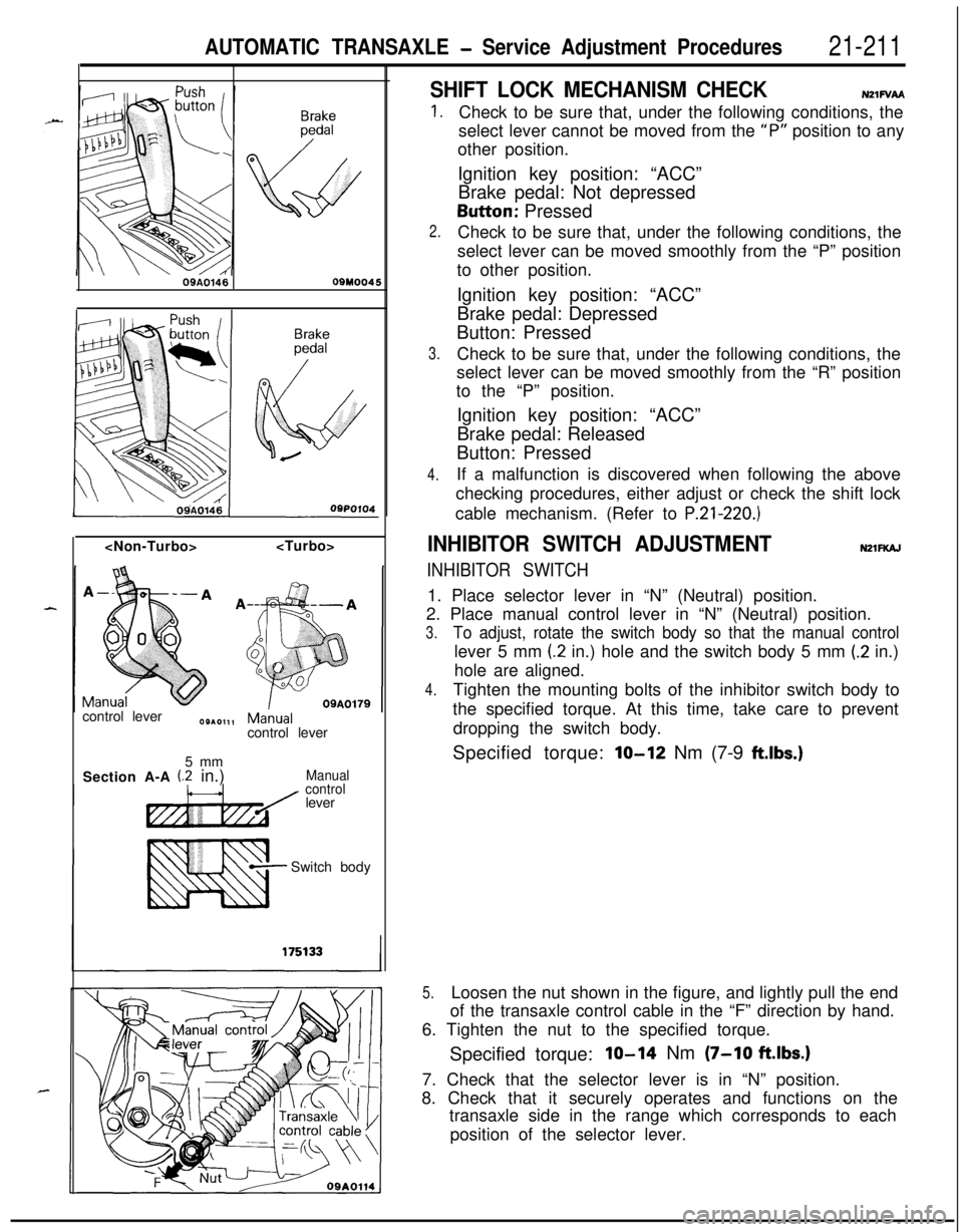
INHIBITOR SWITCH1. Place selector lever in “N” (Neutral) position.
2. Place manual control lever in “N” (Neutral) position.
3.To adjust, rotate the switch body so that the manual controllever 5 mm
(2 in.) hole and the switch body 5 mm (.2 in.)
hole are aligned.
4.Tighten the mounting bolts of the inhibitor switch body to
the specified torque. At this time, take care to prevent
dropping the switch body.
Specified torque:
lo-12 Nm (7-9 ftlbs.)
5.Loosen the nut shown in the figure, and lightly pull the end
of the transaxle control cable in the “F” direction by hand.
6. Tighten the nut to the specified torque.
Specified torque:
IO-14 Nm (7-10 ftlbs.)7. Check that the selector lever is in “N” position.
8. Check that it securely operates and functions on the
transaxle side in the range which corresponds to each
position of the selector lever.
Page 1039 of 1216
22-l-.
WHEELS
AND TIRES
CONTENTSNZZAA-
SERVICE ADJUSTMENT PROCEDURES.......4TROUBLESHOOTING......................................3
Tire
InflationPressureCheck......................4Bald Spots
TireWearCheck..........................................4Cracked Treads
Wheel
RunoutCheck...................................4Feathered Edge
SPECIFICATIONSRapid Wear at Center.............................................2
General
Specifications..................................2Rapid Wear at Shoulders
ServiceSpecificationsScalloped Wear...................................2Wear on One Side
7TorqueSpecifications...................................2
WHEEL AND TIRE..........................................5
Page 1043 of 1216
WHEELS AND TIRES - Wheel and Tire22-5
WHEEL AND TIRE
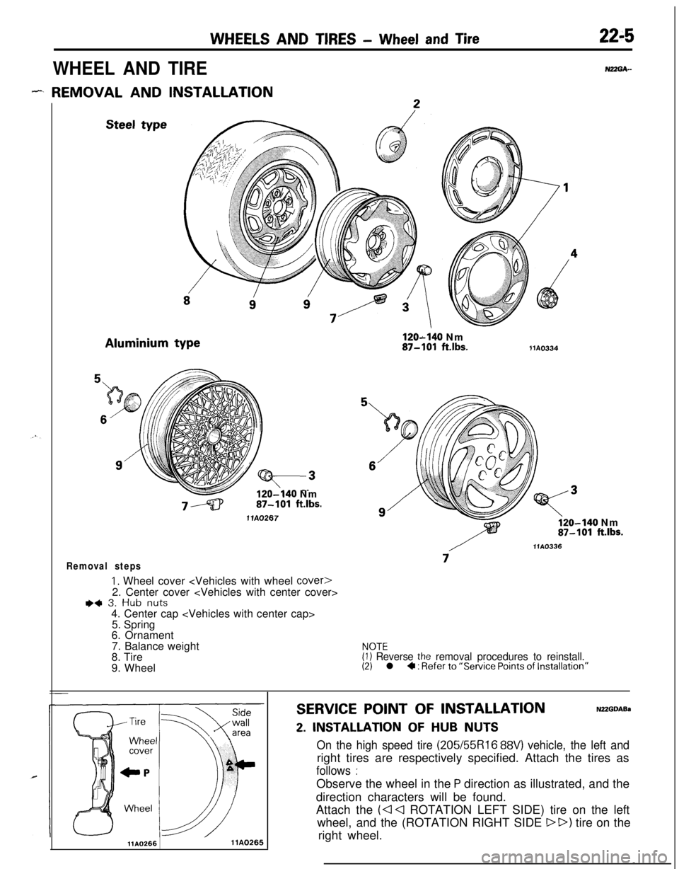
- REMOVAL AND INSTALLATIONSteel typeAluminium type
120-140 Nm87-101 ft.lbs.
1 lA0267
Removal steps
1. Wheel cover
I)+ 3. Hub nuts4. Center cap
5. Spring
6. Ornament
7. Balance weight
8. Tire
9. WheelNUGA-
120-140 Nm87-101 ftlbs.liA0334
o-140 Nm87-101 ft.lbs.
/llA0336
7
NOTE(1) Reverse the removal procedures to reinstall.(2) l 4 : Refer to “Service Points of Installation”
llAO2661 lAO265
SERVICE POINT OF INSTALLATIONNUGDABa
2. INSTALLATION OF HUB NUTS
On the high speed tire (205/55R16 88V) vehicle, the left andright tires are respectively specified. Attach the tires as
follows :Observe the wheel in the
P direction as illustrated, and the
direction characters will be found.
Attach the
(a Cl ROTATION LEFT SIDE) tire on the left
wheel, and the (ROTATION RIGHT SIDE
DD) tire on the
right wheel.
Page 1145 of 1216
24-l
HEATERS ANDAIR CONDITIONING
CONTENTSN24M--AIR CONDITIONER SWITCH
..........................30BLOWER ASSEMBLY
.....................................33
COMPRESSOR.................................................37CONDENSER AND CONDENSER FAN
MOTOR............................................................45ENGINE COOLANT TEMPERATURE
-‘-.,SWITCH............................................................51
EVAPORATOR.................................................
34
HEATERCONTROLASSEMBLY....................
26HEATER UNIT
.................................................31
REFRIGERANTLINE........................................47
RESISTOR........................................................29SAFETY PRECAUTIONS
.................................10SERVICE ADJUSTMENT PROCEDURES..
.....11Compressor Drive
Belt Adjustment
.............
23
CompressorNoise........................................24
Handling
TubingandFittings.......................22Idle-up
OperationCheck..............................25Manifold
GaugeSetInstallation..................11Performance Test
.........................................16Power Relay Check
......................................24Refrigerant Leak Repair Procedure
.............17
TestingSystemforLeaks...........................15Test Procedures
...........................................11
SPECIFICATIONS.............................................2
General Specifications..................................2
Lubricants......................................................3Sealant and Adhesives
.................................3Service Specifications
...................................2
TorqueSpecifications...................................2
TROUBLESHOOTING. . . ..a................................3
VENTILATORS(AIR INLET AND AIR OUTLET)
..,....s............. 50
VENTILATORS(INSTRUMENT PANEL)
..,...................*...........49
Page 1154 of 1216
24-10HEATERS AND AIR CONDITIONING - Safety Precautions
SAFETY PRECAUTIONSN24PAAD
The refrigerant used in all air conditioner is R-l 2. It istransparent and colorless in both the liquid and
vapor state. Since it has a boiling point of
-29.8”C(-85.6”F).
at atmospheric pressure, it will be a vapor
at all normal temperatures and pressures. The vaporis heavier than air, non-flammable, and nonexplo-
sive. It is nonpoisonous except when it is in direct
contact with open flame. It
ia noncorrosive except
when combined with water. The following precau-
tions must be observed when handling
R-12.Caution
Wear safety goggles when servicing the refriger-ation system.
R-12 evaporates so rapidly at normal atmospheric
pressures and temperatures that it tends to freeze
anything it contacts. For this reason, extreme care
must be taken to prevent any liquid refrigerant from
contacting the skin and especially the eyes. Always
wear safety goggles when servicing the refrigera-
tion part of the air conditioning system. Keep a
bottle of sterile mineral oil handy when working on
the refrigeration system. Should any liquid re-
frigerant get into the eyes, use a few drops of
mineral oil to wash them out.
R-12 is rapidly
absorbed by the oil. Next splash the eyes with
plenty of cold water. Call your doctor immediately
even though irritation has ceased after treatment.
Caution
Do not heat
R-12 above 40°C (104°F).In most instances, moderate heat is required to
bring the pressure of the refrigerant in its container
above the pressure of the system when charging or
adding refrigerant. A bucket or large pan of hot
water not over
40°C (104°F) is all the heat required
for this purpose. Do not heat the refrigerant contain-
er with a blow torch or any other means that would
raise temperature and pressure above this tempera-ture. Do not weld or steam clean on or near the
system components or refrigerant lines.
Caution
Keep
R-12 containers upright when charging the
system.When metering
R-12 into the refrigeration system,
keep the supply tank or cans in an upright position. Ifthe refrigerant container is on its side or upside
down, liquid refrigerant will enter the system and
damage the compressor.Caution
Always work in a well-ventilated room.
‘irrGood ventilation is vital in the working area. Always
discharge the refrigerant into the service bay ex-
haust system or outside the building. Large quanti-
ties of refrigerant vapor in a small, poorly ventilated
room can displace the air and cause suffocation.
Although
R-12 vapor is normally nonpoisonous,
contact with an open flame can cause the vapor to
become very poisonous. Do not discharge large
quantities of refrigerant in an area having an open
flame. A poisonous gas is produced when using theflame-type leak detector. Avoid inhaling the fumes
from the leak detector.
Caution
Do not allow liquid refrigerant to touch bright
metal.
Refrigerant will tarnish bright metal and chrome
surfaces, and in combination with moisture can
severely corrode all metal surfaces.
R-12 Refrigerant Bundling
Refrigerant Recycling
R-12 refrigerant is a chloro-floro-carbon (CFC) that
can contribute to the depletion of the ozone layer in
the upper atmosphere.A
Ozone filters out harmful radiation from the sun.
- -/.To assist in protecting the ozone layer, Mitsubishi
Motors Corporation
recomends that a R-12 re-
frigerant recycling device that meets SAE standard
J1991 be used.
Contact an automotive service equipment supplier
for refrigerant recycling equipment that is available
in your area.
Refer to the operating instructions provided with therecycling equipment for proper operation.
Page 1161 of 1216
HEATERS AND AIR CONDITIONING - Service Adjustment Procedures 24-Q
ilectric leakletector tester
2OUO333
40°C(I 04°F)20A0463
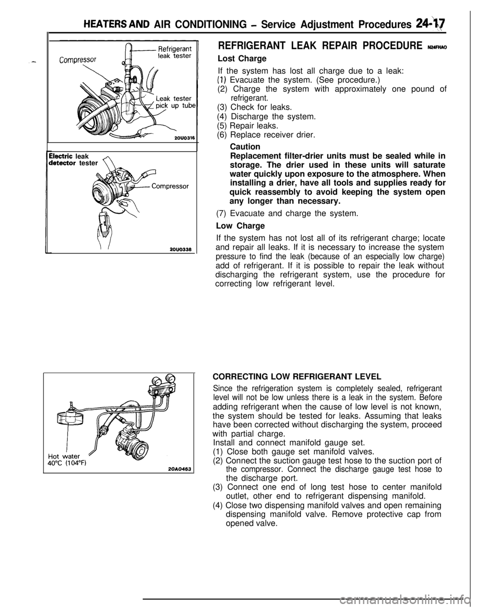
REFRIGERANT LEAK REPAIR PROCEDURE N24FtiAOLost Charge
If the system has lost all charge due to a leak:
(1) Evacuate the system. (See procedure.)
(2) Charge the system with approximately one pound of
refrigerant.(3) Check for leaks.
(4) Discharge the system.
(5) Repair leaks.
(6) Replace receiver drier.
Caution
Replacement filter-drier units must be sealed while in
storage. The drier used in these units will saturate
water quickly upon exposure to the atmosphere. When
installing a drier, have all tools and supplies ready for
quick reassembly to avoid keeping the system open
any longer than necessary.
(7) Evacuate and charge the system.
Low Charge
If the system has not lost all of its refrigerant charge; locate
and repair all leaks. If it is necessary to increase the system
pressure to find the leak (because of an especially low charge)add of refrigerant. If it is possible to repair the leak without
discharging the refrigerant system, use the procedure for
correcting low refrigerant level.
CORRECTING LOW REFRIGERANT LEVEL
Since the refrigeration system is completely sealed, refrigerant
level will not be low unless there is a leak in the system. Beforeadding refrigerant when the cause of low level is not known,
the system should be tested for leaks. Assuming that leaks
have been corrected without discharging the system, proceed
with partial charge.
Install and connect manifold gauge set.
(1) Close both gauge set manifold valves.
(2) Connect the suction gauge test hose to the suction port of
the compressor. Connect the discharge gauge test hose tothe discharge port.
(3) Connect one end of long test hose to center manifold
outlet, other end to refrigerant dispensing manifold.
(4) Close two dispensing manifold valves and open remaining
dispensing manifold valve. Remove protective cap from
opened valve.
Page 1197 of 1216
.^
EMISSION CONTROL
SYSTEMS
CONTENTSN25AA-
CATALYTICCONVERTER...............................20CRANKCASE EMISSION CONTROL
SYSTEM...........................................................7Components Location
...................................7Crankcase Ventilation System
Inspection......................................................8Positive Crankcase Ventilation Valve
...........8EVAPORATIVE EMISSION CONTROL
SYSTEM...........................................................9
AirConditionerSwitch.................................14Air Flow Sensor, Engine Coolant
Temperature Sensor and Intake Air
Temperature Sensor
.....................................14
Canister.........................................................14Components Location
...................................9
FuelFillerCapInspection............................14Overfill Limiter (Two-way Valve)
..................14
PurgeControlSolenoidValve......................13Purge Control
SystemInspection................11
PurgeControlValve
SYSTEM...........................................................15Air-fuel Ratio Control (MPI) System
............20Components Location
...................................15EGR Control Solenoid Valve
.................................................19
EGR
SystemInspection...............................17EGR Temperature Sensor
......19
EGR Valve.....................................................18
Therm0 Valve
SPECIFICATIONS.............................................2General Specifications
..................................2
Sealant..........................................................2Service Specifications
...................................2
TorqueSpecifications...................................2
TROUBLESHOOTING......................................3
VACUUMHOSES...........................................4
VacuumHosesRouting...............................4