Mpi MITSUBISHI ECLIPSE 1991 Service Manual
[x] Cancel search | Manufacturer: MITSUBISHI, Model Year: 1991, Model line: ECLIPSE, Model: MITSUBISHI ECLIPSE 1991Pages: 1216, PDF Size: 67.42 MB
Page 2 of 1216
2INTRODUCTION AND MASTER TROUBLESHOOTING - How to Use This Manual
HOW TO USE THIS MANUALNOaM
CONTENTSThe preceding page contains GROUP INDEX which
lists the group title and group number.
PAGE NUMBERS
All page numbers consist of two sets of digits
separated by a dash. The digits preceding the dash
identify the
number of the group. The digits follow-
ing the dash represent the consecutive page num-
ber within the group. The page numbers can be
found on the top left or right of each page.
TEXT
Unless otherwise specified, each service procedurecovers all models. Procedures covering specific
models are identified by the model codes, or similar
designation (engine type, transaxle type, etc.). A
description of these designations is covered in this
unit under “VEHICLE IDENTIFICATION”.
TROUBLESHOOTING
Troubleshootings are classified into master trouble-
shooting and group troubleshooting and located as
follows:
The master troubleshooting is prepared when the
trouble symptom relates to two or more groups and
given in MASTER TROUBLESHOOTING.
The group troubleshooting guide is prepared for
causes of problems related to that individual group
only; a troubleshooting guide is prepared for each
appropriate group.LIMIT
-9Shows the standard for judging the quality of a part
-
or assembly on inspection and,means the maximumor minimum value within which the part or assembly
must be kept functionally or in strength.
It is a value
established outside the range of standard value.
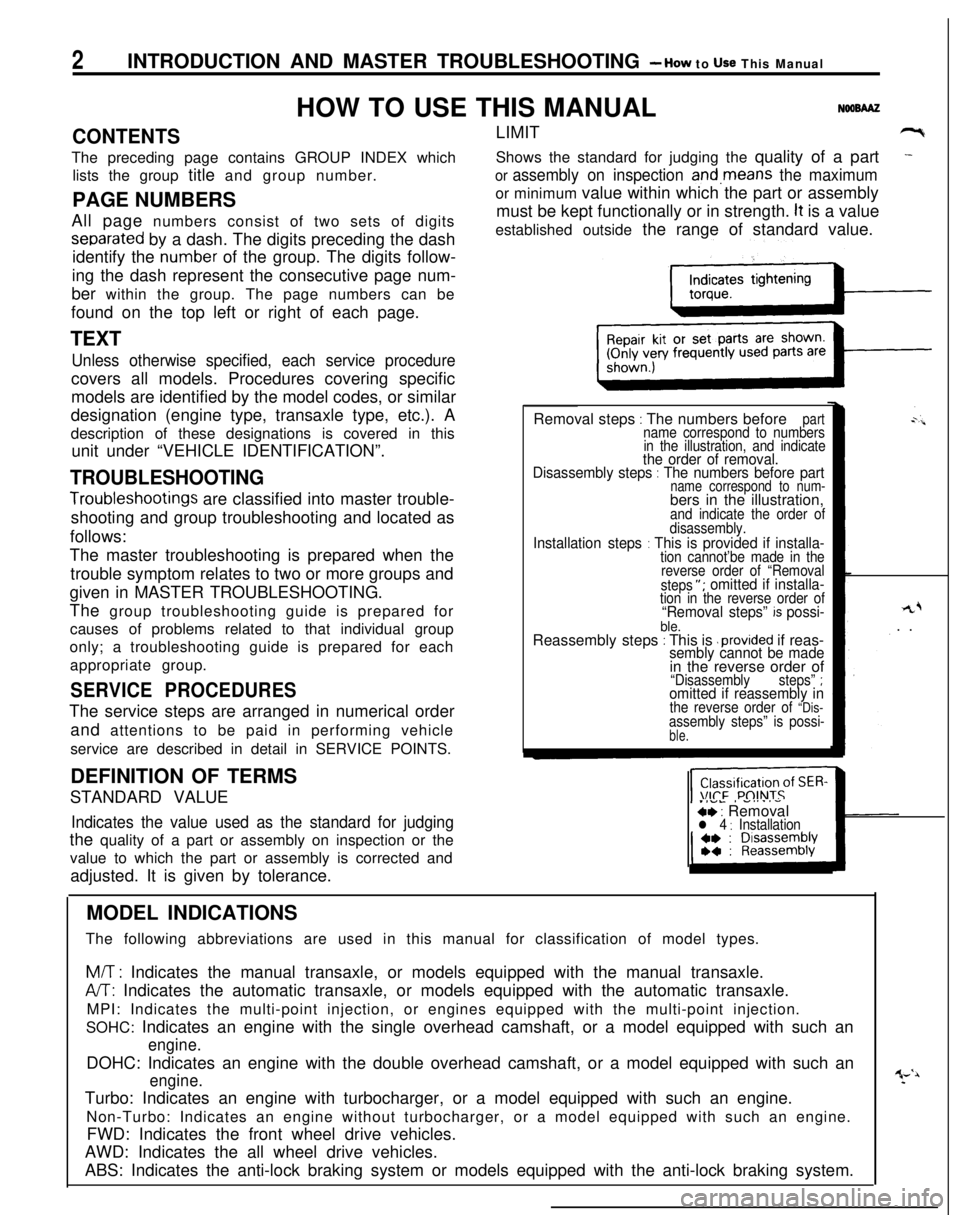
Removal steps
: The numbers beforepartname correspond to numbers
in the illustration, and indicate
the order of removal.
Disassembly steps : The numbers before partname correspond to num-bers in the illustration,
and indicate the order of
disassembly.
Installation steps : This is provided if installa-tion cannot’be made in the
reverse order of “Removal
steps
“; omitted if installa-tion in the reverse order of“Removal steps” k possi-ble.Reassembly steps : This is .provided if reas-sembly cannot be made
rL+. .
in the reverse order of
“Disassemblysteps” ;omitted if reassembly inthe reverse order of “Dis-assembly steps” is possi-ble.
SERVICE PROCEDURESThe service steps are arranged in numerical order
and attentions to be paid in performing vehicle
service are described in detail in SERVICE POINTS.
.IVL, -....-ce : Removall 4 : InstallationDEFINITION OF TERMS
STANDARD VALUEIndicates the value used as the standard for judgingthe quality of a part or assembly on inspection or the
value to which the part or assembly is corrected and
adjusted. It is given by tolerance.
MODEL INDICATIONS
The following abbreviations are used in this manual for classification of model types.
M/T : Indicates the manual transaxle, or models equipped with the manual transaxle.
A/T: Indicates the automatic transaxle, or models equipped with the automatic transaxle.
MPI: Indicates the multi-point injection, or engines equipped with the multi-point injection.
SOHC: Indicates an engine with the single overhead camshaft, or a model equipped with such an
engine.DOHC: Indicates an engine with the double overhead camshaft, or a model equipped with such an
engine.Turbo: Indicates an engine with turbocharger, or a model equipped with such an engine.
Non-Turbo: Indicates an engine without turbocharger, or a model equipped with such an engine.
FWD: Indicates the front wheel drive vehicles.
AWD: Indicates the all wheel drive vehicles.
ABS: Indicates the anti-lock braking system or models equipped with the anti-lock braking system.
Page 6 of 1216
6INTRODUCTION AND MASTER TROUBLESHOOTING - Vehicle Identificetion
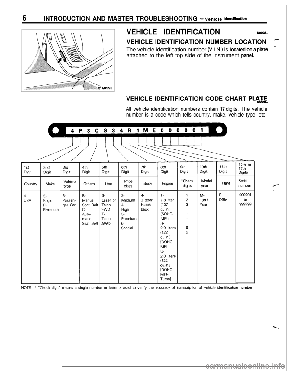
VEHICLE IDENTIFICATIONNmx-VEHICLE IDENTIFICATION NUMBER LOCATION
The vehicle identification number
(V.I.N.) is located oh a plate
attached to the left top side of the instrument panel.
VEHICLE IDENTIFICATION CODE CHART
PLA.4
All vehicle identification numbers contain 17 digits. The vehicle
number is a code which tells country, make, vehicle type, etc.
\5thDigit
r8thDigitr9thDigit
11thDigit12th to17thDigits
10thDigitModelyearM-
1991Year
7thDigitBody
4-
3 doorHatch-back
Engine
T-1.8 liter
(107cu.in.)[SOHC-MPI1R-2.0 liters(122
cu.in.)
[DOHC-
MPI]
u-2.0 liters
(122cuin.)[DOHC-MPI-Turbo]6thDigit
Price
class
3-Medium
4-
High5-Premium
6-Special
4thDigit
Others
B-Manual
Seat Beltc-
Auto-matic
Seat Belt
3rdDigitVehicleWe
3-Passen-ger
Car
2ndDigitMake
E-EagleP-Plymouth
1stDigitCountry
4-
USA
Serialnumber*CheckPlantLine
E-DSMS-Laser or
TalonFWDT-Talon
AWD
000001to
999999
I
NOTE* “Check digit” means a single number or letter x used to verify the accuracy of transcription of vehicle identification number.
Page 7 of 1216
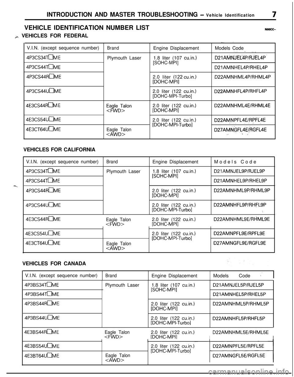
INTRODUCTION AND MASTER TROUBLESHOOTING - Vehicle IdentificationVEHICLE IDENTIFICATION NUMBER LIST
NOOCC--
p, VEHICLES FOR FEDERAL
,.. IV.I.N. (except sequence number)
BrandEngine DisplacementModels Code,,; * /./
4P3CS34aM EPlymouth Laser1.8 liter (107 cuin.)D21AMNJElXP/RJEL4P’
4P3CS44aME[SOHC-MPI]
D21AMNHEL4P/RHEL4P4P3CS44ROME2.0 liter
(122 cuin.)
[DOHC-MPI]D22AMNHML4P/RHML4P4P3CS44UuME2.0 liter (122
cu.in.)
[DOHC-MPI-Turbo]D22AMNHFL4P/RHFL4P
4E3CS44ROM EEap$DTrlon2.0 liter (122 cu.in.)
[DOHC-MPI]D22AMNHML4EIRHML4E4E3CS54UnME4E3CT64UOME
Eagle Talon
cu.in.)
[DOHC-MPI-Turbo]D22AMNPFL4EIRPFL4E
D27AMNGFL4E/kGFL4E.1L *,VEHICLES FOR CALIFORNIA
V.I.N. (except sequence number)
BrandEngine DisplacementModels Code
4P3CS34aMEPlymouth Laser1.8 liter (107 cu.in.)D21AMNJELSP/RJELSP
4P3CS44aME
[SOHC-MPI]D21AMNHELSP/RHELSP
4P3CS44RmME2.0 liter (122 cuin.)
[DOHC-MPI]
D22AMNHMLSP/RHMLSP4P3CS44UOME2.0 liter (122
cu.in.1[DOHC-MPI-Turbo]
D22AMNHFLSP/RHFLSP
‘.4E3CS44RuME
Eagle Talon2.0 liter (122 cu.in.1
D22AMNHMLSE/RHMLSE4E3CS54UOME4E3CT64UOME
Eagle Talon
cu.in.1[DOHC-MPI-Turbo]
D22AMNPFLSElRPFLSE
D27AMNGFLSE/RGFLSEVEHICLES FOR CANADA
V.I.N. (except sequence number)
BrandEngine DisplacementModels Code 1’1
4P3BS34aME
4P3BS44aMEPlymouth Laser1.8 liter (107
cu.in.1[SOHC-MPI]D21AMNJEL5P/RJEL5PD21AMNHiL5P/RHEL5P4P3BS44ROME
2.0 liter (122
cuin.)
[DOHC-MPI]D22AMNHML5P/RHML5P4P3BS44UuME
2.0 liter (122
cu.in.)[DOHC-MPI-Turbo]D22AMNHFL5P/RHFL5P4E3BS44ROME
Eagle Talon2.0 liter (122 cu.in.)D22AMNHML5EiRHML5E
Eagle Talon
cu.in.1
[DOHC-MPI-Turbo]
Page 8 of 1216
8INTRODUCTION AND MASTER TROUBLESHOOTING - Vehicle Identification
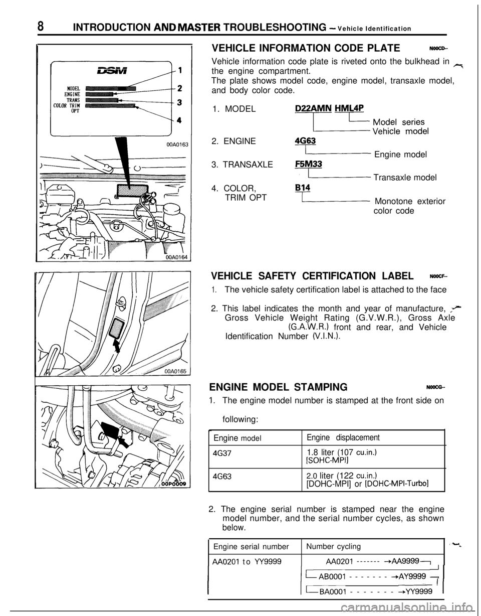
VEHICLE INFORMATION CODE PLATE
NOOCD-Vehicle information code plate is riveted onto the bulkhead in
rithe engine compartment.
The plate shows model code, engine model, transaxle model,
and body color code.
1. MODEL
2. ENGINE
3. TRANSAXLE
4. COLOR,
TRIM OPTD22AMN
HML4P
2 y$y:/e ‘f$$l
4G63
I Engine modelF5M33
y Transaxle model
B14
I Monotone exterior
color code
VEHICLE SAFETY CERTIFICATION LABELNOOCF-
1.The vehicle safety certification label is attached to the face
2. This label indicates the month and year of manufacture,
;eGross Vehicle Weight Rating (G.V.W.R.), Gross Axle
(G.A.W.R.) front and rear, and Vehicle
Identification Number
(V.I.N.).ENGINE MODEL STAMPING
NOOCG-
1.The engine model number is stamped at the front side on
following:
Engine model4637Engine displacement
1.8 liter (107 cu.in.)
[SOHC-MPI]
4G632.0 liter (122 cuin.)
[DOHC-MPI] or
[DOHC-MPI-Turbo]2. The engine serial number is stamped near the engine
model number, and the serial number cycles, as shown
below.Engine serial numberNumber cycling
AA0201 to w9999AA0201 ------- -*AA99997
I1 LAB0001 ------- +AY9999 : 1
I1 t-BAOOOI ------- +YY9999 ’ 1
‘-w
Page 14 of 1216
I4INTRODUCTION AND MASTER TROUBLESHOOTING - Precautions before Service
mm (In.1smo59
PARTSWhen replacing parts, use MOPAR genuine parts.
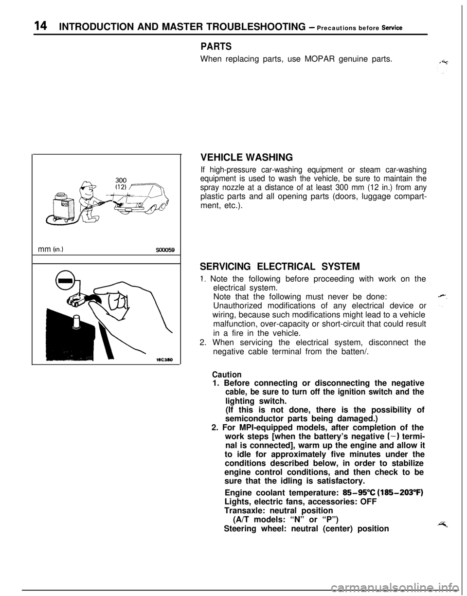
VEHICLE WASHING
If high-pressure car-washing equipment or steam car-washing
equipment is used to wash the vehicle, be sure to maintain the
spray nozzle at a distance of at least 300 mm (12 in.) from anyplastic parts and all opening parts (doors, luggage compart-
ment, etc.).
SERVICING ELECTRICAL SYSTEM
1. Note the following before proceeding with work on the
electrical system.
Note that the following must never be done:
Unauthorized modifications of any electrical device or
wiring, because such modifications might lead to a vehicle
malfunction, over-capacity or short-circuit that could result
in a fire in the vehicle.
2. When servicing the electrical system, disconnect the
negative cable terminal from the batten/.
Caution1. Before connecting or disconnecting the negative
cable, be sure to turn off the ignition switch and thelighting switch.
(If this is not done, there is the possibility of
semiconductor parts being damaged.)
2. For MPI-equipped models, after completion of the
work steps [when the battery’s negative
(-) termi-
nal is connected], warm up the engine and allow it
to idle for approximately five minutes under the
conditions described below, in order to stabilize
engine control conditions, and then check to be
sure that the idling is satisfactory.
Engine coolant temperature:
85-95°C (185-203°F)
Lights, electric fans, accessories: OFF
Transaxle: neutral position
(A/T models: “N” or “P”)
Steering wheel: neutral (center) position
Page 19 of 1216
c
--INTRODUCTION AND MASTER
TROUBLESHOOTtNG - Towing and Hoi&gT9
I-
Sling type
Wheel lift type
Flat bed type
iling type
Vheel lift type
lat bed type
TOWING AND HOISTINGNOOGA-
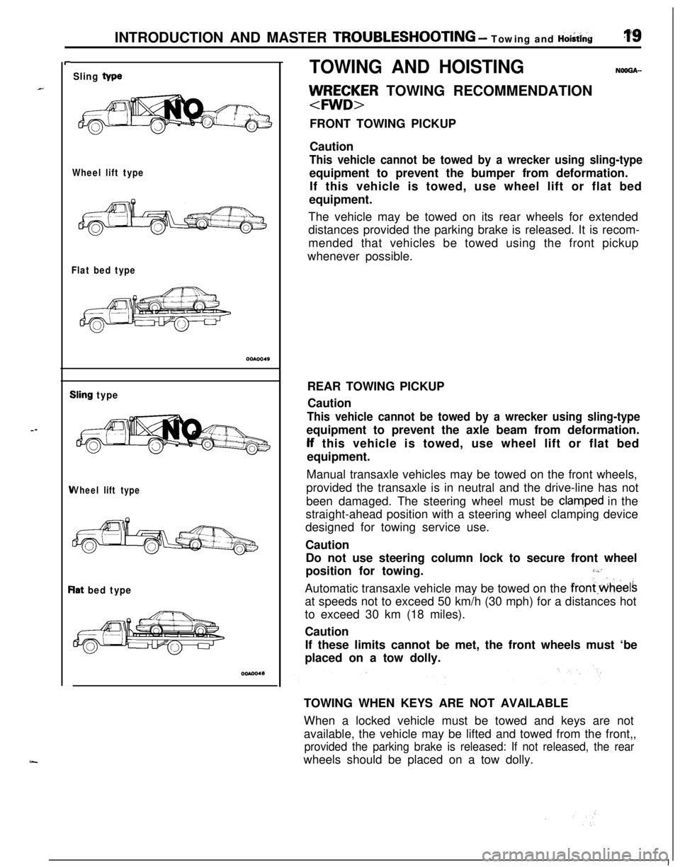
llJ/RE;~R TOWING RECOMMENDATION
FRONT TOWING PICKUP
Caution
This vehicle cannot be towed by a wrecker using sling-typeequipment to prevent the bumper from deformation.
If this vehicle is towed, use wheel lift or flat bed
equipment.
The vehicle may be towed on its rear wheels for extended
distances provided the parking brake is released. It is recom-
mended that vehicles be towed using the front pickup
whenever possible.
REAR TOWING PICKUP
Caution
This vehicle cannot be towed by a wrecker using sling-typeequipment to prevent the axle beam from deformation.lf this vehicle is towed, use wheel lift or flat bed
equipment.
Manual transaxle vehicles may be towed on the front wheels,
provided the transaxle is in neutral and the drive-line has not
been damaged. The steering wheel must be
clam,ped in the
straight-ahead position with a steering wheel clamping device
designed for towing service use.
Caution
Do not use steering column lock to secure front wheel
position for towing.
3,“’Automatic transaxle vehicle may be towed on the
frontwheelsat speeds not to exceed 50 km/h (30 mph) for a distances hot
to exceed 30 km (18 miles).
Caution
If these limits cannot be met, the front wheels must ‘be
placed on a tow dolly.
TOWING WHEN KEYS ARE NOT AVAILABLE
When a locked vehicle must be towed and keys are not
available, the vehicle may be lifted and towed from the front,,
provided the parking brake is released: If not released, the rearwheels should be placed on a tow dolly.
I
Page 36 of 1216
o-2LUBRICATION AND MAINTENANCE - General Information
GENERAL INFORMATIONNGQPA--Maintenance and lubrication service recommenda-
tions have been compiled to provide maximum
protection for the vehicle owner’s investment
against all reasonable types of driving conditions.
Since these conditions vary with the individual
vehicle owner’s driving habits, the area in which the
vehicle is operated and the type of driving to which
the vehicle is subjected, it is necessary to prescribe
lubrication and maintenance service on a time
frequency as well as mileage interval basis.
Oils, lubricants and greases are classified and
graded according to standards recommended by theSociety of Automotive Engineers (SAE), the Amer-
ican Petroleum Institute (API) and the National
Lubricating Grease Institute
(NLGI).MAINTENANCE SCHEDULES
Information for service maintenance is provided
under “SCHEDULED MAINTENANCE TABLE”.
Three schedules are provided; one for “Required
Maintenance”, one for “General Maintenance” and
one for “Severe Usage Service”.
Item numbers in the “SCHEDULED MAINTE-
NANCE TABLE” correspond to the item numbers in
the “MAINTENANCE SERVICE” section.
SEVERE SERVICEVehicles operating under severe service conditions
will require more frequent service.
Component service information is included in
appropriate units for vehicles operating under one ormore of the following conditions:
1.Trailer towing or police, taxi, or commercial type
operation2. Operation of Vehicle
(1) Short-trip operation at freezing temperature
(engine not thoroughly warmed up)
(2) More than 50% operation in heavy city
traffic during hot weather above
32°C (90°F)(3) Extensive idling
(4) Driving in sandy areas
(5) Driving in salty areas
(6) Driving in dusty conditions
ENGINE OIL
The SAE grade number indicates the viscosity of
engine oils, for example, SAE 30, which is a single
grade oil. Engine oils are also identified by a dual
number, for example, SAE
lOW-30, which indicates
a multigrade oil.
The API classification system defines oil perform-
ance in terms of engine usage. Only engine oil
designed “For Service SG” or “For Service
SGKD”,when available, should be used. These oils contain
sufficient chemical additives to provide maximum
engine protection. Both the SAE grade and the API
designation can be found on the container.Caution
Test results submitted to EPA have shown thatlaboratory animals develop skin cancer after
prolonged contact with used engine oil. Accor-
dingly, the potential exists for humans
to de-
velop a number of skin disorders, including
cancer, from such exposure to used engine oil.
Care should be’ taken, therefore, when changingengine oil, to minimize the amount and length of
exposure time to used engine
pi! on your skin.
Protective clothing and gloves, that cannot be
penetrated by oil, should be worn. The skin
should be thoroughly washed with soap and
water, or use waterless hand cleaner, to removeany used engine oil. Do not use gasoline,
thinners, or solvents.
GEAR LUBRICANTSThe SAE grade number also indicates the viscosity
of Multi-Purpose Gear Lubricants.
The API classfication system defines gear lubricants
in terms of usage. Typically gear lubricants conform-ing to API
GL-4 or GL-5 with a viscosity of SAE
75W-85W are recommended for manual transaxle.
LUBRICANTS
- GREASES
Semi-solid lubricants, bear the NLGI designation andare further classified as grades 0, 1, 2, 3 etc.
Whenever “Chassis Lubricant” is specified, Multi-
Purpose Grease,
NLGI grade 2 should be used.
MOPAR Multi-Mileage Lubricant, P&t Number
2525035 or equivalent, meets these requirement
and is recommended.
FUEL USAGE STATEMENT
Use gasolines having a minimum anti-knock index
(Octane Value) of 87,
(R + M)/2. This designation is
comparable to a Research Octane Number of 91.
Unleaded gasolines only must be used in vehicles
equipped with catalyst emission control systems.
All vehicles, so equipped, have labels located on the
instrument panel and on the back of fuel filler lid that
state, “UNLEADED GASOLINE ONLY”. These vehi-
cles also have fuel filler tubes especially designed toaccept the smaller diameter unleaded gasoline
dispensing nozzles only.
MATERIALS ADDED
TO FUELIndiscriminate use of fuel system cleanng agents
should be avoided. Many of these materials in-
tended for gum and varnish removal may contain
highly active solvents or similar ingredients that can
be harmful to gasket and diaphragm materials usedin fuel system component parts.
Page 50 of 1216
2-2FRONT SUSPENSION - Specifications
SPECIFICATIONS
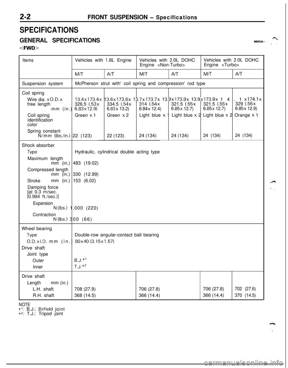
GENERAL SPECIFICATIONSNOZCA-
ItemsVehicles with 1.8L EngineVehicles with 2.0L DOHCVehicles with 2.0L DOHC
Engine
MM/TAITMITNTSuspension systemMcPherson strut with’ coil spring and compression’ rod type
Coil spring
Wire dia.
x0.D. x13.4x173.4x 13.6x173.6x 13.7x173.7x 13.9x173.9x 13.9x173.9x 14.1 x174.1xfree length326.5 (.53x334.5 (.54x314 (.54x321.5 (.55x321.5 (.55x329 (.55x
mm (in.) 6.83x12.9)6.83x
13.2)6.84x 12.4)6.85x 12.7)6.85x 12.7)6.85x 12.9)Coil springGreen
x 1Green x 2Light blue x 1 Light blue x 2 Light blue x 2 Orange x 1
identification
colorSpring constant
N/mm
(IbsAn.) 22 (123)22 (123)24 (134)24 (134)24 (134)24 (134)Shock absorber
TypeHydraulic, cylindrical double acting type
Maximum length
mm (in.) 483 (19.02)
Compressed length
mm (in.) 330 (12.99)
Strokemm (in.) 153 (6.02)
Damping force
[at 0.3
m/set.
(0.984 ft./sec.)l
Expansion
N (Ibs.) 1,000 (220)
ContractionN (Ibs.) 300 (66)
Wheel bearing
TypeDouble-row angular-contact ball bearing
0.D.xl.D. mm (in.) 80x40 (3.15x1.57)
Drive shaft
Joint type
OuterB.J.“l
InnerT.J.“’Drive shaft
Lengthmm (in.)
L.H. shaft708 (27.9)706 (27.8)
R.H. shaft368 (14.5)366 (14.4)
NOTE*1: B.J.: Birfield joint*2: T.J.: Tripod joint706 (27.8)
702 (27.6)366 (14.4)
370 (14.5)
Page 51 of 1216
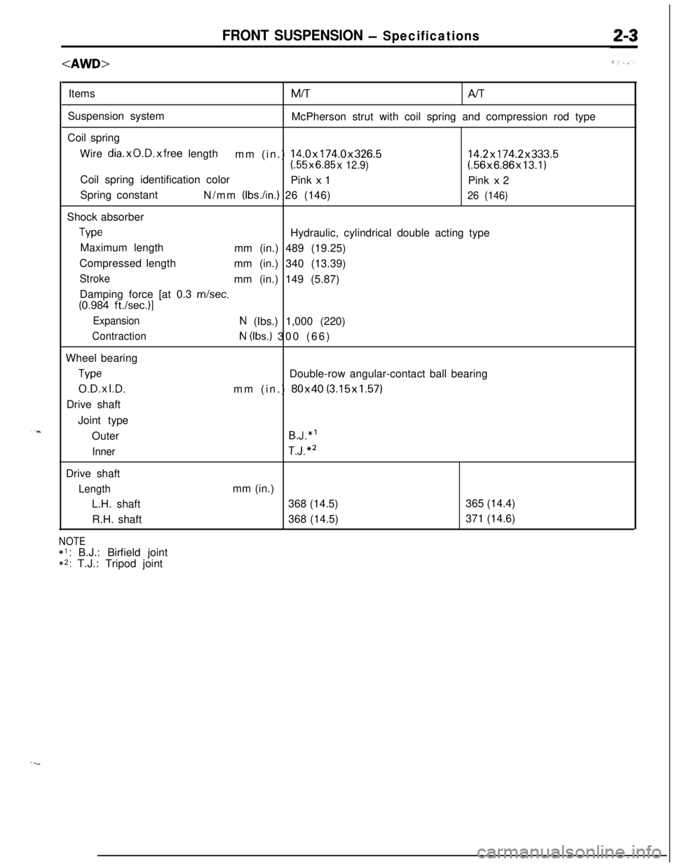
FRONT SUSPENSION - SpecificationsItemsMiT
Al-rSuspension system
McPherson strut with coil spring and compression rod type
Coil spring
Wire
dia.xO.D.xfree length
mm (in.) 14.0x174.0x326.514.2x174.2x333.5(.55x6.85x 12.9)(.56x6.86x13.1)
Coil spring identification color
Pink
x 1
Pink x 2
Spring constant
N/mm
(Ibs./in.) 26 (146)26 (146)Shock absorber
TypeHydraulic, cylindrical double acting type
Maximum length
mm (in.) 489 (19.25)
Compressed length
mm (in.) 340 (13.39)
Strokemm (in.) 149 (5.87)
Damping force [at 0.3 m/set.
(0.984 ft./set.)]
ExpansionN (Ibs.) 1,000 (220)
ContractionN (Ibs.) 300 (66)
Wheel bearing
TypeDouble-row angular-contact ball bearing
0.D.xl.D.mm (in.) 80x40 (3.15x1.57)
Drive shaft
Joint type
Outer
B.J.“’
InnerT.J.“’Drive shaft
Lengthmm (in.)
L.H. shaft368 (14.5)365 (14.4)
R.H. shaft368 (14.5)371 (14.6)
NOTE
*I: B.J.: Birfield joint**: T.J.: Tripod joint
Page 109 of 1216
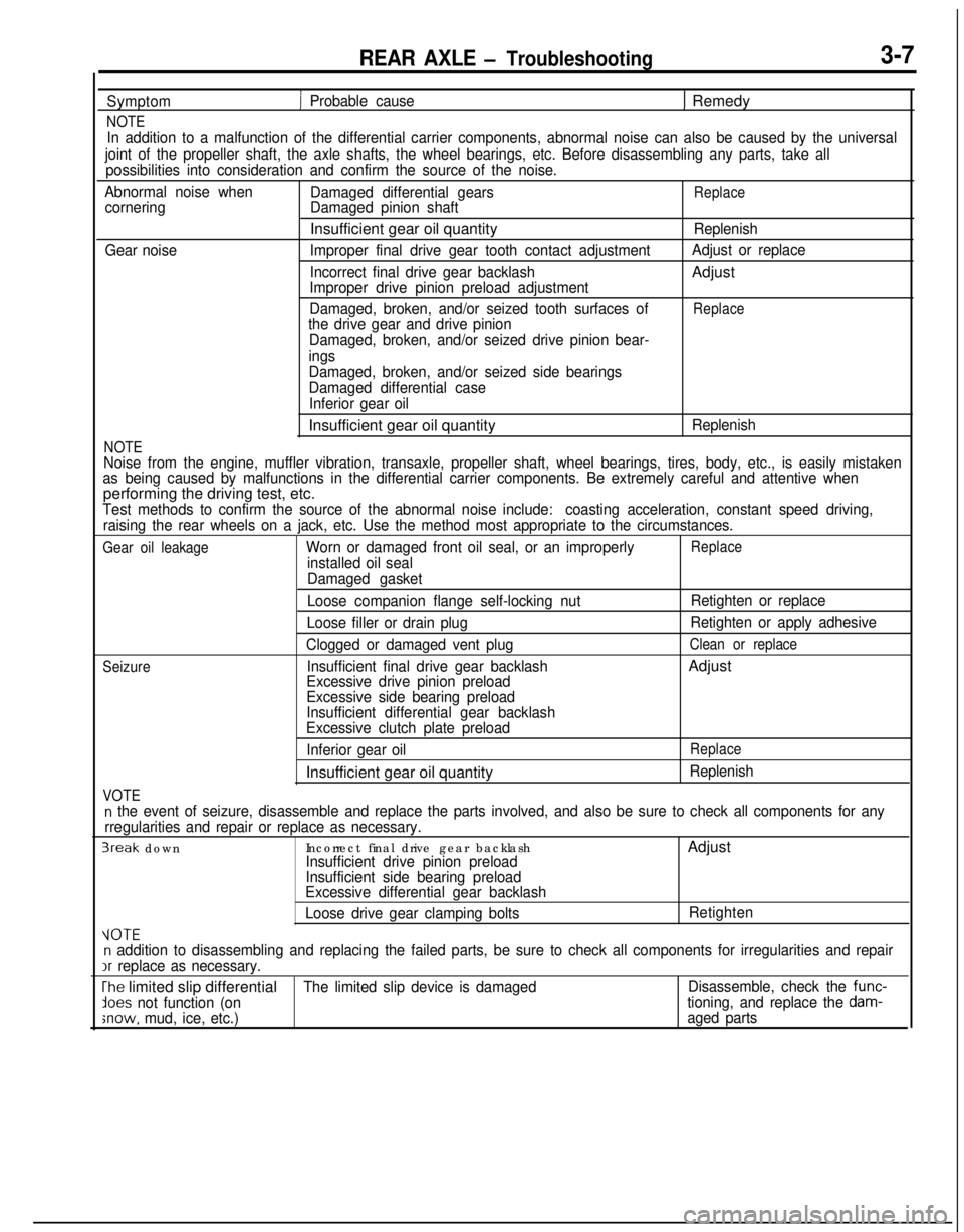
REAR AXLE - Troubleshooting3-7
Symptom
NOTE
1 Probable cause1 Remedy
In addition to a malfunction of the differential carrier components, abnormal noise can also be caused by the universal
joint of the propeller shaft, the axle shafts, the wheel bearings, etc. Before disassembling any parts, take all
possibilities into consideration and confirm the source of the noise.
Abnormal noise when
Damaged differential gears
ReplacecorneringDamaged pinion shaftInsufficient gear oil quantity
Replenish
Gear noiseImproper final drive gear tooth contact adjustmentAdjust or replace
Incorrect final drive gear backlashAdjust
Improper drive pinion preload adjustment
Damaged, broken, and/or seized tooth surfaces of
Replacethe drive gear and drive pinion
Damaged, broken, and/or seized drive pinion bear-
ings
NOTE
Damaged, broken, and/or seized side bearings
Damaged differential case
Inferior gear oilInsufficient gear oil quantity
Replenish
Noise from the engine, muffler vibration, transaxle, propeller shaft, wheel bearings, tires, body, etc., is easily mistaken
as being caused by malfunctions in the differential carrier components. Be extremely careful and attentive whenperforming the driving test, etc.
Test methods to confirm the source of the abnormal noise include:coasting acceleration, constant speed driving,
raising the rear wheels on a jack, etc. Use the method most appropriate to the circumstances.
Gear oil leakageWorn or damaged front oil seal, or an improperlyReplace
installed oil seal
Damaged gasket
Seizure
VOTE
Loose companion flange self-locking nut
Loose filler or drain plug
Clogged or damaged vent plug
Insufficient final drive gear backlash
Excessive drive pinion preload
Excessive side bearing preload
Insufficient differential gear backlash
Excessive clutch plate preload
Inferior gear oilInsufficient gear oil quantityRetighten or replace
Retighten or apply adhesive
Clean or replaceAdjust
Replace
Replenish
n the event of seizure, disassemble and replace the parts involved, and also be sure to check all components for any
rregularities and repair or replace as necessary.
3reak downIncorrect final drive gear backlashAdjustInsufficient drive pinion preload
Insufficient side bearing preload
Excessive differential gear backlash
Loose drive gear clamping boltsRetighten
VOTEn addition to disassembling and replacing the failed parts, be sure to check all components for irregularities and repairIr
replace as necessary.
The limited slip differentialThe limited slip device is damagedDisassemble, check the func-
lees not function (ontioning, and replace the dam-
;now, mud, ice, etc.)aged parts