reset MITSUBISHI ECLIPSE 1991 Service Manual
[x] Cancel search | Manufacturer: MITSUBISHI, Model Year: 1991, Model line: ECLIPSE, Model: MITSUBISHI ECLIPSE 1991Pages: 1216, PDF Size: 67.42 MB
Page 242 of 1216

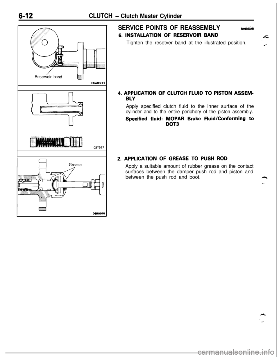
6-12CLUTCH - Clutch Master CylinderResew&r
bandk
oaA0058
08Y517
Grease
SERVICE POINTS OF REASSEMBLYNaaNciAN
6. INSTALLATION OF RESERVOIR BAND
Tighten the resetver band at the illustrated position.
4. APPLICATION OF CLUTCH FLUID TO PISTON ASSEM-
BLYApply specified clutch fluid to the inner surface of the
cylinder and to the entire periphery of the piston assembly.
Specified fluid: MOPAR Brake Fluid/Conforming to
DOT3
2. APPLICATION OF GREASE TO PUSH RODApply a suitable amount of rubber grease on the contact
surfaces between the damper push rod and piston and
between the push rod and boot.
Page 387 of 1216

ENGINE <2.0L DOHC Engine> - Timing Belts-103
--
Plug
6EN0281Center bolt
I
6EN028321. INSTALLATION OF AUTO TENSIONER
(1) If the auto tensioner rod is in its fully extended position,reset it as follows.
@ Keep the a t tu oensioner level and, in that position,
clamp it in the vise with soft jaws.
If the plug at the bottom of the auto tensioner
protrudes, surround it with a plain washer as
illustrated to prevent the plug from being in direct
contact with the vise.
@I Push in the rod little by little with the vise until the
set hole
@ in the rod is aligned with that @I in the
cylinder.
@ Insert a wire [1.4 mm (055 in.) in diameter] into the
set holes.
@I Unclamp the auto tensioner from the vise.
(2) Install the auto tensioner.
Caution
Leave the wire installed in the auto tensioner.
23. INSTALLATION OF TENSIONER PULLEY
(1) Install the tensioner pulley onto the tensioner arm.
(2) Locate the pinhole in the tensioner pulley shaft to the
left of the center bolt. Then, tighten the center bolt
finger-tight.Caution
Leave the wire installed in the auto tensioner.
Page 576 of 1216

14-122AUTO-CRUISE CONTROL SYSTEM - Troubleshooting
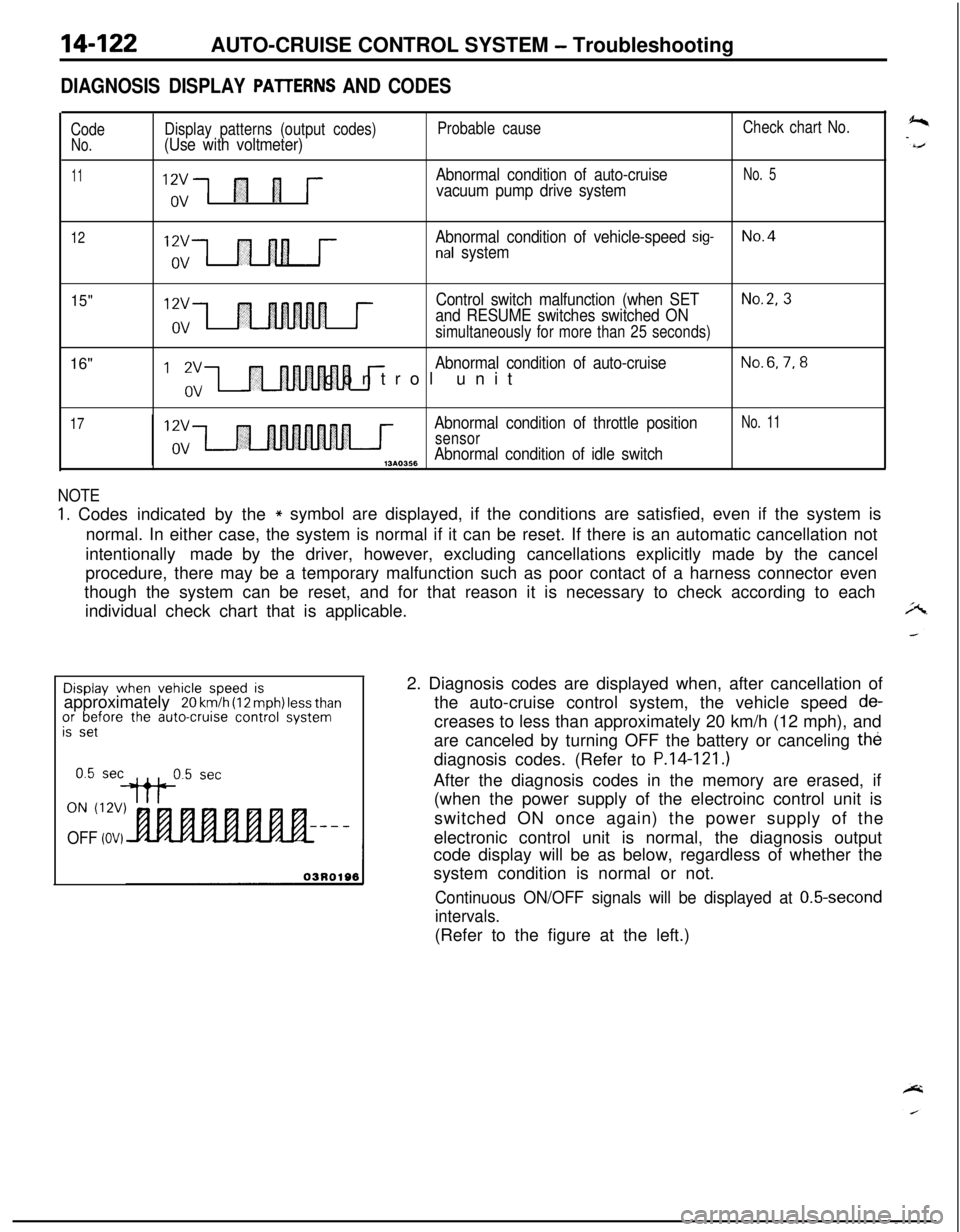
DIAGNOSIS DISPLAY PAlTERNS AND CODES
CodeNo.
11
Display patterns (output codes)(Use with voltmeter)
“,;1 fl 1 j--
Probable cause
Abnormal condition of auto-cruise
vacuum pump drive system
Check chart No.
No. 5
12Abnormal condition of vehicle-speed sig-No.4nal system
15"16"12vControl switch malfunction (when SETNo.2, 3
and RESUME switches switched ONovsimultaneously for more than 25 seconds)
I ‘,“,-I r
Abnormal condition of auto-cruiseNo.6,7,8control unit
17Abnormal condition of throttle positionNo. 11
sensorAbnormal condition of idle switch,3*0356
NOTE
1. Codes indicated by the* symbol are displayed, if the conditions are satisfied, even if the system is
normal. In either case, the system is normal if it can be reset. If there is an automatic cancellation not
intentionally made by the driver, however, excluding cancellations explicitly made by the cancel
procedure, there may be a temporary malfunction such as poor contact of a harness connector even
though the system can be reset, and for that reason it is necessary to check according to each
individual check chart that is applicable.Display
when vehicle speed isapproximately 20 km/h (12 mph) less thanor before the auto-cruise control systemis set
ON (12V)
OFF (OV)2. Diagnosis codes are displayed when, after cancellation of
the auto-cruise control system, the vehicle speed
de-creases to less than approximately 20 km/h (12 mph), and
are canceled by turning OFF the battery or canceling the
diagnosis codes. (Refer to
P.14-121.)After the diagnosis codes in the memory are erased, if
(when the power supply of the electroinc control unit is
switched ON once again) the power supply of the
electronic control unit is normal, the diagnosis output
code display will be as below, regardless of whether the
system condition is normal or not.
Continuous ON/OFF signals will be displayed at 0.5-second
intervals.(Refer to the figure at the left.)
Page 1046 of 1216

23-2
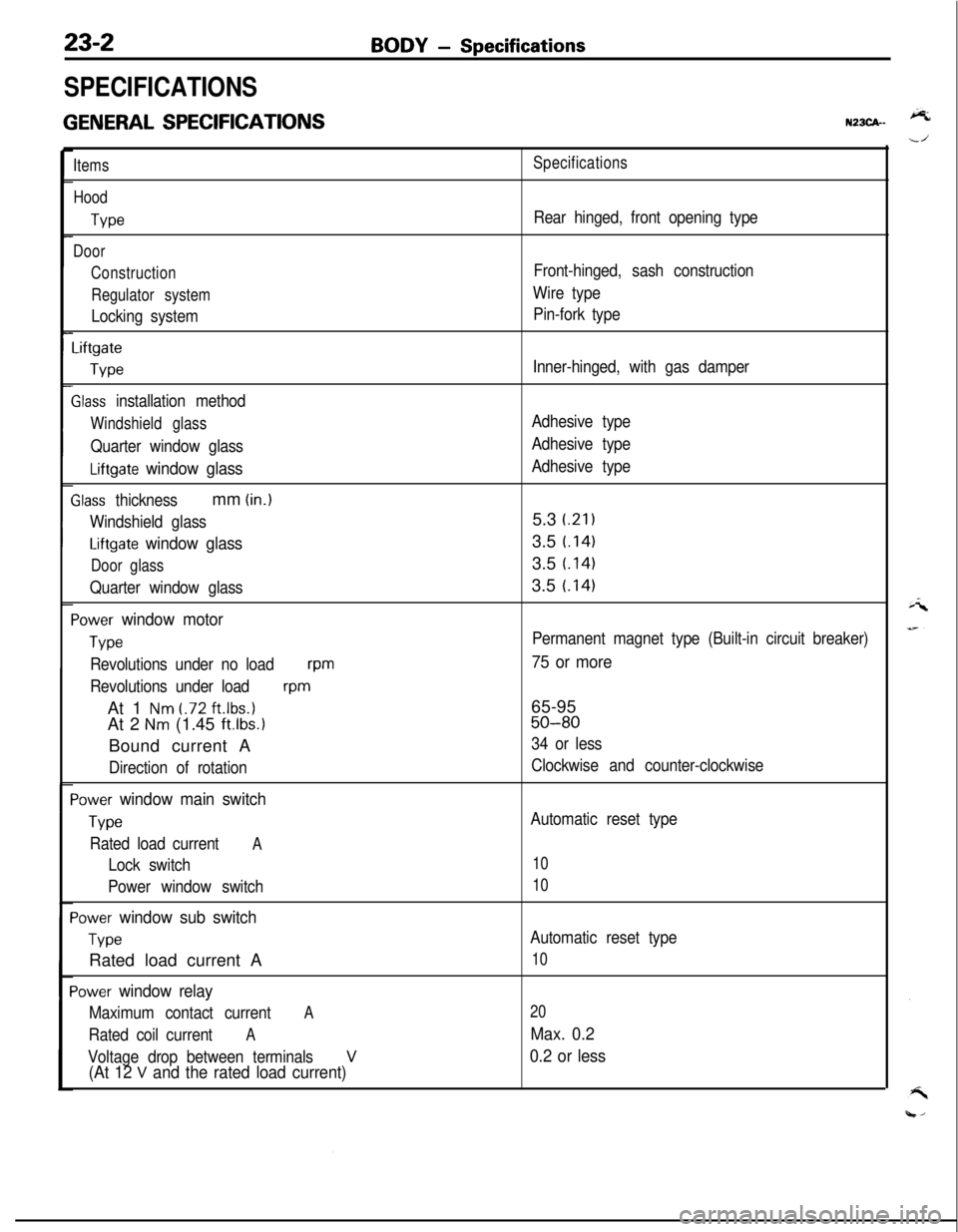
SPECIFICATIONS
GENERAL SPECIFICATIONS
BODY - Specifications
N23CA--
Items
Hood
We
Door
Construction
Regulator system
Locking system
Liftgate
We
Slass installation method
Windshield glass
Quarter window glass
Liftgate window glass
Zlass thicknessmm (in.)
Windshield glass
Liftgate window glass
Door glass
Quarter window glass
‘ower window motor
Type
Revolutions under no loadwm
Revolutions under load
wmAt 1
Nm t.72 ft.lbs.1At 2
Nm (1.45 ft.lbs.1Bound current A
Direction of rotation
‘ower window main switch
Type
Rated load currentA
Lock switch
Power window switch
‘ower window sub switch
TvwRated load current A
‘ower window relay
Maximum contact currentA
Rated coil currentA
Voltage drop between terminalsV(At 12 V and the rated load current)
Specifications
Rear hinged, front opening type
Front-hinged, sash construction
Wire type
Pin-fork type
Inner-hinged, with gas damper
Adhesive type
Adhesive type
Adhesive type5.3
i.21)3.5
t.1413.5
t.1413.5
t.141
Permanent magnet type (Built-in circuit breaker)
75 or more65-95
50-80
34 or less
Clockwise and counter-clockwise
Automatic reset type
10
10
Automatic reset type
10
20
Max. 0.2
0.2 or less
Page 1054 of 1216

23-10BODY - Troubleshooting
(PABBENGER’B BIDE)v 1
E-51
‘S
E-05
I2
m3458
POWER WINDOW
MOTOR
E-04
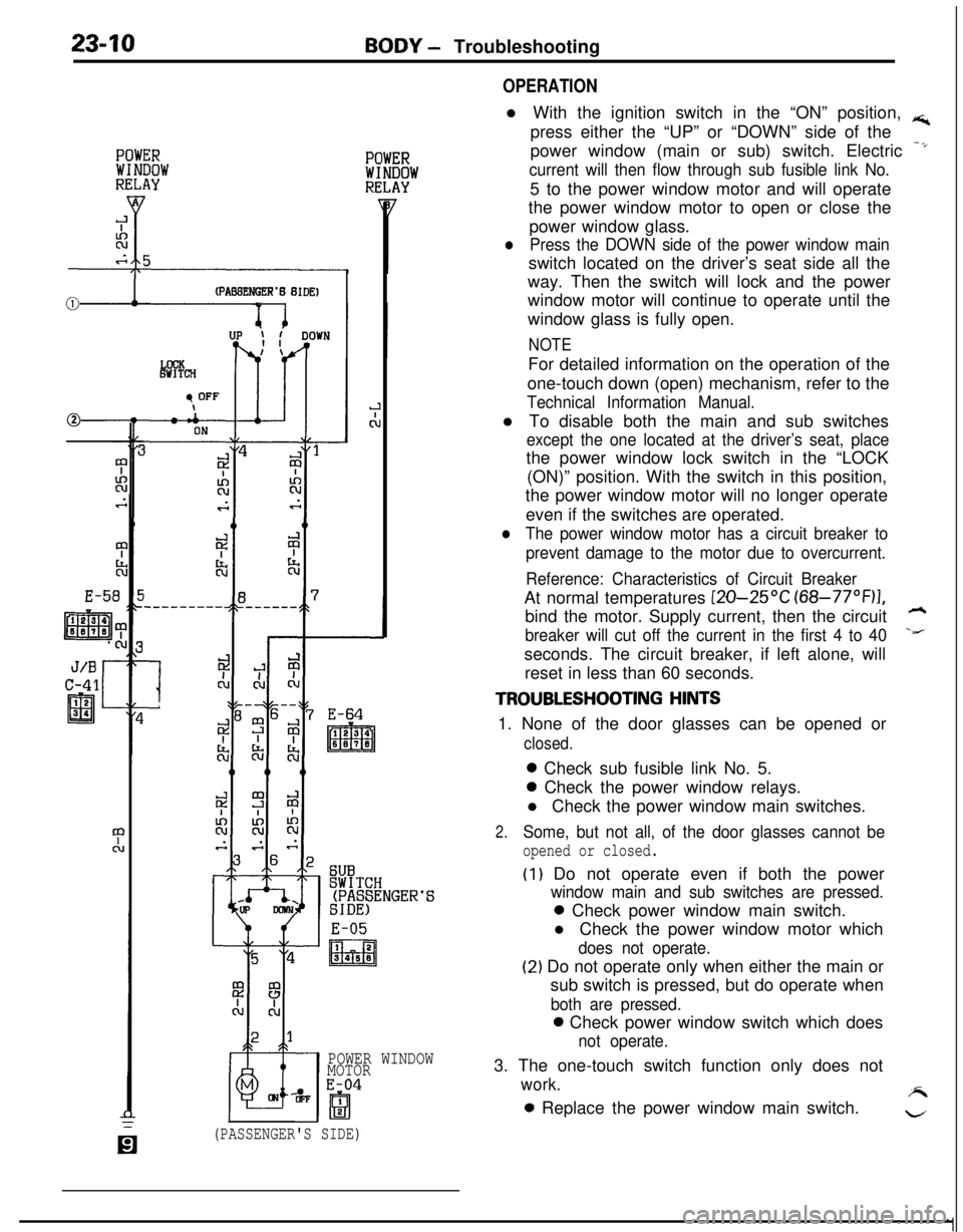
OPERATIONl With the ignition switch in the “ON” position,
rs;,press either the “UP” or “DOWN” side of the
power window (main or sub) switch. Electric
-*
current will then flow through sub fusible link No.5 to the power window motor and will operate
the power window motor to open or close the
power window glass.
lPress the DOWN side of the power window mainswitch located on the driver’s seat side all the
way. Then the switch will lock and the power
window motor will continue to operate until the
window glass is fully open.
NOTEFor detailed information on the operation of the
one-touch down (open) mechanism, refer to the
Technical Information Manual.l To disable both the main and sub switches
except the one located at the driver’s seat, placethe power window lock switch in the “LOCK
(ON)” position. With the switch in this position,
the power window motor will no longer operate
even if the switches are operated.
lThe power window motor has a circuit breaker to
prevent damage to the motor due to overcurrent.
Reference: Characteristics of Circuit BreakerAt normal temperatures
[ZO-25OC (68-77”F)I,bind the motor. Supply current, then the circuit
h
breaker will cut off the current in the first 4 to 40\&’seconds. The circuit breaker, if left alone, will
reset in less than 60 seconds.
TROUBLESHOOTING HINTS1. None of the door glasses can be opened or
closed.0 Check sub fusible link No. 5.0 Check the power window relays.
l Check the power window main switches.
2.Some, but not all, of the door glasses cannot be
opened or closed.
(I) Do not operate even if both the power
window main and sub switches are pressed.0 Check power window main switch.
l Check the power window motor which
does not operate.
(2) Do not operate only when either the main or
sub switch is pressed, but do operate when
both are pressed.0 Check power window switch which does
not operate.3. The one-touch switch function only does not
work.A0 Replace the power window main switch.
w
(PASSENGER'S SIDE)