compression ratio MITSUBISHI ECLIPSE 1991 Service Manual
[x] Cancel search | Manufacturer: MITSUBISHI, Model Year: 1991, Model line: ECLIPSE, Model: MITSUBISHI ECLIPSE 1991Pages: 1216, PDF Size: 67.42 MB
Page 27 of 1216
INTRODUCTION AND MASTER TROUBLESHOOTING - f~EEaZ% acld27
=r
9..
Items
TransaxleModel No.
Manual transaxle
Automatic transaxle
Clutch
Type
Chassis
TireFront suspension
TypeRear suspension
Type
Brake
Type
SteeringGear type
Gear ratio
Fuel tank
Capacity
2.0L DOHC Engine2.0L DOHC Engine2.0L DOHC Engine
(Non-Turbo)(FWD-Turbo)(AWD-Turbo)
F5M22F5M33W5M33
F4A22F4A33W4A33Dry-single disc
Dry-single discDry-single disc& diaphragm spring& diaphragm spring& diaphragm spring
P205/55R16 89HP205155R16 89VP205/55R16 89Vor 205/55R16 89Vor 205/55R16 88Vor 205/55R16 88Vor 205/55R16 88VIndependent strut
Independent strutIndependent strut
3-Link Torsion axle3-Link Torsion axleDouble wishbone
Front
Disc
DiscDisc
RearDisc
DiscDiscRack and pinion
Rack and pinionRack
,and pinion
03coccliters (gals.) 60 (16)
60 (16)60 (16)
)
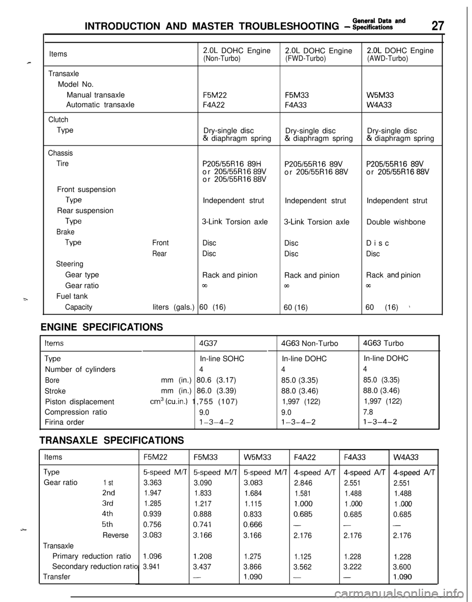
ENGINE SPECIFICATIONS
Items4G374G63 Non-Turbo4G63 Turbo
TypeIn-line SOHCIn-line DOHCIn-line DOHC
Number of cylinders
444
Boremm (in.) 80.6 (3.17)
85.0 (3.35)85.0 (3.35)
Strokemm (in.) 86.0 (3.39)
88.0 (3.46)88.0 (3.46)
Piston displacement
cm3 (cu.in.) 1,755 (107)1,997 (122)1,997 (122)Compression ratio
9.09.07.8Firina order
1-3-4-21-3-4-21-3-4-2
TRANSAXLE SPECIFICATIONS
ItemsF5M22F5M33W5M33F4A22F4A33W4A33
TypeGear ratio
1 st
2nd
3rd
4th
5th
Reverse
TransaxlePrimary reduction ratio
Secondary reduction
ratio
Transfer
5-speed M/T5-speed M/T
3.363
3.090
1.947
1.833
1.285
1.217
0.939
0.888
0.756
0.741
3.0833.166
5speed M/T4-speed A/T4-speed AIT
3.083
2.8462.551
1.6841.5811.488
1.115
1.0001 .ooo
0.8330.6850.685
0.666--
3.166
2.1762.176
Qspeed AIT
2.551
1.488
1 .ooo
0.685
-
2.176
1.096
3.9411.2081.275
1.1251.2281.228
3.4373.866
3.5623.222
3.600
-1.090--1.090
Page 30 of 1216
30INTRODUCTION AND MASTER TROUBLESHOOTING - Master Troubleshooting
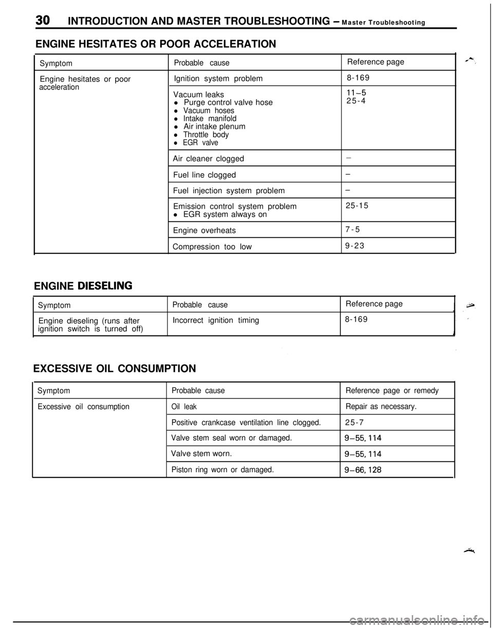
ENGINE HESITATES OR POOR ACCELERATION
SymptomEngine hesitates or poor
accelerationProbable causeIgnition system problem
Vacuum leaks
l Purge control valve hose
l Vacuum hosesl Intake manifoldl Air intake plenum
l Throttle bodyl EGR valveReference page
8-169
11-525-4
Air cleaner clogged
Fuel line clogged
Fuel injection system problem
Emission control system problem
l EGR system always on
Engine overheats
Compression too low
-
-
-25-15
7-5
9-23
ENGINE
DIESELING
SymptomEngine dieseling (runs after
ignition switch is turned off)Probable causeIncorrect ignition timingReference page
8-169
EXCESSIVE OIL CONSUMPTION
Symptom
Excessive oil consumptionProbable cause
Oil leak
Positive crankcase ventilation line clogged.
Valve stem seal worn or damaged.Valve stem worn.
Piston ring worn or damaged.Reference page or remedy
Repair as necessary.25-7
g-55.114
g-55.114
g-66,128
Page 142 of 1216
5-2BRAKES - SDecifications
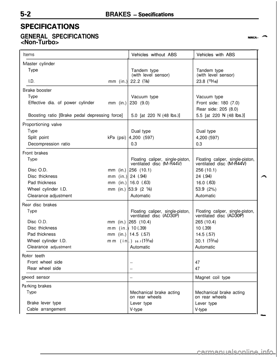
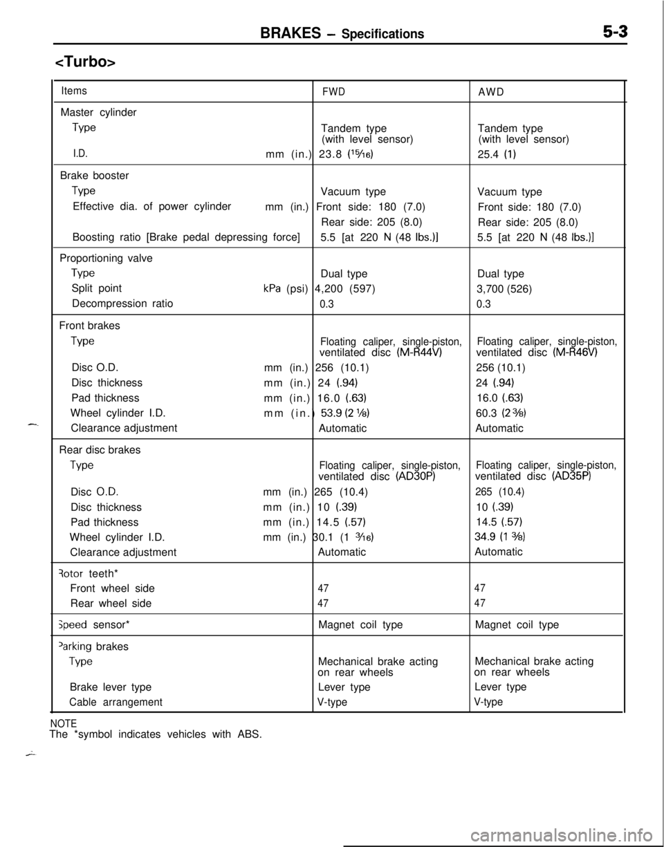
SPECIFICATIONS
GENERAL SPECIFICATIONS
NO!iCA-- -
ItemsItems
NNVehicles without ABS Vehicles without ABSVehicles with ABS Vehicles with ABS
BIBI
PlPl
Fr Frlaster cylinder
TypeTandem typeTandem type
(with level sensor)(with level sensor)
I.D.mm (in.) 22.2 (7/8)23.8 (‘%6)rake booster
TypeVacuum typeVacuum type
Effective dia. of power cylinder
mm (in.) 230 (9.0)Front side: 180 (7.0)
Rear side: 205 (8.0)
Boosting ratio [Brake pedal depressing force]
5.0 [at 220
N (48 Ibs.)]5.5 [at 220 N (48 Ibs.)]
.oportioning valve
TypeDual typeDual type
Split point
kPa (psi) 4,200 (597)
4,200 (597)
Decompression ratio
0.3
0.3ont brakes
TypeFloating caliper, single-piston,ventilated disc (M-R44V)Floating caliper, single-piston,ventilated disc (M-R44V)Disc O.D.
mm (in.) 256 (10.1)256 (10.1)
Disc thickness
mm (in.) 24
(.94)24 (.94)Pad thicknessmm (in.) 16.0 (63)
16.0
(.63)Wheel cylinder I.D.
mm (in.) 53.9 (2
l/8)53.9 (2%)
Clearance adjustmentAutomaticAutomatic
3ar disc brakes
TypeFloating caliper, single-piston,Floating caliper, single-piston,ventilated disc (AD30P)ventilated disc (AD30P)Disc
O.D.mm (in.) 265 (10.4)265 (10.4)
Disc thickness
mm (in.)
10 (39)10 i.39)Pad thickness
mm (in.) 14.5 (57)
14.5 (57)
Wheel cylinder I.D.
mm (in.) 30.1
(1 3/16)30.1 (1 346)Clearance adjustment
AutomaticAutomatic
)tor teeth
Front wheel side
-47Rear wheel side
-47
leed sensor-Magnet coil type
rking brakes
TypeMechanical brake actingMechanical brake acting
on rear wheelson rear wheels
Brake lever type
Lever type
Lever type
Cable arrangement
V-type
V-type
Rc Rc
SP SP
Pa Pa
Page 143 of 1216
BRAKES - Specifications5-3
ItemsFWDAWDMaster cylinder
TypeTandem type
(with level sensor)Tandem type
(with level sensor)
I.D.mm (in.) 23.8 (‘%a)25.4 (1)Brake booster
TypeVacuum type
Vacuum type
Effective dia. of power cylinder
mm (in.) Front side: 180 (7.0)
Front side: 180 (7.0)
Rear side: 205 (8.0)
Rear side: 205 (8.0)
Boosting ratio [Brake pedal depressing force]
5.5 [at 220
N (48 Ibs.)]5.5 [at 220 N (48 Ibs.)]Proportioning valve
TypeDual typeDual type
Split point
kPa (psi) 4,200 (597)
3,700 (526)
Decompression ratio
0.30.3Front brakes
TypeFloating caliper, single-piston,Floating caliper, single-piston,ventilated disc (M-R44V)ventilated disc (M-R46V)Disc O.D.
mm (in.) 256 (10.1)256 (10.1)
Disc thickness
mm (in.) 24
(.94)24 (.94)Pad thickness
mm (in.) 16.0
(.63)16.0 (.63)Wheel cylinder I.D.
mm (in.)
53.9 (2 ‘16)60.3 (23%3)Clearance adjustment
AutomaticAutomatic
Rear disc brakes
TypeFloating caliper, single-piston,Floating caliper, single-piston,ventilated disc (AD30P)ventilated disc (AD35P)Disc
O.D.mm (in.) 265 (10.4)265 (10.4)Disc thicknessmm (in.) 10
(.39)10 f.39)Pad thicknessmm (in.) 14.5
(.57)14.5 (.57)Wheel cylinder I.D.mm (in.) 30.1 (1
3/16)34.9 (1 3h)Clearance adjustmentAutomaticAutomatic
qotor teeth*
Front wheel side
4747Rear wheel side
4747
speed sensor*Magnet coil typeMagnet coil type‘arking brakes
TypeMechanical brake actingMechanical brake acting
on rear wheelson rear wheels
Brake lever typeLever typeLever type
Cable arrangementV-typeV-type
NOTEThe *symbol indicates vehicles with ABS.
Page 285 of 1216
9-1
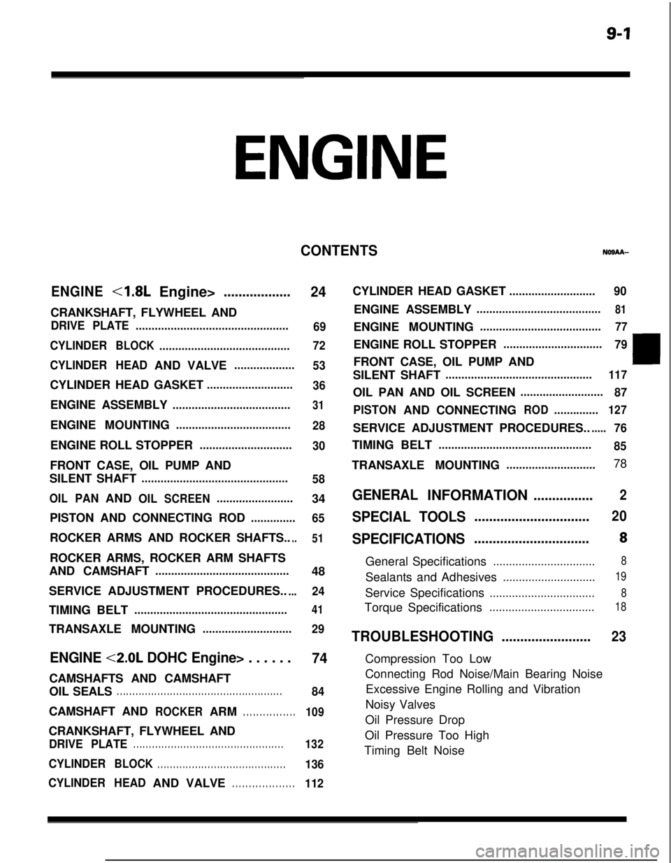
ENGINE
CONTENTSNOSAA-
ENGINE<1.8L
Engine>..................
24CRANKSHAFT, FLYWHEEL AND
DRIVE PLATE................................................
69
CYLINDER
BLOCK.........................................72
CYLINDERHEADANDVALVE
...................
53CYLINDER HEAD GASKET
...........................
36ENGINE ASSEMBLY
.....................................31ENGINE MOUNTING
....................................
28ENGINE ROLL STOPPER
.............................
30FRONT CASE, OIL PUMP AND
SILENT SHAFT
..............................................
58
OILPANANDOILSCREEN........................34
PISTON AND CONNECTING ROD
..............
65ROCKER ARMS AND ROCKER SHAFTS..
..51ROCKER ARMS, ROCKER ARM SHAFTS
AND CAMSHAFT
..........................................48
SERVICE ADJUSTMENT PROCEDURES..
...24TIMING BELT
................................................41TRANSAXLE MOUNTING
............................
29
ENGINE <2.0L DOHC Engine> . . . . . .
74CAMSHAFTS AND CAMSHAFT
OIL SEALS
. . . . . . . . . . . . . . . . . . . . . . . . . . . . . . . . . . . . . . . . . . . . . . . . . . . . .84CAMSHAFTAND
ROCKERARM. . . . . . . . . . . . . . . .109CRANKSHAFT, FLYWHEEL AND
DRIVE PLATE. . . . . . . . . . . . . . . . . . . . . . . . . . . . . . . . . . . . . . . . . . . . . . . .132
CYLINDERBLOCK. . . . . . . . . . . . . . . . . . . . . . . . . . . . . . . . . . . . . . . . .136
CYLINDERHEADANDVALVE
. . . . . . . . . . . . . . . . . . .112CYLINDER HEAD GASKET
...........................90ENGINE ASSEMBLY
.......................................81ENGINE MOUNTING
......................................77ENGINE ROLL STOPPER
...............................
79FRONT CASE, OIL PUMP AND
SILENT SHAFT
..............................................117OIL PAN AND OIL SCREEN
..........................
87
PISTONANDCONNECTING
ROD..............127SERVICE ADJUSTMENT PROCEDURES..
.....76TIMING BELT
................................................
85TRANSAXLE MOUNTING
............................78
GENERALINFORMATION................2
SPECIAL TOOLS...............................20
SPECIFICATIONS...............................8General Specifications
................................8Sealants and Adhesives
.............................19Service Specifications
.................................8Torque Specifications
.................................18
TROUBLESHOOTING........................23Compression Too Low
Connecting Rod Noise/Main Bearing Noise
Excessive Engine Rolling and Vibration
Noisy Valves
Oil Pressure Drop
Oil Pressure Too High
Timing Belt Noise
Page 292 of 1216
9-8ENGINE - Specifications
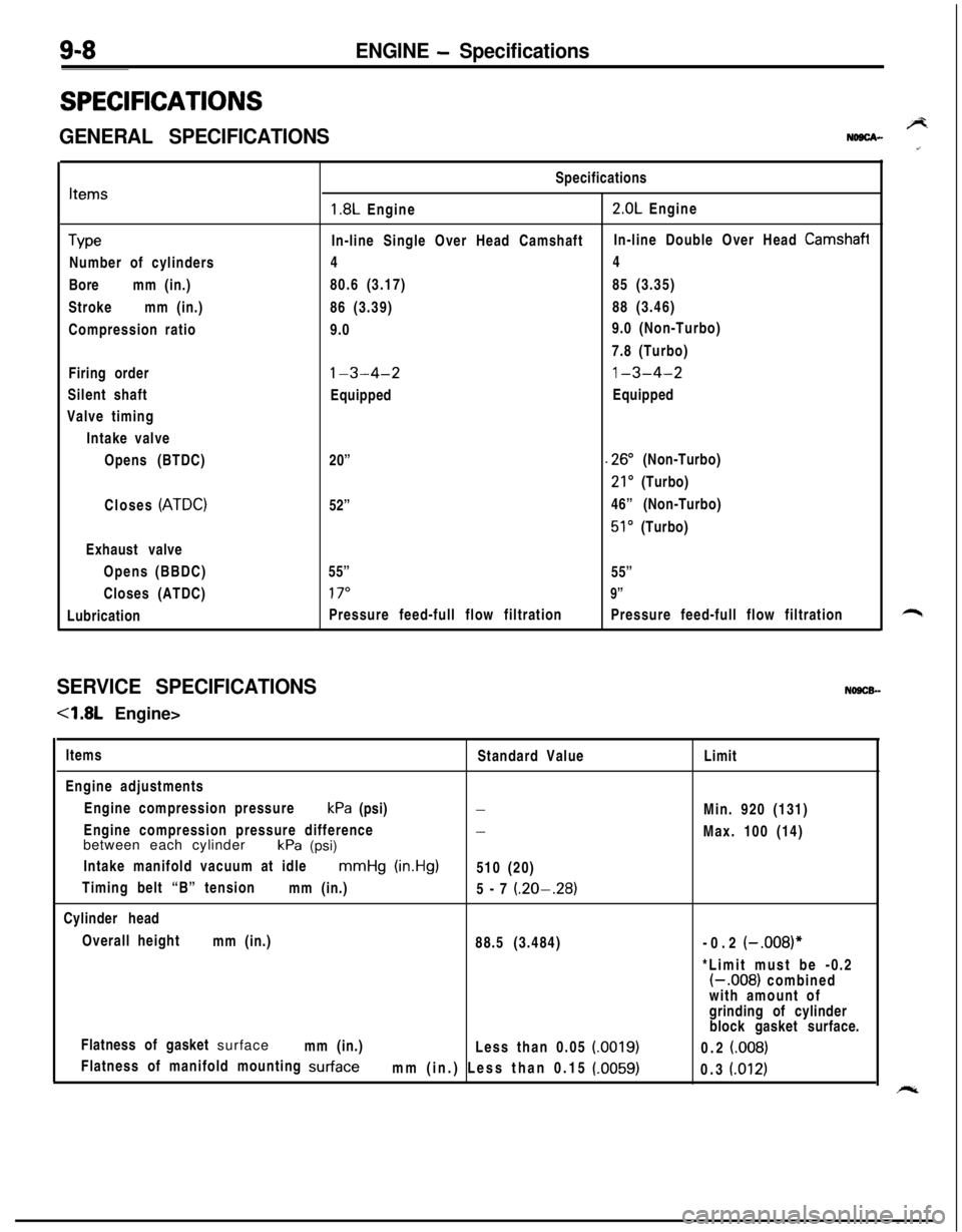
SPECIFICATIONS
GENERAL SPECIFICATIONSBNDBCA-
Items
TypeNumber of cylinders
Boremm (in.)
Strokemm (in.)
Compression ratio
Firing order
Silent shaft
Valve timing
Intake valve
Opens (BTDC)
Closes
(ATDC)Exhaust valve
Opens (BBDC)
Closes (ATDC)
LubricationSpecifications
1.8L Engine2.0L Engine
In-line Single Over Head CamshaftIn-line Double Over Head
Camshafi44
80.6 (3.17)85 (3.35)
86 (3.39)88 (3.46)
9.09.0 (Non-Turbo)
7.8 (Turbo)
l-3-4-21-3-4-2EquippedEquipped
20”
.26” (Non-Turbo)
21’ (Turbo)
52”46” (Non-Turbo)
51’ (Turbo)
55”
55”
17”9”Pressure feed-full flow filtrationPressure feed-full flow filtration
SERVICE SPECIFICATIONSNOSCB-
-4.8L Engine>
Items
Standard Value
Engine adjustments
Engine compression pressurekPa (psi)
-Engine compression pressure difference
-between each cylinder
kPa (psi)
Intake manifold vacuum at idle
mmHg (in.Hg)510 (20)
Timing belt “B” tension
mm (in.)
5-7
(.20-.28)Cylinder head
Overall height
mm (in.)
88.5 (3.484)
Flatness of gasket surface
mm (in.)
Less than 0.05
(0019)Flatness of manifold mounting
surfacemm (in.) Less than 0.15 (.0059)Limit
Min. 920 (131)
Max. 100 (14)
-0.2
(-.008)**Limit must be -0.2
(-.008) combined
with amount of
grinding of cylinder
block gasket surface.
0.2
(008)0.3
(.012)
Page 307 of 1216
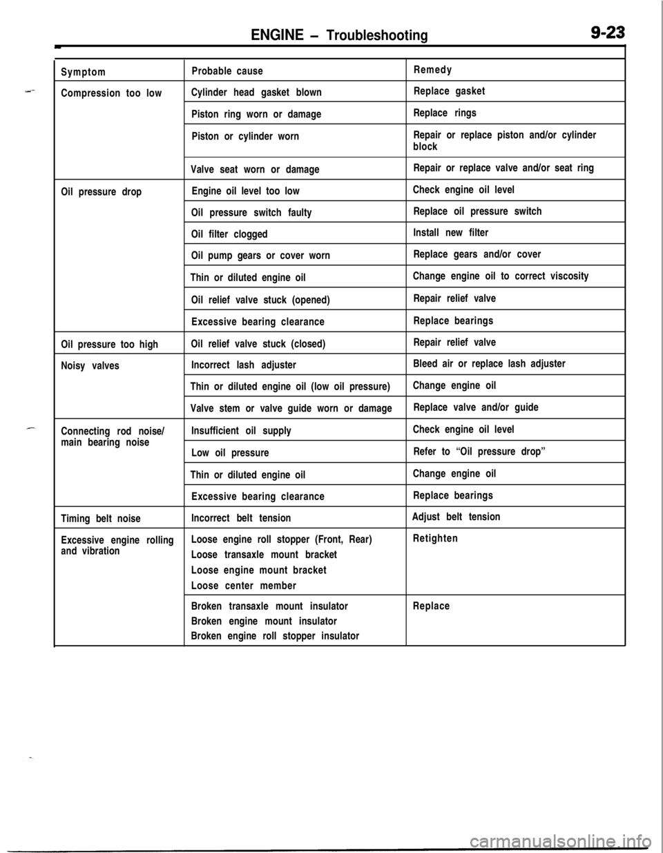
ENGINE - Troubleshooting9-23
--Symptom
Compression too lowProbable cause
Cylinder head gasket blown
Piston ring worn or damage
Piston or cylinder wornRemedy
Replace gasket
Replace rings
Repair or replace piston and/or cylinder
block
Valve seat worn or damageRepair or replace valve and/or seat ring
Oil pressure dropEngine oil level too lowCheck engine oil level
Oil pressure switch faultyReplace oil pressure switch
Oil filter cloggedInstall new filter
Oil pump gears or cover wornReplace gears and/or cover
Thin or diluted engine oilChange engine oil to correct viscosity
Oil relief valve stuck (opened)Repair relief valve
Excessive bearing clearanceReplace bearings
Oil pressure too highOil relief valve stuck (closed)Repair relief valve
Noisy valvesIncorrect lash adjusterBleed air or replace lash adjuster
Thin or diluted engine oil (low oil pressure)Change engine oil
Valve stem or valve guide worn or damageReplace valve and/or guide
Connecting rod noise/Insufficient oil supplyCheck engine oil level
main bearing noise
Low oil pressureRefer to “Oil pressure drop”
Thin or diluted engine oilChange engine oil
Excessive bearing clearanceReplace bearings
Timing belt noiseIncorrect belt tensionAdjust belt tension
Excessive engine rollingLoose engine roll stopper (Front, Rear)Retighten
and vibration
Loose transaxle mount bracket
Loose engine mount bracket
Loose center member
Broken transaxle mount insulatorReplace
Broken engine mount insulator
Broken engine roll stopper insulator
Page 1158 of 1216
24-14 HEATERS AND AIR CONDITIONING - Service Adjustment Procedures
-Discharge
w-w
SuctiongaugeDischalgauge
2OUO306
SuctiongaugeDischargegauge
2OUO307--
MAGNETIC CLUTCH(I) Disconnect the wiring to the magnetic clutch.
(2) Connect battery (+) voltage directly to the wiring for the
magnetic clutch.
,”(3) If the magnetic clutch is normal, there will be a “click”. If
the pulley and armature do not make contact (“click”),
there is a malfunction.
Using an ohmmeter, measure the resistance of the clutch
coil between the clutch lead wire and ground.
Standard resistance: 3.4-3.8
Q at 20°C (88°F)If resistance is not as specified, replace the coil.
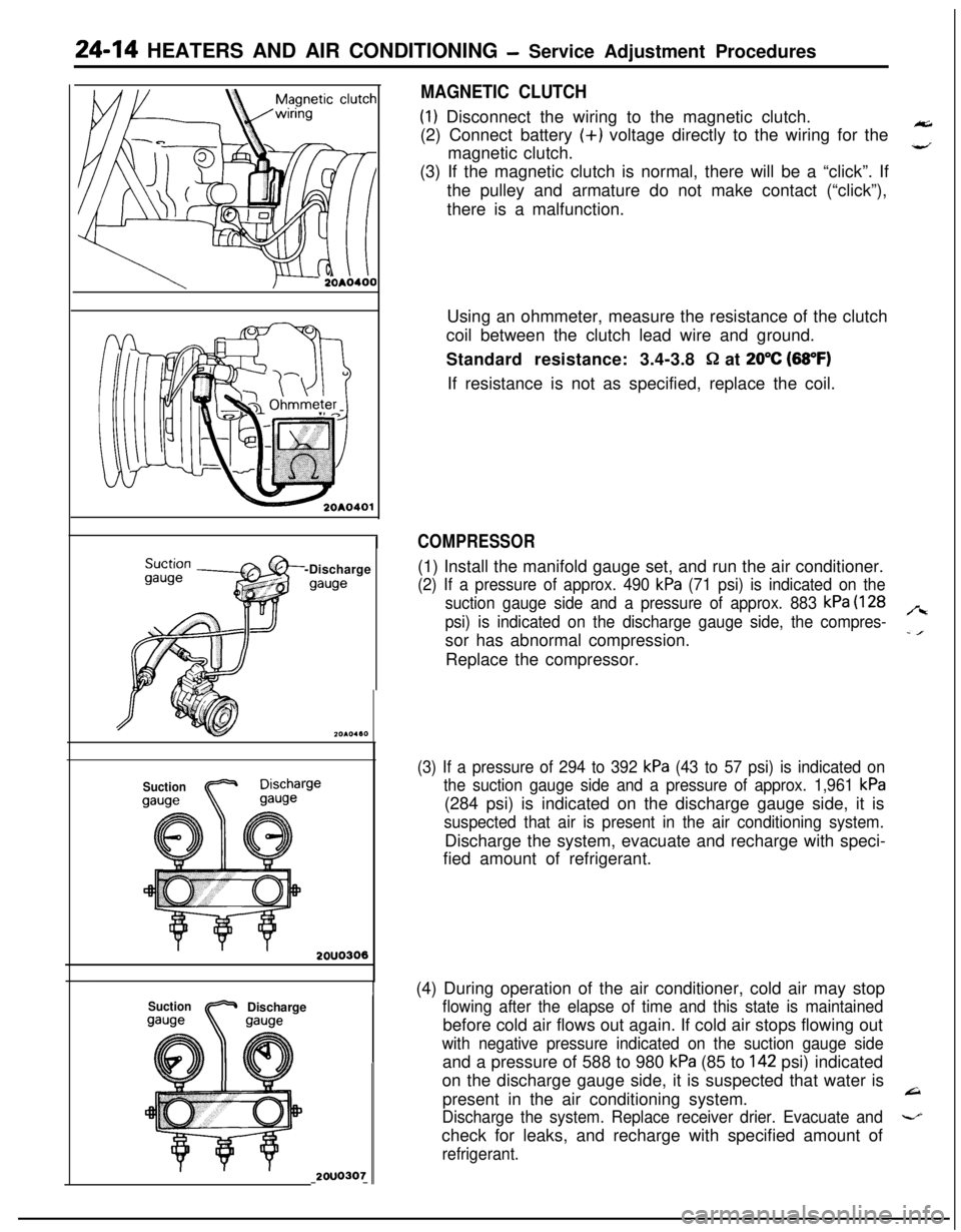
COMPRESSOR(1) Install the manifold gauge set, and run the air conditioner.
(2) If a pressure of approx. 490 kPa (71 psi) is indicated on the
suction gauge side and a pressure of approx. 883
kPa (128
psi) is indicated on the discharge gauge side, the compres-
,“ssor has abnormal compression.
-IReplace the compressor.
(3) If a pressure of 294 to 392 kPa (43 to 57 psi) is indicated on
the suction gauge side and a pressure of approx. 1,961
kPa(284 psi) is indicated on the discharge gauge side, it is
suspected that air is present in the air conditioning system.Discharge the system, evacuate and recharge with speci-
fied amount of refrigerant.
(4) During operation of the air conditioner, cold air may stop
flowing after the elapse of time and this state is maintainedbefore cold air flows out again. If cold air stops flowing out
with negative pressure indicated on the suction gauge sideand a pressure of 588 to 980
kPa (85 to 142 psi) indicated
on the discharge gauge side, it is suspected that water is
present in the air conditioning system.
L=I
Discharge the system. Replace receiver drier. Evacuate and-check for leaks, and recharge with specified amount of
refrigerant.