coolant temperature MITSUBISHI ECLIPSE 1991 Service Manual
[x] Cancel search | Manufacturer: MITSUBISHI, Model Year: 1991, Model line: ECLIPSE, Model: MITSUBISHI ECLIPSE 1991Pages: 1216, PDF Size: 67.42 MB
Page 14 of 1216
I4INTRODUCTION AND MASTER TROUBLESHOOTING - Precautions before Service
mm (In.1smo59
PARTSWhen replacing parts, use MOPAR genuine parts.
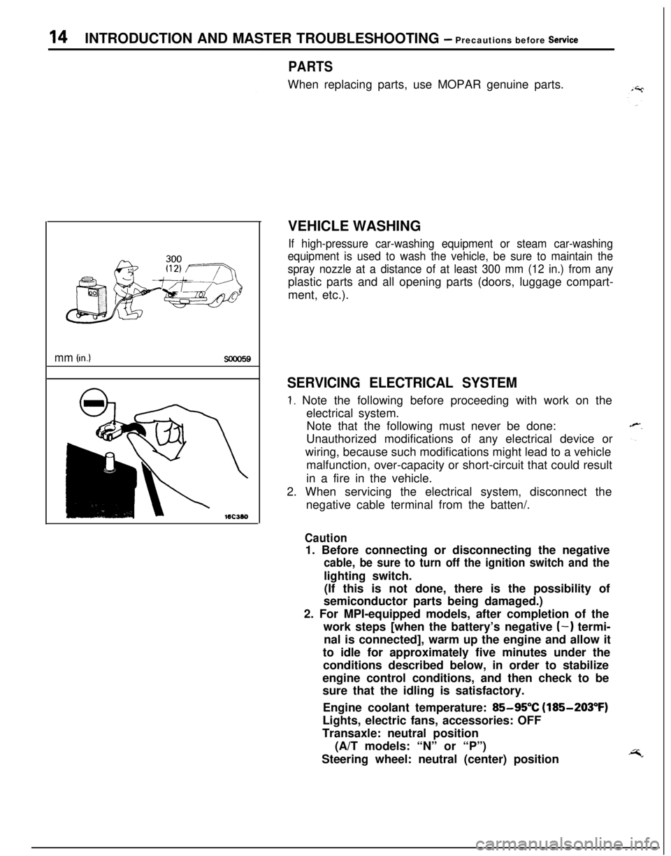
VEHICLE WASHING
If high-pressure car-washing equipment or steam car-washing
equipment is used to wash the vehicle, be sure to maintain the
spray nozzle at a distance of at least 300 mm (12 in.) from anyplastic parts and all opening parts (doors, luggage compart-
ment, etc.).
SERVICING ELECTRICAL SYSTEM
1. Note the following before proceeding with work on the
electrical system.
Note that the following must never be done:
Unauthorized modifications of any electrical device or
wiring, because such modifications might lead to a vehicle
malfunction, over-capacity or short-circuit that could result
in a fire in the vehicle.
2. When servicing the electrical system, disconnect the
negative cable terminal from the batten/.
Caution1. Before connecting or disconnecting the negative
cable, be sure to turn off the ignition switch and thelighting switch.
(If this is not done, there is the possibility of
semiconductor parts being damaged.)
2. For MPI-equipped models, after completion of the
work steps [when the battery’s negative
(-) termi-
nal is connected], warm up the engine and allow it
to idle for approximately five minutes under the
conditions described below, in order to stabilize
engine control conditions, and then check to be
sure that the idling is satisfactory.
Engine coolant temperature:
85-95°C (185-203°F)
Lights, electric fans, accessories: OFF
Transaxle: neutral position
(A/T models: “N” or “P”)
Steering wheel: neutral (center) position
Page 38 of 1216
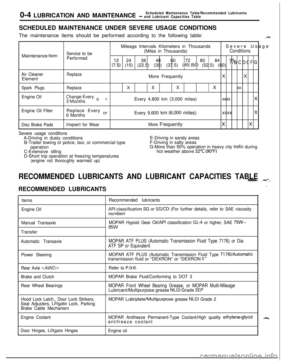
0-4 LUBRICATION AND MAINTENANCEScheduled Maintenance Table/Recommended Lubricants- and Lubricant Capacities TableSCHEDULED MAINTENANCE UNDER SEVERE USAGE CONDITIONS
The maintenance items should be performed according to the following table:
F.Mileage Intervals Kilometers in ThousandsSevere Usage
Service to be(Miles in Thousands)ConditionsMaintenance
Item
Performed24 36 48 60 72 80 84 96
(:,:) (15) (22.5) (30) (37.5) (45) (50) (52.5) (60) * B ’ D E F G
Air CleanerReplaceElementMore FrequentlyXX
Spark PlugsReplace
XXXx xx
Engine Oil$$~~~h~vev orEvery 4,800 km (3,000 miles)xxxx x
Engine Oil FilterReplace Every or6 MonthsEvery 9,600 km (6,000 miles)xxxx x
Disc Brake PadsInspect for WearMore FrequentlyXX
Severe usage conditionsA-Driving in dusty conditionsE-Driving in sandy areas
B-Trailer towing or police, taxi, or commercial typeF-Driving in salty areas
operationG-More than 50% operation in heavy city trafic during
C-Extensive idlinghot weather above 32°C (90°F)D-Short trip operation at freezing temperatures
(engine not thoroughly warmed up)
RECOMMENDED LUBRICANTS AND LUBRICANT CAPACITIES TABLENOONA- --z.
RECOMMENDED LUBRICANTS
Items
Engine Oil
Manual Transaxle
TransferRecommended lubricantskF&cesisification
SG or SG/CD (For further details, refer to SAE viscosity
MOPAR Hypoid Gear
Oil/API classification GL4 or higher, SAE 75W-85W
Automatic TransaxleMOPAR ATF PLUS (Automatic Transmission Fluid Type 7176) or Dia
ATF SP or Equivalent
Power SteeringMOPAR ATF PLUS (Automatic Transmission Fluid Type 7176VAutomatictransmission fluid or “DEXRON” or “DEXRON II”
Rear Axle
Brake and Clutch
Rear Wheel BearingsRefer to
P.O-6.
MOPAR Brake Fluid/Conforming to DOT 3
MOPAR Front Wheel Bearing Grease, or MOPAR Multi-MileageLubricant/Multipurpose grease NLGI Grade 2EP
Hood Lock Latch,, Door Lock Strikers,
Seat Adjusters, Lrftgate Lock, Parking
Brake Cable MechanismMOPAR Lubriplate/Multipurpose grease NLGI Grade 2
Engine CoolantMOPAR Antifreeze Permanent-Type Coolant/High quality
ethylene-glycolantifreeze coolant
Door Hinges, Liftgate Hinges
Engine oil
/
N
Page 39 of 1216
LUBRICATION AND MAINTENANCE - Recommended Lubrie’ntsand Lubrtcant Capacttles Table
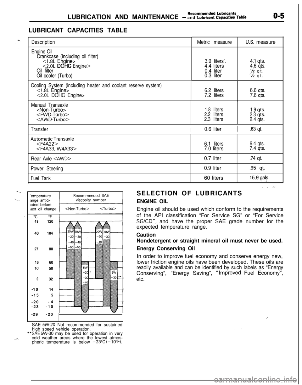
LUBRICANT CAPACITIES TABLE
Description
Engine Oil Engine Oil
Crankcase (including oil filter) Crankcase (including oil filter)
<1.8L Engine><1.8L Engine><2.0L DOHC Engine><2.0L DOHC Enaine>Oil filter Oil filter
Oil cooler (Turbo) Oil cooler (Turbo)
Metric measureU.S. measure
3.9 liters’.4.4 liters
0.4 liter
0.3 liter
4.‘1 qts.4.6 qts.
‘h qt.Y2 qt.
Cooling System (including heater and coolant reserve system)
<2.0L DOHC Engine>6.2 liters
7.2 liters6.6
qts.
7.6 qts.
Manual Transaxle
1.8liters1.9qts.2.2liters2.3qts.
2.3liters
2.4qts.
Transfer
I0.6 literI.63 qt.
Au:oFmqaAtF2pnsaxle
Rear Axle
Power Steering
Fuel Tank
"C“F4912040
104
27
80
1660
1050
032-10
14-15
5-20-4
-23-10
-29-20
6.1 liters6.4 qts.
7.0 liters7.4 qts.
0.7 liter.74 qt.
0.9 liter.95 sf.60 liters
15.9 gal?.
’ ~ “.SELECTION OF LUBRICANTS
ENGINE OIL
Engine oil should be used which conform to the requirements
of the API classification “For Service SG” or “For Service
SGKD”, and have the proper SAE grade number for the
expected temperature range.
Caution
Nondetergent or straight mineral oil must never be used.
Energy Conserving Oil
In order to improve fuel economy and conserve energy new,
lower friction engine oils have been developed. These oils are
readily available and can be identified by such labels as “EnergyConserving”,“Energy Saving”,“Improved Fuel Economy”,
etc.
/”SAE
5W-20 Not recommended for sustained
high speed vehicle operation.**SAE
5W-30 may be used for operation in very
cold weather areas where the lowest atmos-
pheric temperature is below
-23°C (-10°F).
Page 40 of 1216
O-6LUBRICATION AND MAINTENANCE - Capacities TableRecommended Lubricants and Lubricant
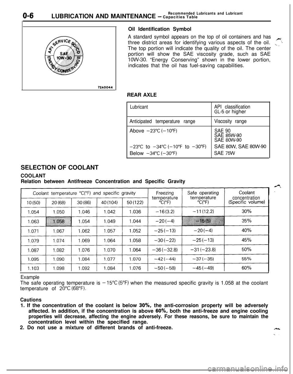
72A0044Oil Identification Symbol
A standard symbol appears on the top of oil containers and hasthree district areas for identifying various aspects of the oil.
The top portion will indicate the quality of the oil. The center
portion will show the SAE viscosity grade, such as SAE
IOW-30. “Energy Conserving” shown in the lower portion,
indicates that the oil has fuel-saving capabilities.
REAR AXLE
LubricantAPI classification
GL-5 or higher
Anticipated temperature rangeViscosity rangeAbove -23°C
(-10°F)SAE 90SAE 85W-90SAE 8OW-90
-23°C to -34°C (-10°F to -30°F)SAE 8OW, SAE 8OW-90Below -34°C
(-30°F)SAE 75WSELECTION OF COOLANT
COOLANTRelation between Antifreeze Concentration and Specific Gravity
concentration
ExampleThe safe operating temperature is
- 15°C (5°F) when the measured specific gravity is 1.058 at the coolant
temperature of
20°C (68°F).
Cautions1. If the concentration of the coolant is below 30%, the anti-corrosion property will be adversely
affected. In addition, if the concentration is above 60%, both the anti-freeze and engine cooling
properties will decrease, affecting the engine adversely. For these reasons, be sure to maintain theconcentration level within the specified range.
2. Do not use a mixture of different brands of anti-freeze.
Page 46 of 1216
LUBRICATION AND MAINTENANCE - Maintenance Service
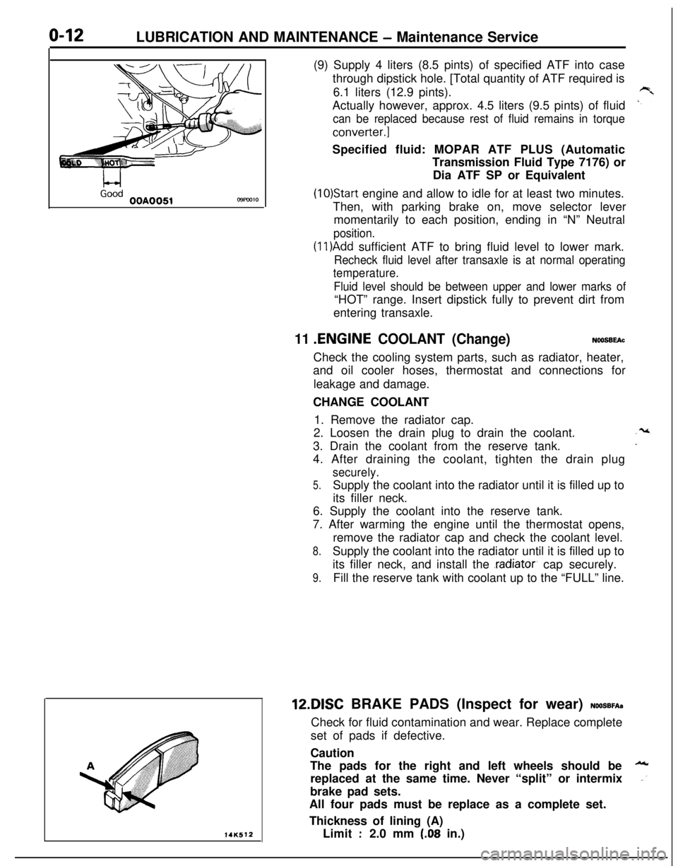
L-4GoodOOA0051C9FW1014K512(9) Supply 4 liters (8.5 pints) of specified ATF into case
through dipstick hole. [Total quantity of ATF required is
6.1 liters (12.9 pints).
Actually however, approx. 4.5 liters (9.5 pints) of fluid
can be replaced because rest of fluid remains in torque
converter.]Specified fluid: MOPAR ATF PLUS (Automatic
Transmission Fluid Type 7176) or
Dia ATF SP or Equivalent
(10)Start engine and allow to idle for at least two minutes.
Then, with parking brake on, move selector lever
momentarily to each position, ending in “N” Neutral
position.
(1 l)Add sufficient ATF to bring fluid level to lower mark.
Recheck fluid level after transaxle is at normal operating
temperature.
Fluid level should be between upper and lower marks of“HOT” range. Insert dipstick fully to prevent dirt from
entering transaxle.
11 .ENGINE COOLANT (Change)NOOSBEAcCheck the cooling system parts, such as radiator, heater,
and oil cooler hoses, thermostat and connections for
leakage and damage.
CHANGE COOLANT
1. Remove the radiator cap.
2. Loosen the drain plug to drain the coolant.
3. Drain the coolant from the reserve tank.
4. After draining the coolant, tighten the drain plug
securely.
5.Supply the coolant into the radiator until it is filled up to
its filler neck.
6. Supply the coolant into the reserve tank.
7. After warming the engine until the thermostat opens,
remove the radiator cap and check the coolant level.
8.Supply the coolant into the radiator until it is filled up to
its filler neck, and install the
.radiator, cap securely.
9.Fill the reserve tank with coolant up to the “FULL” line.12DISC BRAKE PADS (Inspect for wear)
NOOSBFA~Check for fluid contamination and wear. Replace complete
set of pads if defective.
Caution
The pads for the right and left wheels should be
replaced at the same time. Never “split” or intermix
brake pad sets.
All four pads must be replace as a complete set.
Thickness of lining (A)
Limit
:2.0 mm (.08 in.)
Page 249 of 1216
7-l
COOLING
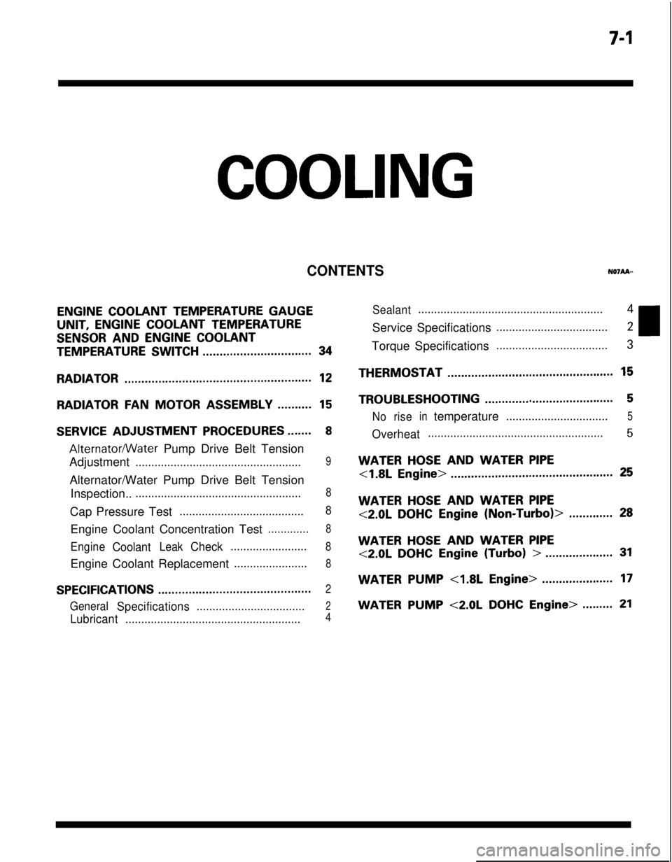
CONTENTS
ENGINE COOLANT TEMPERATURE GAUGEUNIT,
ENGINE COOLANT TEMPERATURE
SENSOR AND ENGINE COOLANT
TEMPERATURE SWITCH................................34
RADIATOR.......................................................12
RADIATORFANMOTOR ASSEMBLY..........15
SERVICE ADJUSTMENT PROCEDURES.......8
Alternatormater Pump Drive Belt Tension
Adjustment
....................................................9Alternator/Water Pump Drive Belt Tension
Inspection..
....................................................8Cap Pressure Test
.......................................8Engine Coolant Concentration Test
.............8
EngineCoolantLeakCheck........................8Engine Coolant Replacement
.......................8
SPECIFICATIONS.............................................2
GeneralSpecifications..................................2
Lubricant.......................................................4
Sealant..........................................................4Service Specifications
...................................2Torque Specifications
...................................3THERMOSTAT
.................................................15
TROUBLESHOOTING......................................5
Noriseintemperature................................5
Overheat.......................................................5
WATER HOSE AND WATER PIPE
<1.8L Engine>................................................25
WATER HOSE AND WATER PIPE
<2.0LDOHCEngine(Non-Turbo)>.............28
WATER HOSE AND WATER PIPE
<2.0LDOHCEngine(Turbo)>....................31
WATERPUMP<1.8LEngine>.....................17
WATER PUMP <2.0L DOHC Engine>.........21
Page 250 of 1216
7-2COOLING - Specifications
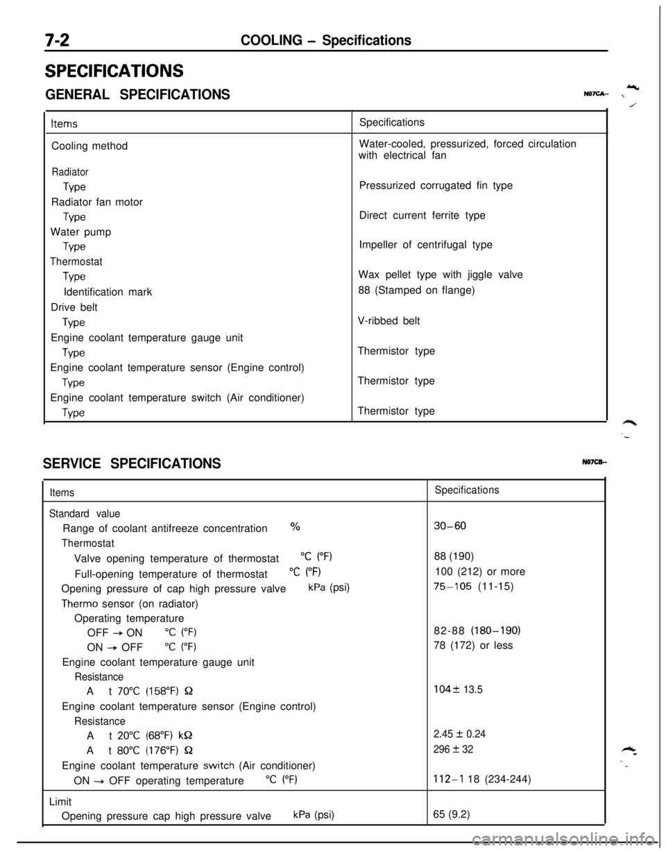
SPECIFICATIONS
GENERAL SPECIFICATIONSIcNQ7cA- I
ItemsCooling method
Radiator
TypeRadiator fan motor
TypeWater pump
Type
Thermostat
TypeIdentification mark
Drive belt
TypeEngine coolant temperature gauge unit
WeEngine coolant temperature sensor (Engine control)
TypeEngine coolant temperature switch (Air conditioner)
WeSpecifications
Water-cooled, pressurized, forced circulation
with electrical fan
Pressurized corrugated fin type
Direct current ferrite type
Impeller of centrifugal type
Wax pellet type with jiggle valve
88 (Stamped on flange)
V-ribbed belt
Thermistor type
Thermistor type
Thermistor type
SERVICE SPECIFICATIONSN07CB.-
Items
Standard valueRange of coolant antifreeze concentration
%
ThermostatValve opening temperature of thermostat
“C (“F)Full-opening temperature of thermostat
“C (“F)Opening pressure of cap high pressure valve
kPa (psi)
Therm0 sensor (on radiator)
Operating temperature
OFF
+ ON“C (“F)ON
--P OFF“C (“F)Engine coolant temperature gauge unit
ResistanceAt
70°C (158°F) QEngine coolant temperature sensor (Engine control)
ResistanceAt
20°C (68°F) kQAt
80°C (176°F) QEngine coolant temperature
switch (Air conditioner)
ON -+ OFF operating temperature
“C (“F)Limit
Opening pressure cap high pressure valve
kPa (psi)
Specifications
30-6088 (190)
100 (212) or more
75-105 (11-15)
82-88 (180-190)
78 (172) or less
104f 13.5
2.45
I!I 0.24
296
+ 32
112-l 18 (234-244)
65 (9.2)
Page 252 of 1216
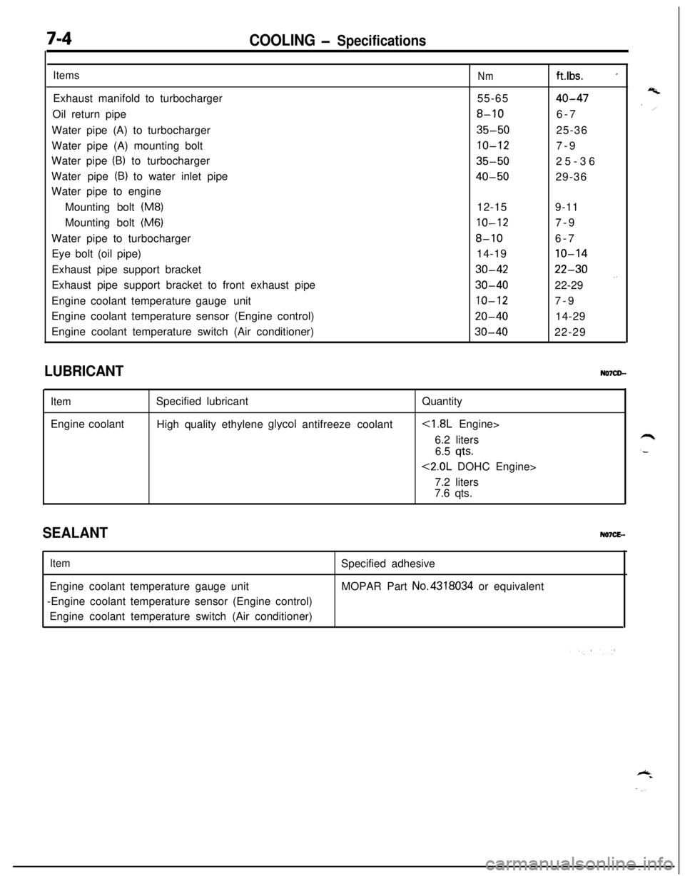
7-4COOLING - Specifications
ItemsExhaust manifold to turbocharger
Oil return pipe
Water pipe (A) to turbocharger
Water pipe (A) mounting bolt
Water pipe
(B) to turbocharger
Water pipe
(B) to water inlet pipe
Water pipe to engine
Mounting bolt
(M8)Mounting bolt
(M6)Water pipe to turbocharger
Eye bolt (oil pipe)
Exhaust pipe support bracket
Exhaust pipe support bracket to front exhaust pipe
Engine coolant temperature gaugeunit
Engine coolant temperature sensor (Engine control)
Engine coolant temperature switch (Air conditioner)
Nmft.lbs. _155-65
40-47
8-106-7
35-5025-36
10-127-9
35-5025-36
40-5029-36
12-159-11
10-127-9
8-106-7
14-19
10-14
30-4222-30
30-4022-29 .’
10-127-9
20-4014-29
30-4022-29
LUBRICANT
ItemEngine coolantSpecified lubricant
High quality ethylene
glycol antifreeze coolantQuantity
6.2 liters
6.5
qts.
<2.0L DOHC Engine>
7.2 liters
7.6 qts.
SEALANTNO7CE-.
ItemEngine coolant temperature gauge unit
-Engine coolant temperature sensor (Engine control)
Engine coolant temperature switch (Air conditioner)Specified adhesive
MOPAR Part No.4318034 or equivalent
Page 253 of 1216

COOLING - Troubleshootina7-5
TRO,UBLESHOOTlNG
Symptom
OverheatProbable causeInsufficient engine coolant
Too high an anti-freeze concentrationRemedy
Replenish
Correct anti-freeze
concentration
Loose or broken drive belt
Replace
Inoperative electric cooling fan
Faulty thermosensor
Replace
Faulty electrical motorReplace
Faulty radiator fan relayReplace
Damaged or blocked (insufficiently ventilated) radiator finsCorrect
Water leaks
Damaged radiator core joint
Replace
Corroded or cracked hosesReplace
(radiator hose, heater hose, etc.)
Loose bolt or leaking gasket in water outlet fitting
(thermostat)
Loose water pump mounting bolt or leaking gasket
Faulty cap valve or setting of spring
Loose intake manifold bolts or leaking from gasket
Cracked intake manifold
Faulty automatic transaxle oil cooler operation
Blocked or collapsed hose and pipe
Loose hose and pipe connection
Faulty thermostat operation
Faulty water pump operation
Water passage clogged with slime or rust deposit or
foreign substanceCorrect or replace
Correct or replace
Replace
Retorque bolts or replace
gasket
Replace
Replace
Correct
Replace
Replace
Clean
Jo rise in temperatureFaulty thermostatReplace
Page 255 of 1216
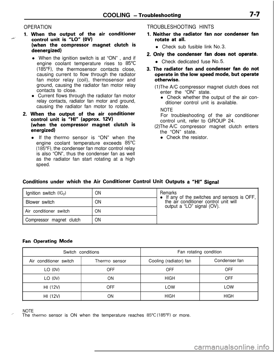
COOLING - Troubleshooting7A7
OPERATION
1. When the output of the air conditioner*--control unit is “LO” (OV)(when the
compressor magnet clutch isdeenergized)
l When the ignition switch is at “ON” , and if
engine coolant temperature rises to
85°C
(185”F), the thermosensor contacts close,
causing current to flow through the radiator
fan motor relay (coil), thermosensor and
ground, causing the radiator fan motor relay
contacts to close.
l Current flows through the radiator fan motor
relay contacts, radiator fan motor and ground,causing the radiator fan motor to rotate.
2. When the output of the air conditioner
control unit is “HI” (approx. 12V)(when the
compressor magnet clutch is
energized)l If the therm0 sensor is “ON” when the
engine coolant temperature exceeds
85°C
(185°F). the condenser fan motor control relay
is also “ON”, thus the condenser fan as well
as the radiator fan start rotating at a high
speed.
TROUBLESHOOTING HINTS
1. Neither the radiator fan nor condenser fanrotate at
all.l Check sub fusible link
No.3.
2. Only the condenser fan does not operate.l Check dedicated fuse
No.5.
3. The radiator fan and condenser fan do notoperate
in the low speed mode, but operateotherwise.
(1)The A/C compressor magnet clutch does not
enter the “ON” state.
l Check whether the output of the air con-
ditioner control unit is available.
NOTEFor troubleshooting of the air conditioner
control unit, refer to GROUP 24.
(2)The A/C compressor magnet clutch enters
the “ON” state.
l Check the resistor.Conditions
under which the Air Conditioner Control Unit Outputs a “HI” Signal
Ignition switch (IG2)
Blower switchAir conditioner switch
Compressor magnet clutch
ON
ON
ON
ON
Remarksl If any of the switches and sensors is OFF,
the air conditioner control unit will
output a “LO” signal (OV).
Fan Operating Mode
Switch conditions
Air conditioner switch
Therm0 sensor
LO
(OV)OFFLO
(OV)ONHI
(12V)OFFHI
(12V)ONFan rotating condition
Cooling (radiator) fanCondenser fan
OFFOFF
HIGHOFF
LOWLOW
HIGHHIGH
NOTE
_-The therm0 sensor is ON when the temperature reaches 85°C (185°F) or more.