drain bolt MITSUBISHI ECLIPSE 1991 Service Manual
[x] Cancel search | Manufacturer: MITSUBISHI, Model Year: 1991, Model line: ECLIPSE, Model: MITSUBISHI ECLIPSE 1991Pages: 1216, PDF Size: 67.42 MB
Page 45 of 1216
LUBRICATION AND MAINTENANCE - Maintenance ServiceO:lllO.AUTOMATIC TRANSAXLE (Inspect fluid
I~~+v~!1. Drive until the fluid temperature reaches the usual
temperature
[70-80°C (160- 18O”F)l.2. Place vehicle on level floor.
3.Move selector lever sequentially to every position to fill
torque converter and hydraulic
circuitwith fluid, then
place lever in“N” Neutral position. This operation is
necessary to be sure that fluid level check is accurate.
4.Before removing dipstick, wipe all dirt from area arounddipstick. Then take out the dipstick and check the
condition of the fluid.
The transaxle should be overhauled under the following
conditions.l If there is a “burning” odor.
l If the fluid color has become noticeably blacker.
l If there is a noticeably great amount of metal
particles in the fluid.
5.Check to see if fluid level is in “HOT” range on dipstick.If fluid level is low, add ATF until level reaches “HOT”
range.Low fluid level can cause a variety of conditions
because it allows pump to take in air along with fluid. Airtrapped in hydraulic circuit forms bubbles which make
fluid spongy. Therefore, pressures will be erratic.
Improper filling can also raise fluid level too high. Whentransaxle has too much fluid, gears churn up foam and
cause same conditions which occur with low fluid level,resulting in accelerated deterioration of ATF.
transmission fluid.
In either case, air bubbles can cause overheating, fluid
oxidation, which can interfere with normal valve, clutch,and servo operation. Foaming can also result in fluid
escaping from transaxle vent where it may be mistakenfor a leak.
6. Be sure to examine fluid on dipstick closely.lO.AUTOMATIC TRANSAXLE (Change fluid)
Drain the fluid and check whether there is any evidence of
contamination.
Replenish with new fluid after the cause of any contamina-tion has been corrected.
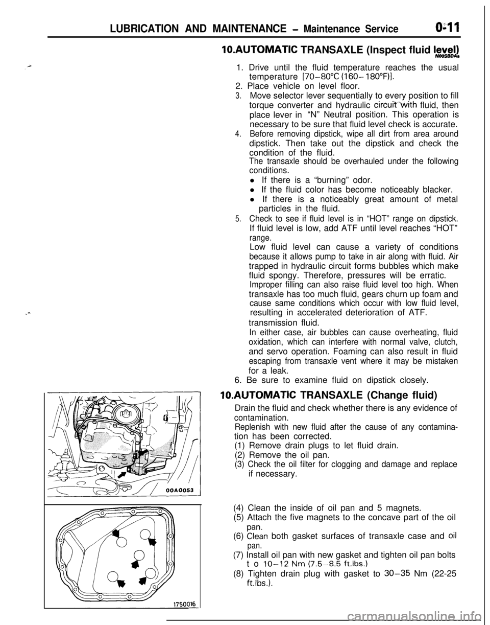
(1) Remove drain plugs to let fluid drain.
(2) Remove the oil pan.
(3) Check the oil filter for clogging and damage and replaceif necessary.
(4) Clean the inside of oil pan and 5 magnets.
(5) Attach the five magnets to the concave part of the oil
(6)
Elan both gasket surfaces of transaxle case and oil
pan.(7) Install oil pan with new gasket and tighten oil pan bolts
to
IO-12 Nm (7.5-8.5 ft.lbs.1(8) Tighten drain plug with gasket to
30-35 Nm (22-25
ftlbs.).
Page 105 of 1216
REAR AXLE - Specifications
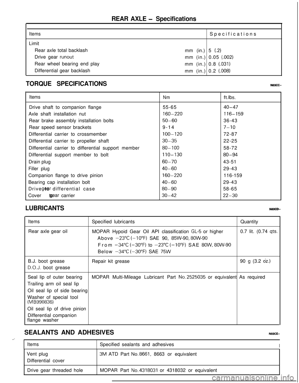
ItemsLimit
Rear axle total backlash
Drive gear
runoutRear wheel bearing end play
Differential gear backlashSpecifications
mm (in.) 5
(.2)mm (in.) 0.05
(.002)mm (in.) 0.8
(.031)mm (in.) 0.2
(.008)
TORQUE SPECIFICATIONS
ItemsNmft.lbs.
Drive shaft to companion flange55-65
40-47Axle shaft installation nut
160-220116-159Rear brake assembly installation bolts
50-6036-43
Rear speed sensor brackets9-14
7-10Differential carrier to crossmember
100-12072-87
Differential carrier to propeller shaft
30-3522-25
Differential carrier to differential support
member80- 10058-72
Differential support member to bolt
110-13080-94Drain plug
60-7043-51
Filler plug40-6029-43
Companion flange to drive pinion
160-220116-159
Bearing cap installation bolt
40-6029-43
Drive to differential case
gear80-9058-65
Cover to carrier
gear30-4222-30
LUBRICANTS
ItemsRear axle gear oilSpecified lubricantsQuantity
MOPAR Hypoid Gear Oil API classification
GL-5 or higher0.7 lit. (0.74 qts.Above
-23°C (-10°F) SAE 90, 85W-90, 8OW-90From
-34°C (-30°F) to -23°C (-10°F) SAE 8OW, 8OW-90Below
-34°C (-30°F) SAE 75WB.J. boot grease
D.O.J. boot greaseRepair kit grease90
g (3.2 dz.)Seal lip of outer bearingMOPAR Multi-Mileage Lubricant Part No.2525035 or equivalent As required
Trailing arm oil seal lip
Oil seal lip of side bearing
Washer of special tool
(M B990836)Oil seal lip of drive pinion
Differential companion
flange washer
SEALANTS AND ADHESIVES
..-
ItemsSpecified sealants and adhesivesIVent plug
Differential cover3M ATD Part
No.8661, 8663 or equivalent
Drive gear threaded holeMOPAR Part
No.4318031 or 4318032 or equivalent
Page 109 of 1216
REAR AXLE - Troubleshooting3-7
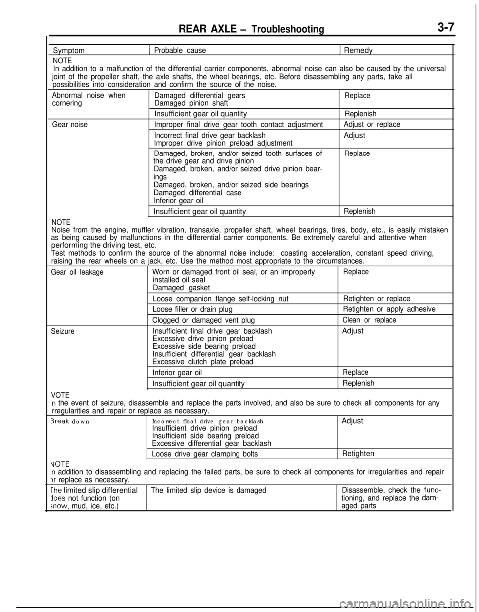
Symptom
NOTE
1 Probable cause1 Remedy
In addition to a malfunction of the differential carrier components, abnormal noise can also be caused by the universal
joint of the propeller shaft, the axle shafts, the wheel bearings, etc. Before disassembling any parts, take all
possibilities into consideration and confirm the source of the noise.
Abnormal noise when
Damaged differential gears
ReplacecorneringDamaged pinion shaftInsufficient gear oil quantity
Replenish
Gear noiseImproper final drive gear tooth contact adjustmentAdjust or replace
Incorrect final drive gear backlashAdjust
Improper drive pinion preload adjustment
Damaged, broken, and/or seized tooth surfaces of
Replacethe drive gear and drive pinion
Damaged, broken, and/or seized drive pinion bear-
ings
NOTE
Damaged, broken, and/or seized side bearings
Damaged differential case
Inferior gear oilInsufficient gear oil quantity
Replenish
Noise from the engine, muffler vibration, transaxle, propeller shaft, wheel bearings, tires, body, etc., is easily mistaken
as being caused by malfunctions in the differential carrier components. Be extremely careful and attentive whenperforming the driving test, etc.
Test methods to confirm the source of the abnormal noise include:coasting acceleration, constant speed driving,
raising the rear wheels on a jack, etc. Use the method most appropriate to the circumstances.
Gear oil leakageWorn or damaged front oil seal, or an improperlyReplace
installed oil seal
Damaged gasket
Seizure
VOTE
Loose companion flange self-locking nut
Loose filler or drain plug
Clogged or damaged vent plug
Insufficient final drive gear backlash
Excessive drive pinion preload
Excessive side bearing preload
Insufficient differential gear backlash
Excessive clutch plate preload
Inferior gear oilInsufficient gear oil quantityRetighten or replace
Retighten or apply adhesive
Clean or replaceAdjust
Replace
Replenish
n the event of seizure, disassemble and replace the parts involved, and also be sure to check all components for any
rregularities and repair or replace as necessary.
3reak downIncorrect final drive gear backlashAdjustInsufficient drive pinion preload
Insufficient side bearing preload
Excessive differential gear backlash
Loose drive gear clamping boltsRetighten
VOTEn addition to disassembling and replacing the failed parts, be sure to check all components for irregularities and repairIr
replace as necessary.
The limited slip differentialThe limited slip device is damagedDisassemble, check the func-
lees not function (ontioning, and replace the dam-
;now, mud, ice, etc.)aged parts
Page 121 of 1216
REAR AXLE - Differential Carrier
DIFFERENTIAL CARRIER
3-19
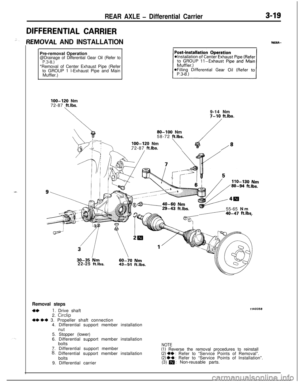
lEMOVAL AND INSTALLATIONN03lA--Pre-removal Operation
@Drainage of Differential Gear Oil (Refer toP.3-8.)*Removal of Center Exhaust Pipe (Refer
to GROUP 1 l-Exhaust Pipe and Main
Muffler.)
loo-120 Nm
72-87 ft.lbs.
\9-14 Nm7-10 ft.lbs.
80-100 Nm
58-72 ft.lbs.
loo-120 Nm
72-87 ftlbs.\/*
91hl A-55-65 Nm-/40-47 ftilis.22-25
ft.lbs.
Removal steps
4*I. Drive shaft
2. Circlip~~ ++ 3. Propeller shaft connection
4. Differential support member installation
nut
5. Stopper (lower)
6. Differential support member installation
llA0358
I Ibolts
7. Differential support member
8. Differential support member installation
bolts
9. Differential carrier
NOTE(I) Reverse the removal procedures to reinstall(2) +I) : Refer to “Service Points of Removal”.(2) W : Refer to “Service Points of Installation”.
(3) m : Non-reusable parts.
Page 200 of 1216
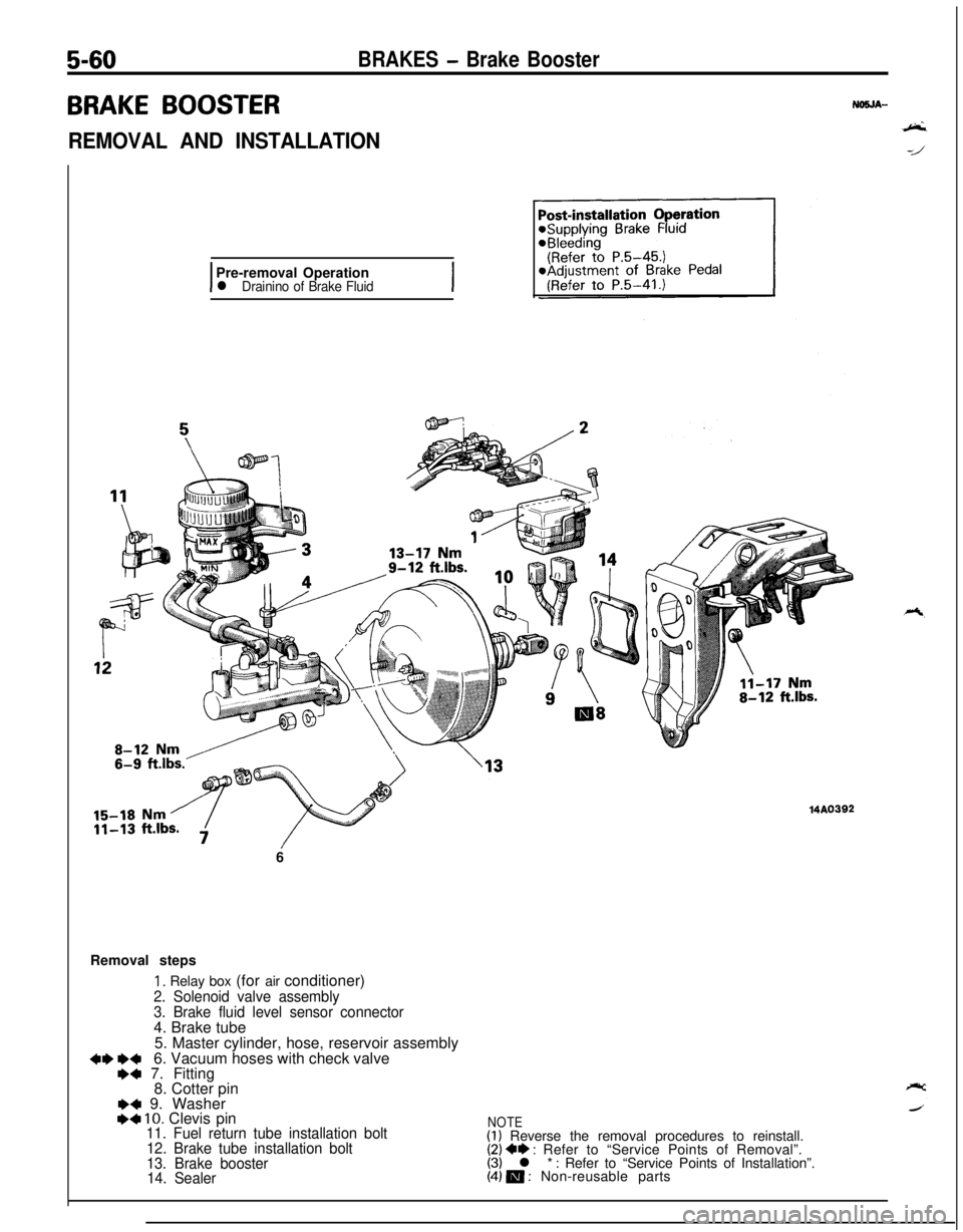
5-60BRAKES - Brake Booster
BRAKE BOOSTER
REMOVAL AND INSTALLATION
IPre-removal Operationl Drainino of Brake FluidI6
Removal steps
1. Relay box (for air conditioner)
2. Solenoid valve assembly
3. Brake fluid level sensor connector4. Brake tube
5. Master cylinder, hose, reservoir assembly
+I) e+6. Vacuum hoses with check valve+a 7. Fitting
8. Cotter pin
I)4 9. WasherI)4 10. Clevis pin11. Fuel return tube installation bolt
12. Brake tube installation bolt
13. Brake booster
14. Sealer
MA0392
NOTE(1) Reverse the removal procedures to reinstall.(2) ** : Refer to “Service Points of Removal”.(3) l * : Refer to “Service Points of Installation”.(4) m : Non-reusable parts
Page 279 of 1216
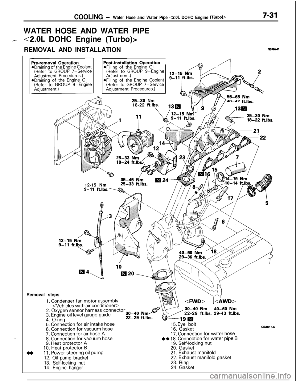
COOLING -Water Hose and Water Pipe <2.0L DOHC Engine (Turbo)>7-31WATER HOSE AND WATER PIPE
7--<2.0L DOHC Engine (Turbo)>
REMOVAL AND INSTALLATION
N071A-C
. .
ation OperationPost-installi@Filling of the Engine Oil(Refer to GROUP g-EngineaFilling of the
Engine Coolant(Refer to GROUP 7-ServiceAdjustment Procedures.)
Pre-removal OperationeDraining of the Engine Coolant(Refer to GROUP 7-ServiceAdjustment Procedures.)*Draining of the Engine Oil(Refer to GROUP g-Engine
25-30 Nm
18-22 ftlbs.4n-47 ft.lbs.
w35-45 N/m12-15 Nm25-33 ft.lbs.
9- 11ft.lbs.----Q&Removal steps
1. Condenser fan motor assembly
4*11. Power steering oil pump
12. Oil pump bracket
13. Self-locking nut
14. Engine hanger22-29
ft.lbs. 29-43 ft.lbs.
15. Eye bolt16. Gasket17. Connection for water hose
I)+ 18. Connection for water pipe B19. Self-locking nut20. Gasket21. Exhaust manifold22. Exhaust manifold gasket
23. Ring
24. Gasket
05m154
Page 302 of 1216
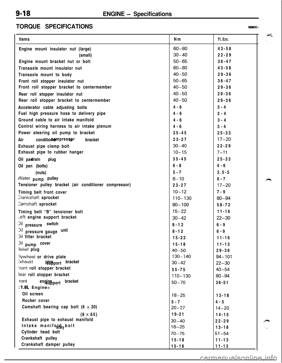
9-18ENGINE - Specifications
TORQUE SPECIFICATIONS
NO9CG-Items
Engine mount insulator nut (large)
(small)
Engine mount bracket nut or bolt
Transaxle mount insulator nut
Transaxle mount to body
Front roll stopper insulator nut
Front roll stopper bracket to centermember
Rear roll stopper insulator nut
Rear roll stopper bracket to centermember
Accelerator cable adjusting bolts
Fuel high pressure hose to delivery pipe
Ground cable to air intake manifold
Control wiring harness to air intake plenum
Power steering oil pump to bracket
Air conditioner to bracketcompressor
Exhaust pipe clamp bolt
Exhaust pipe to rubber hanger
Oil drain plug
panOil (bolts)
pan(nuts)VVater pulley
pump
Tensioner pulley bracket (air conditioner compressor)
Timing belt front coverCrankshaft sprocket
Camshaft sprocket
Timing belt “B” tensioner bolt
-eft engine support bracket3il switch
pressure3il unit
pressure gauge
Iii filter bracket
Iii cover
pumpqelief plug
‘lywheel or drive plate
ixhaust pipe bracket
support
‘rant roll stopper bracket
Iear roll stopper bracket‘rant engine bracket
support
:1.8L Engine>
Oil screen
Rocker cover
Camshaft bearing cap bolt (6 x 20)
(8 x 65)
Exhaust pipe to exhaust manifold
Intake manifold bolt
stay
Cylinder head bolt
Crankshaft pulley
Crankshaft damper pulleyNm
ftlbs.
60-8043-58
30-4022-29
50-6536-47
60-8043-58
40-5029-36
50-6536-47
40-5029-36
40-5029-36
40-5029-36
4-63-4
4-6
3-4
4-6
3-4
4-6
3-4
35-45
25-33
23-27
17-20
30-4022-29
10-157-l 135-45
25-33
6-84-6
5-73.5-5
8-106-7
23-27
17-20
10-127-9
110-13080-94
80-10058-72
15-2211-16
30-4222-308-126-9
8-126-9
15-2211-16
15-1811-13
40-5029-36
130-14094-101
30-4222-3055-75
40-54
110-13080-94
50-7036-51
18-2513-18
5-74-5
20-2714-2019-21
14-15
30-4022-29
18-2513-18
70-7551-5415-1811-13
15-1811-13
Page 318 of 1216
-
c/
(Refer to GROUP O-Maintenance
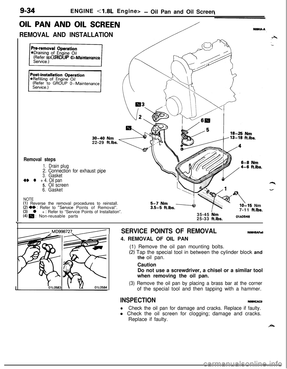
9-34ENGINE <1.8L Engine>- Oil Pan and Oil Screen
OIL PAN AND OIL SCREEN
REMOVAL AND INSTALLATION
30-40 Nm22-29 ftlbs.
Removal steps
1.Drain plug
2. Connection for exhaust pipe
3.Gasket
** l + 4. Oil pan5.Oil screen
6.Gasket
NOTE(1) Reverse the removal procedures to reinstall.(2) +e : Refer to “Service Points of Removal”.(3) l + : Refer to “Service Points of Installation”.(4) m : Non-reusable parts
lo-15 Nm
7-11 ftlbs.35-45 Nm25-33 ftlbs.OlAO546
,,Mq998727_/ 1SERVICE POINTS OF REMOVALNOSHBAFaO4. REMOVAL OF OIL PAN
(1) Remove the oil pan mounting bolts.
(2) Tap the special tool in between the cylinder block and
the oil pan.
Caution
Do not use a screwdriver, a chisel or a similar tool
when removing the oil pan.
(3) Remove the oil pan by placing a brass bar at the cornerof the special tool and then tapping with a hammer.
INSPECTIONNOHCACO
lCheck the oil pan for damage and cracks. Replace if faulty.l Check the oil screen for clogging; damage and cracks.
Replace if faulty.
Page 342 of 1216
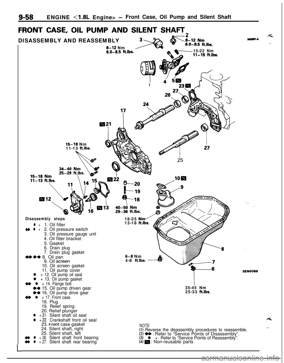
9-58ENGINE <1.8L Engine> -Front Case, Oil Pump and Silent Shaft
FRONT CASE, OIL PUMP AND SILENT SHAFTrl
L
I1
26:
25
15-18 Nm
11-13 ftlbs.DISASSEMBLY AND REASSEMBLY8-12 Nm
6.0-8.5 ft.lbs.15-22 Nm11-15 ft.lbs.
Disassembly steps
l +1. Oil filter~~ l +2. Oil pressure switch
3. Oil pressure gauge unit4. Oil filter bracket
5. Gasket
6. Drain plug
7. Drain plug gasket
+e*+ 8. Oil pan
9. Oil screen10. Oil screen gasket
11. Oil pump cover18-25
Nm/13-18 ftlbs.
8-8 Nm
4-8 ft.lbs.
l + 12. Oil pump oil seall + 13. Oil pump gasket
~~ l + 14. Flange boltI)+ 15. Oil pump driven geare+ 16. Oil pump drive gear
+e l + 17. Front case18. Plug
19. Relief spring20. Relief plunger
l + 21.Silent shaft oil seal
l + 22.Crankshaft front oil seal
35-45 Nm25-33 ftlbs.23.
Front case gasket
24. Silent shaft, right
25. Silent shaft, left
4* l + 26.Silent shaft front bearing~~ l + 27.Silent shaft rear bearing
i=G.NogRF-A.r
3EN0088
NOTE(1) Reverse the disassembly procedures to reassemble.(2) +e : Refer to “Service Points of Disassembly”.(3) l + : Refer to “Service Points of Reassembly”.(4) 0 : Non-reusable parts
Page 372 of 1216
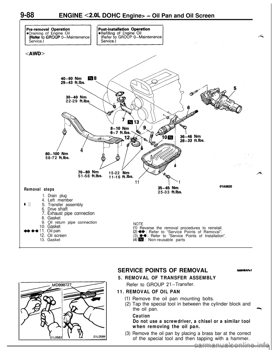
9-88ENGINE <2.0L DOHC Engine> - Oil Pan and Oil Screen
/
40-60 Nm
30-40 Nm22-29 ft.lbs..
/80-100 Nm458-72
ft.lbs.
70-80 Nm-51-58 ftlbs.15-22 vNm11-16 ft
11b1
Removal steps
1.Drain plug4.Left member
l *5. Transfer assembly6.Drive shaft
7. Exhaust pipe connection
8.Gasket9. Oil return pipe connection
10.Gasket***+ll. Oilpan
12.Oil screen13.Gasket
35-4; Nm25-33 ftlbs.
OlAO620
NOTE(I) Reverse the removal procedures to reinstall.(2) +I) : Refer to “Service Points of Removal”.
(3) H : Refer to “Service Points of Installation”.(4) m : Non-reusable parts
SERVICE POINTS OF REMOVAL
NOBHBAFal
5. REMOVAL OF TRANSFER ASSEMBLYRefer to GROUP 21-Transfer.
11. REMOVAL OF OIL PAN
(1) Remove the oil pan mounting bolts.
(2) Tap the special tool in between the cylinder block and
the oil pan.
Caution
Do not use a screwdriver, a chisel or a similar tool
when removing the oil pan.
(3) Remove the oil pan by placing a brass bar at the correctof the special tool and then tapping with a hammer.