ECU MITSUBISHI ECLIPSE 1993 Workshop Manual
[x] Cancel search | Manufacturer: MITSUBISHI, Model Year: 1993, Model line: ECLIPSE, Model: MITSUBISHI ECLIPSE 1993Pages: 57, PDF Size: 4.18 MB
Page 10 of 57
5-52
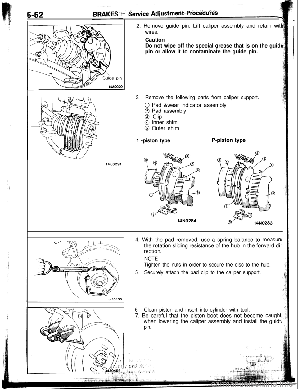
14LO2912. Remove guide pin. Lift caliper assembly and retain wit
wires.Caution
Do not wipe off the special grease that is on the guid
pin or allow it to contaminate the guide pin.
3.Remove the following parts from caliper support.
0 Pad &wear indicator assembly
0 Pad assembly
@ Clip
@I Inner shim
@ Outer shim
1 -piston type14N0284P-piston type
\14AO4004. With the pad removed, use a spring balance to
measurethe rotation sliding resistance of the hub in the forward di
rection.
NOTE
Tighten the nuts in order to secure the disc to the hub.
5.Securely attach the pad clip to the caliper support.
6.Clean piston and insert into cylinder with tool.7. Be careful that the piston boot does not become
caughlwhen lowering the caliper assembly and install the guidt
pin.
Page 12 of 57
14A0391
RUN-OUT CHECK
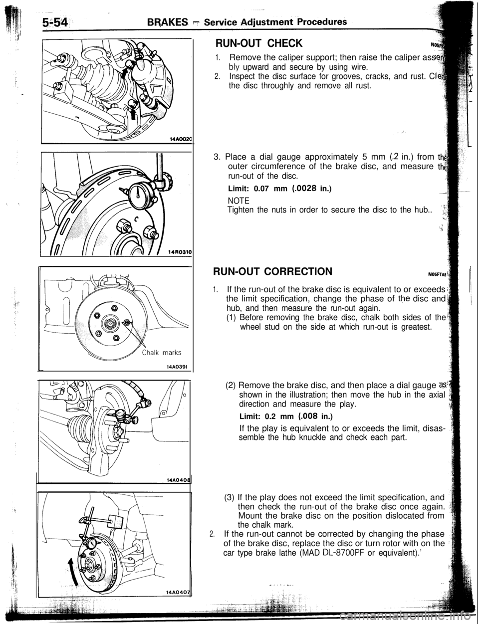
1.Remove the caliper support; then raise the caliper ass
bly upward and secure by using wire.
2.Inspect the disc surface for grooves, cracks, and rust. Cl
the disc throughly and remove all rust.3. Place a dial gauge approximately 5 mm
(.2 in.) from thiouter circumference of the brake disc, and measure
tt$
run-out of the disc._iLimit: 0.07 mm
(.0028 in.)-2
NOTE
Tighten the nuts in order to secure the disc to the hub..‘l;i,!
..,;RUN-OUT CORRECTION
NOSFTAB
1.If the run-out of the brake disc is equivalent to or exceeds
the limit specification, change the phase of
the disc and
hub, and then measure the run-out again.
(1) Before removing the brake disc, chalk both sides of the
wheel stud on the side at which run-out is greatest.(2) Remove the brake disc, and then place a dial gauge
2s
shown in the illustration; then move the hub in the axial
direction and measure the play.Limit: 0.2 mm
(.008 in.)
If the play is equivalent to or exceeds the limit, disas-
semble the hub knuckle and check each part.
2.(3) If the play does not exceed the limit specification, and
then check the run-out of the brake disc once again.
Mount the brake disc on the position dislocated from
the chalk mark.If the run-out cannot be corrected by changing the phase
of the brake disc, replace the disc or turn rotor with on the
car type brake lathe (MAD DL-8700PF or equivalent).’
.,“, . . . -..
Page 14 of 57
BRAKES -Brake BoosterVacuum hose
14AO39414u0050Semidrvina sealant
141626Vacuum hose
IChevk valve
mm (in.)
14AO395
SERVICE PO@JTS OF REMOVALNocm6.
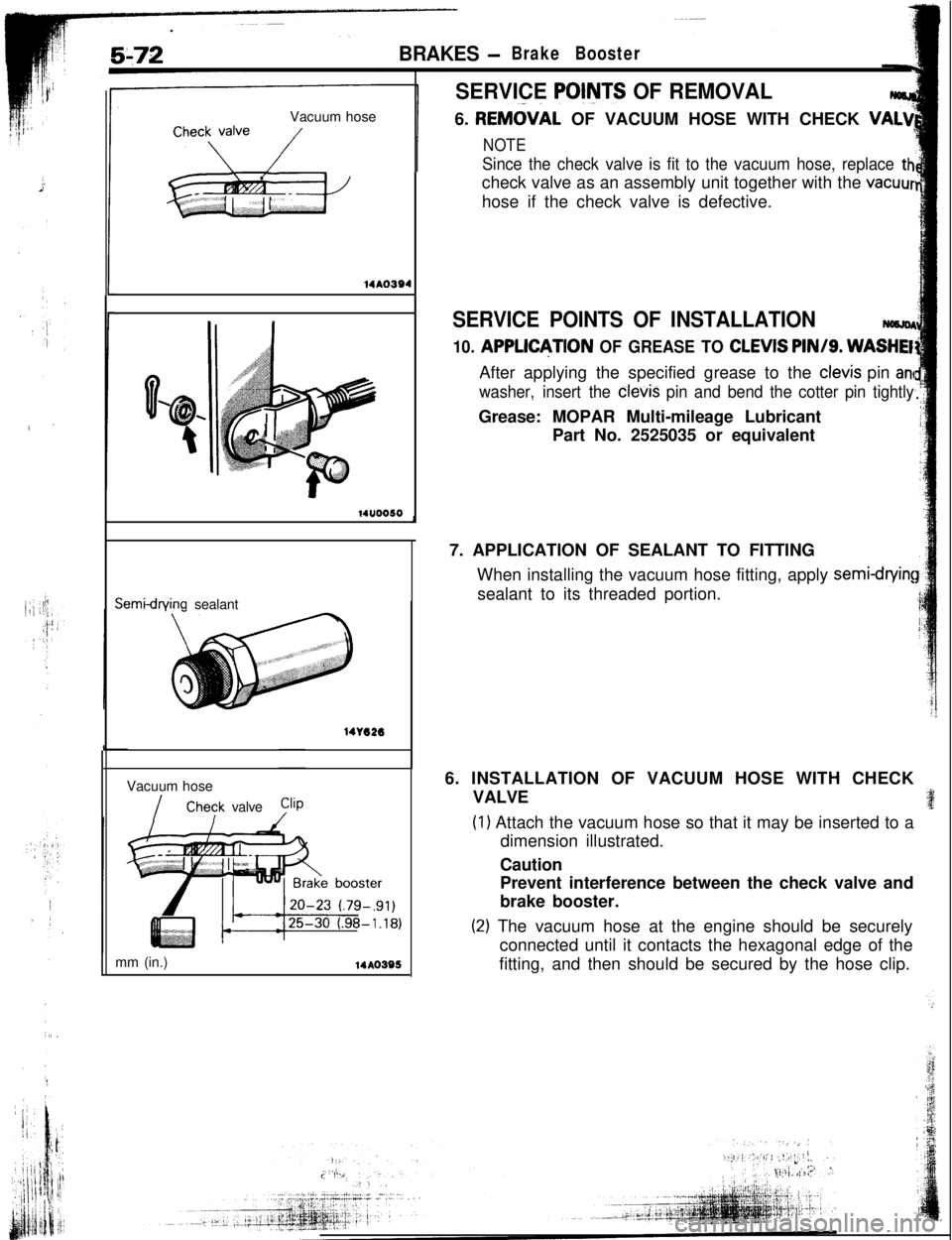
REM&AL OF VACUUM HOSE WITH CHECK VA+
NOTE
Since the check valve is fit to the vacuum hose, replace thcheck valve as an assembly unit together with the
vacuurhose if the check valve is defective.
SERVICE POINTS OF INSTALLATION
10. APPLDJTION OF GREASE TO CLEVIS PIN/g. WASHEIAfter applying the specified grease to the
clevis pin an
washer, insert the
cievis pin and bend the cotter pin tightlyGrease: MOPAR Multi-mileage Lubricant
Part No. 2525035 or equivalent
7. APPLICATION OF SEALANT TO FITTING
When installing the vacuum hose fitting, apply
semi-cfryin!sealant to its threaded portion.
6. INSTALLATION OF VACUUM HOSE WITH CHECK
VALVE
(1) Attach the vacuum hose so that it may be inserted to a
dimension illustrated.
Caution
Prevent interference between the check valve and
brake booster.
(2) The vacuum hose at the engine should be securely
connected until it contacts the hexagonal edge of the
fitting, and then should be secured by the hose clip.
Page 19 of 57
-
3AF
:dSERVICE POINTS OF INSTALLATION
NOBLDAG2.
INSTILLATION OF FRONT BRAKE ASSEMBLY
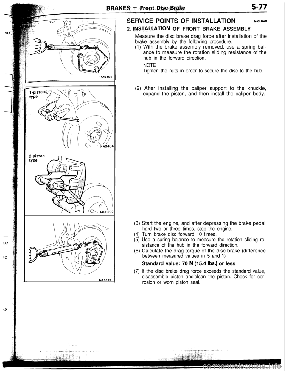
14AO399Measure the disc brake drag force after installation of the
brake assembly by the following procedure.(1) With the brake assembly removed, use a spring bal-
ance to measure the rotation sliding resistance of the
hub in the forward direction.
NOTE
Tighten the nuts in order to secure the disc to the hub.(2) After installing the caliper support to the knuckle,
expand the piston, and then install the caliper body.
(3) Start the engine, and after depressing the brake pedal
hard two or three times, stop the engine.
(4) Turn brake disc forward 10 times.
(5) Use a spring balance to measure the rotation sliding re-
sistance of the hub in the forward direction.(6) Calculate the drag torque of the disc brake (difference
between measured values in 5 and 1).Standard value: 70
N (15.4 Ibs.) or less
(7) If the disc brake drag force exceeds the standard value,
disassemble piston and’clean the piston. Check for cor-
rosion or worn piston seal.
Page 29 of 57
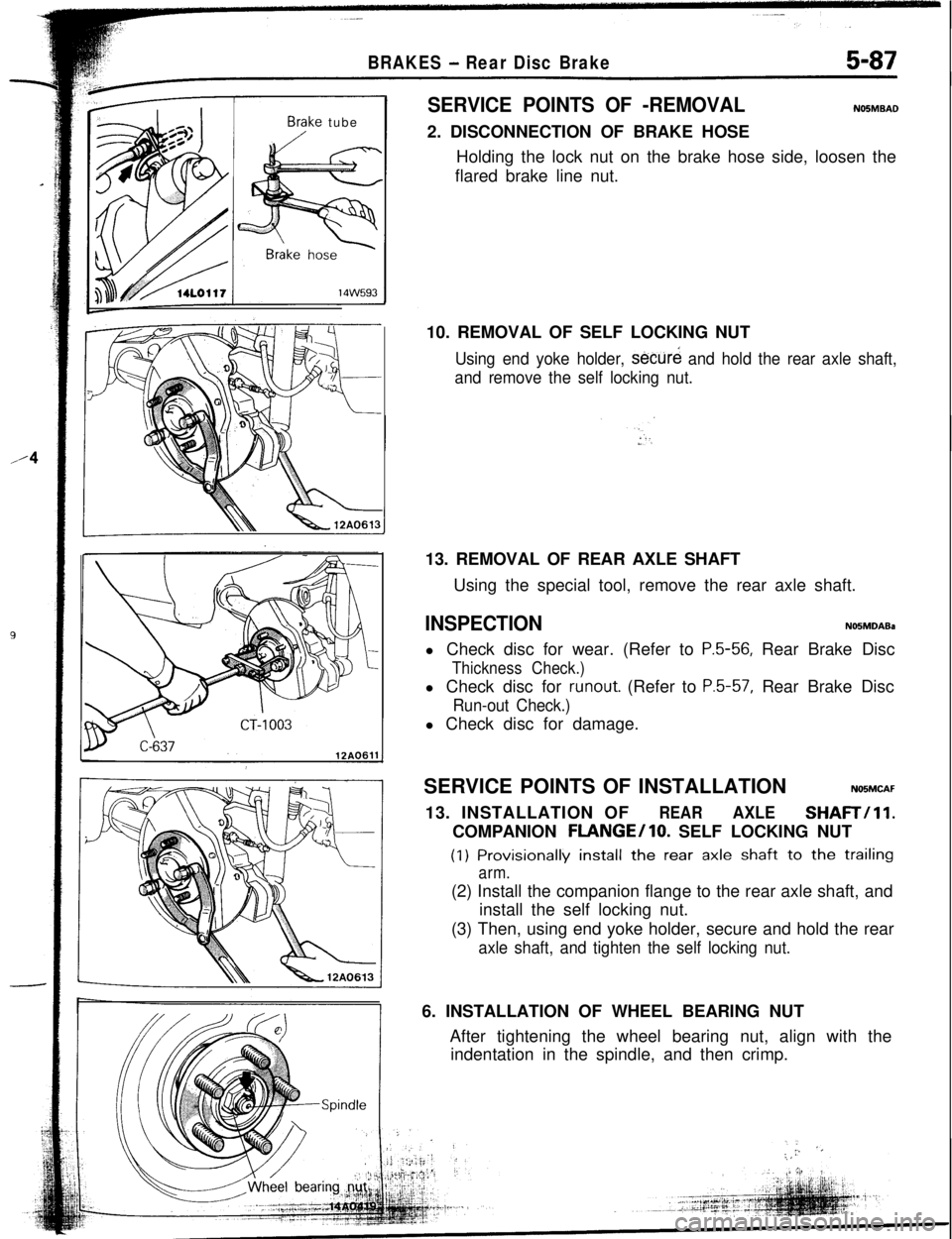
Brake tubeSERVICE POINTS OF -REMOVALNO5MBAD2. DISCONNECTION OF BRAKE HOSE
Holding the lock nut on the brake hose side, loosen the
flared brake line nut.
BRAKES - Rear Disc Brake5-8710. REMOVAL OF SELF LOCKING NUT
Using end yoke holder, secure and hold the rear axle shaft,
and remove the self locking nut.13. REMOVAL OF REAR AXLE SHAFT
Using the special tool, remove the rear axle shaft.
INSPECTIONNOSMDABal Check disc for wear. (Refer to
P.5-56, Rear Brake Disc
Thickness Check.)l Check disc for
runout. (Refer to P.5-57, Rear Brake Disc
Run-out Check.)l Check disc for damage.
SERVICE POINTS OF INSTALLATION
NOBMCAF13. INSTALLATION OF
REARAXLESHAFTill.COMPANION
FLANGE/lo. SELF LOCKING NUT(1)
Provisionally install the rear axle shaft to the trailing
arm.(2) Install the companion flange to the rear axle shaft, and
install the self locking nut.
(3) Then, using end yoke holder, secure and hold the rear
axle shaft, and tighten the self locking nut.6. INSTALLATION OF WHEEL BEARING NUT
After tightening the wheel bearing nut, align with the
indentation in the spindle, and then crimp.
:. ‘.:,,
Page 55 of 57
I
23-74BODY - Aero Parts
\18AQ245
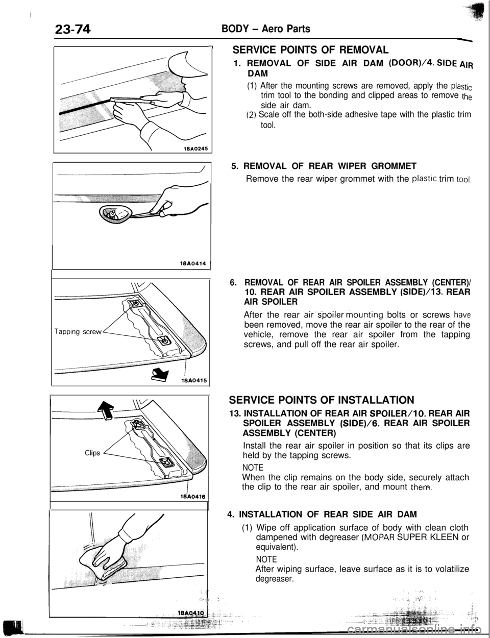
-ISERVICE POINTS OF REMOVAL1. REMOVAL OF SIDE AIR DAM
(DOOR)/4. SIDE AIRDAM
(1) After the mounting screws are removed, apply the plastic
trim tool to the bonding and clipped areas to remove the
side air dam.
(2) Scale off the both-side adhesive tape with the plastic trim
tool.
16AQ414J5. REMOVAL OF REAR WIPER GROMMET
Remove the rear wiper grommet with the
plastlc trim tool.
6.REMOVAL OF REAR AIR SPOILER ASSEMBLY (CENTER)/10. REAR AIR SPOILER ASSEMBLY (SIDE)/13. REAR
AIR SPOILERAfter the rear air’s’poiler mounting bolts or screws
hav2been removed, move the rear air spoiler to the rear of the
vehicle, remove the rear air spoiler from the tapping
screws, and pull off the rear air spoiler.
SERVICE POINTS OF INSTALLATION
13. INSTALLATION OF REAR AIR
SPOILER/lo. REAR AIR
SPOILER ASSEMBLY (SIDE)/G. REAR AIR SPOILER
ASSEMBLY (CENTER)
Install the rear air spoiler in position so that its clips are
held by the tapping screws.
NOTEWhen the clip remains on the body side, securely attach
the clip to the rear air spoiler, and mount
them.4. INSTALLATION OF REAR SIDE AIR DAM
(1) Wipe off application surface of body with clean cloth
dampened with degreaser
(MOPAR SUPER KLEEN or
equivalent).
NOTEAfter wiping surface, leave surface as it is to volatilize
degreaser.