torque MITSUBISHI ECLIPSE 1993 Workshop Manual
[x] Cancel search | Manufacturer: MITSUBISHI, Model Year: 1993, Model line: ECLIPSE, Model: MITSUBISHI ECLIPSE 1993Pages: 57, PDF Size: 4.18 MB
Page 3 of 57
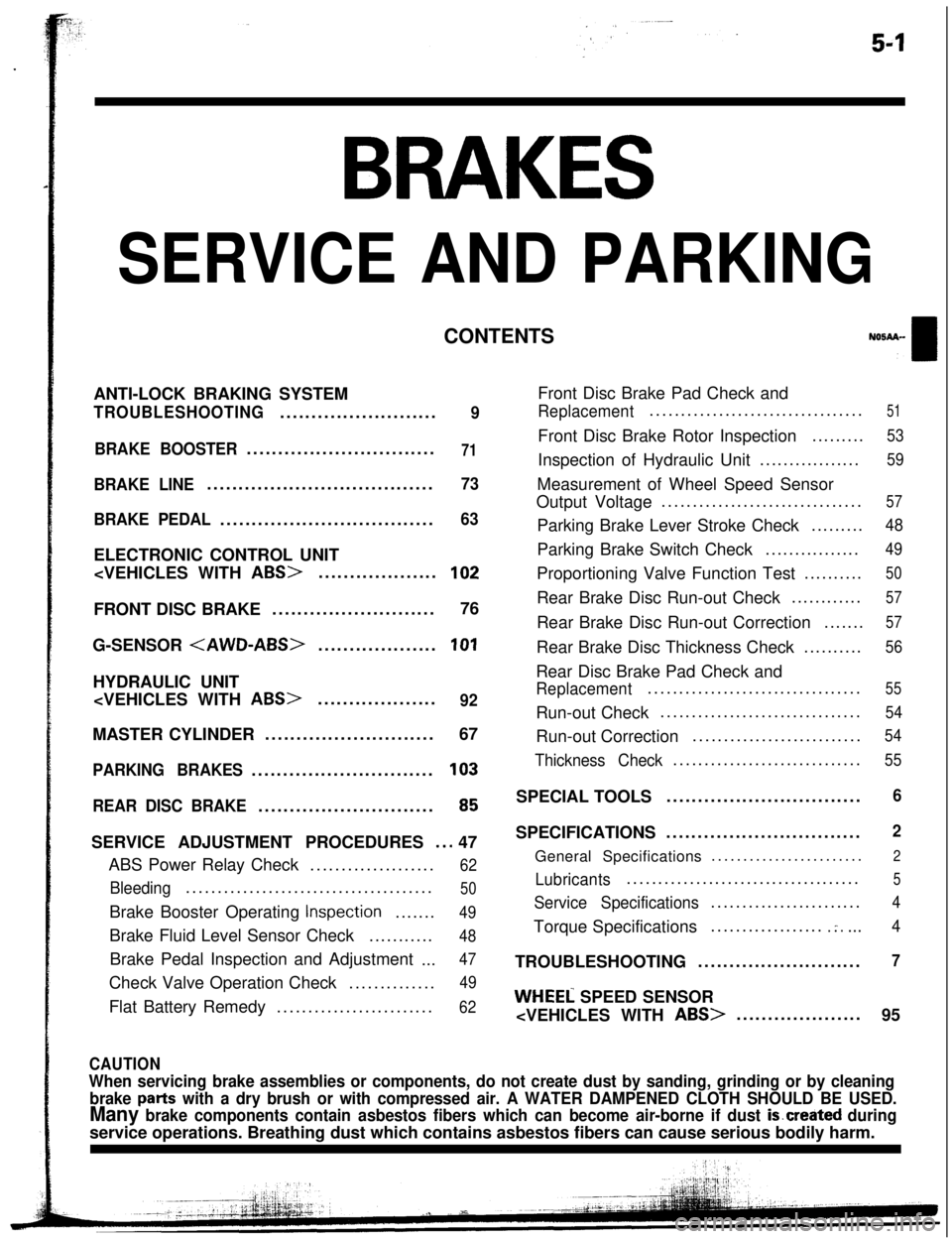
BRAKES
SERVICE AND PARKINGCONTENTS
ANTI-LOCK BRAKING SYSTEM
TROUBLESHOOTING.........................9
BRAKE BOOSTER..............................
71
BRAKE LINE....................................73
BRAKE PEDAL..................................
63ELECTRONIC CONTROL UNIT
G-SENSOR
PARKING BRAKES.............................103
REAR DISC BRAKE............................
65SERVICE ADJUSTMENT PROCEDURES
..a 47
ABS Power Relay Check....................
62
Bleeding.......................................50Brake Booster Operating
Inspection.......49Brake Fluid Level Sensor Check...........
48Brake Pedal Inspection and Adjustment
...
47Check Valve Operation Check..............
49Flat Battery Remedy.........................
62Front Disc Brake Pad Check and
Replacement..................................51Front Disc Brake Rotor Inspection.........
53Inspection of Hydraulic Unit.................
59Measurement of Wheel Speed Sensor
Output Voltage................................
57Parking Brake Lever Stroke Check.........
48Parking Brake Switch Check................
49Proportioning Valve Function Test..........
50Rear Brake Disc Run-out Check............
57Rear Brake Disc Run-out Correction.......
57Rear Brake Disc Thickness Check..........
56Rear Disc Brake Pad Check and
Replacement..................................55Run-out Check................................
54Run-out Correction...........................
54
Thickness Check..............................55SPECIAL TOOLS...............................
6SPECIFICATIONS...............................
2General Specifications........................
2
Lubricants.....................................5
Service Specifications........................4Torque Specifications..................
.:....4TROUBLESHOOTING..........................
7
WHEEL SPEED SENSOR
95
CAUTION
When servicing brake assemblies or components, do not create dust by sanding, grinding or by cleaning
brake
parts with a dry brush or with compressed air. A WATER DAMPENED CLOTH SHOULD BE USED.
Many brake components contain asbestos fibers which can become air-borne if dust is.created duringservice operations. Breathing dust which contains asbestos fibers can cause serious bodily harm.
Page 6 of 57
-
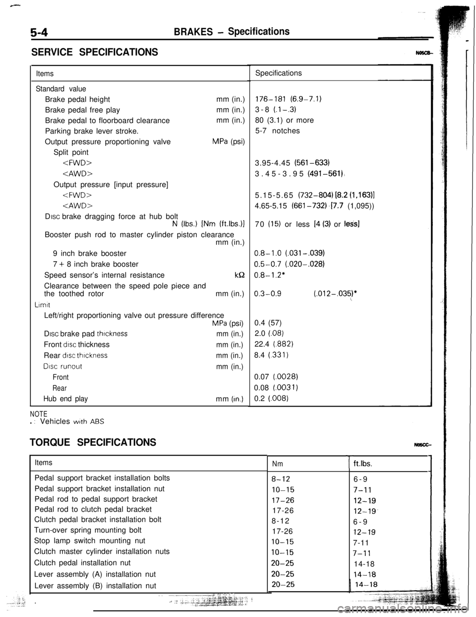
5-4BRAKES- Specifications
SERVICE SPECIFICATIONS
Items
Standard valueBrake pedal heightmm (in.)
Brake pedal free playmm (in.)
Brake pedal to floorboard clearancemm (in.)
Parking brake lever stroke.
Output pressure proportioning valve
MPa (psi)
Split point
N (Ibs.) [Nm (ft.lbs.)lBooster push rod to master cylinder piston clearance
mm (in.)
9 inch brake booster
7 + 8 inch brake booster
Speed sensor’s internal resistancek&
Clearance between the speed pole piece and
the toothed rotormm (in.)
LrmttLeft/right proportioning valve out pressure difference
MPa (psi)
DISC brake pad
thrcknessmm (in.)Front
drsc thicknessmm (in.)Rear
dtsc thrcknessmm (in.)
DISC runout
mm (in.)
Front
Rear
Hub end playmm (In.)
NOTEl : Vehicleswith ABS
TORQUE SPECIFICATIONSSpecifications176-181 (6.9-7.1)
3-8
(.l-.3)80 (3.1) or more
5-7 notches
3.95-4.45 (561-633)
3.45-3.95 (491-561).
5.15-5.65 (732-804) i8.2
(1,163)14.65-5.15 (661-732j.17.7 (1,095))
70
(15) or less I4 (3) or less]
0.8-1.0 (.031-,039)
0.5-0.7 (.020-.028)
0.8-1.2"
0.3-0.9 (.012-,035)"60.4 (57)
2.0
(.08)22.4
(.882)8.4
(.331)0.07
(.0028)0.08 l.0031)
0.2
(.008)
ItemsPedal support bracket installation bolts
Pedal support bracket installation nut
Pedal rod to pedal support bracket
Pedal rod to clutch pedal bracket
Clutch pedal bracket installation bolt
Turn-over spring mounting bolt
Stop lamp switch mounting nut
Clutch master cylinder installation nuts
Clutch pedal installation nut
Lever assembly (A) installation nut
Lever assembly (B) installation nut
I:: ::I .:‘i j ,:~~ -__j.-, .‘- ‘+‘+gg&p.~j:;.;1--?.+.k
Nm
8-12
IO-15
17-2617-26
8-12
17-26
10-15
10-15
20-25
20-25
20-25
Tft.lbs.
6-9
7-11
12-19
12-19.6-9
12-197-11
7-1114-18
14-18
Page 11 of 57
guiisur
dd
lght
clidc
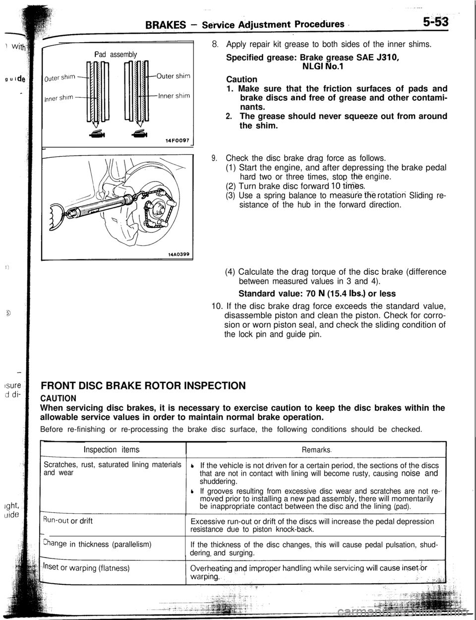
Pad assembly
luter shim
nner shim
43l a14FOO97
14A0399
Apply repair kit grease to both sides of the inner shims.Specified grease: Brake grease SAE 5310,
NLGI No.1Caution
1. Make sure that the friction surfaces of pads and
brake discs and free of grease and other contami-
nants.
2.The grease should never squeeze out from around
the shim.
9.Check the disc brake drag force as follows.(1) Start the engine, and after depressing the brake pedal
hard two or three times, stop the(2) Turn brake disc forward
10 tie&.
engine.
(3) Use a spring balance to meastiie fh-e rotation Sliding re-
sistance of the hub in the forward direction.(4) Calculate the drag torque of the disc brake (difference
between measured values in 3 and 4).Standard value: 70
N (15.4 Ibs.) or less
10. If the disc brake drag force exceeds
tlie standard value,
disassemble piston and clean the piston. Check for corro-
sion or worn piston seal, and check the sliding condition of
the lock pin and guide pin.FRONT DISC BRAKE ROTOR INSPECTION
CAUTIONWhen servicing disc brakes, it is necessary to exercise caution to keep the disc brakes within the
allowable service values in order to maintain normal brake operation.
Before re-finishing or re-processing the brake disc surface, the following conditions should be checked.
Inspection itemsRemarks
Scratches, rust, saturated lining materials
and wearlIf the vehicle is not driven for a certain period, the sections of the discsthat are not in contact with lining will become rusty, causing noise and
shuddering.
lIf grooves resulting from excessive disc wear and scratches are not re-moved prior to installing a new pad assembly, there will momentarily
beinappropriatecontact between the disc and thelining(pad).
Run-out or drift
Ehange in thickness (parallelism)Excessive run-out or drift of the discs will increase the pedal depression
resistance due to piston knock-back.
If the thickness of the disc changes, this will cause pedal pulsation, shud-
deringand surging.
Page 19 of 57
-
3AF
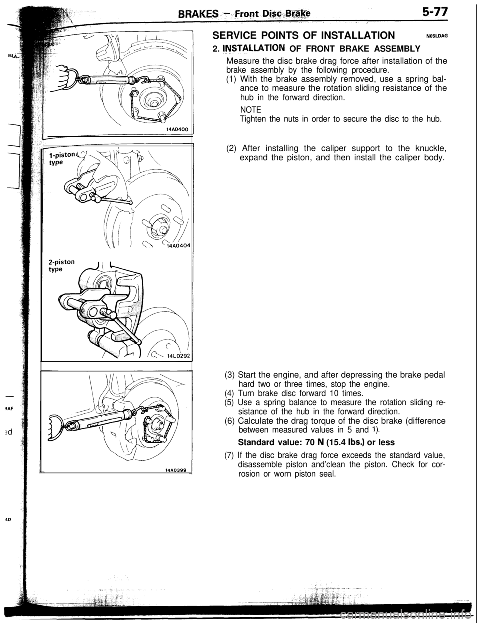
:dSERVICE POINTS OF INSTALLATION
NOBLDAG2.
INSTILLATION OF FRONT BRAKE ASSEMBLY
14AO399Measure the disc brake drag force after installation of the
brake assembly by the following procedure.(1) With the brake assembly removed, use a spring bal-
ance to measure the rotation sliding resistance of the
hub in the forward direction.
NOTE
Tighten the nuts in order to secure the disc to the hub.(2) After installing the caliper support to the knuckle,
expand the piston, and then install the caliper body.
(3) Start the engine, and after depressing the brake pedal
hard two or three times, stop the engine.
(4) Turn brake disc forward 10 times.
(5) Use a spring balance to measure the rotation sliding re-
sistance of the hub in the forward direction.(6) Calculate the drag torque of the disc brake (difference
between measured values in 5 and 1).Standard value: 70
N (15.4 Ibs.) or less
(7) If the disc brake drag force exceeds the standard value,
disassemble piston and’clean the piston. Check for cor-
rosion or worn piston seal.
Page 33 of 57
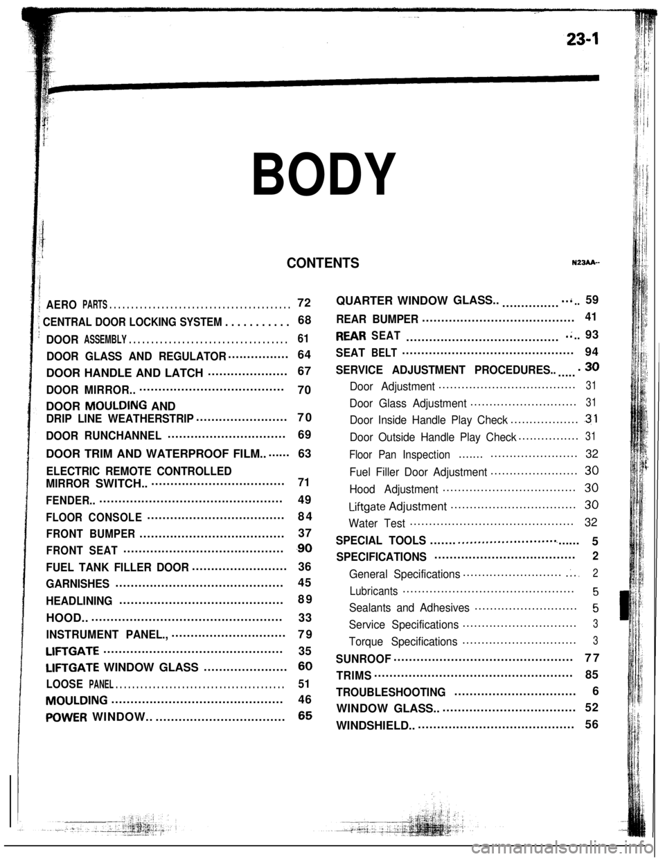
BODY
CONTENTS
,I
i
1AEROPARTS . . . . . . . . . . . . . . . . . . . . . . . . . . . . . . . . . . . . . . . . . .72
; CENTRAL DOOR LOCKING SYSTEM . . . . . . . . . . .68
’DOORASSEMBLY . . . . . . . . . . . . . . . . . . . . . . . . . . . . . . . . . . . .61
DOOR GLASS AND REGULATOR................
64
DOOR HANDLE AND LATCH.....................67QUARTER WINDOWGLASS..
...............
..i..59
REAR BUMPER........................................41
REARSEAT.........................................;..93
SEATBELT.............................................
94
SERVICE ADJUSTMENT PROCEDURES........30
Door Adjustment....................................31
Door Glass Adjustment............................31
Door Inside Handle Play Check...................31
Door Outside Handle Play Check................31
Floor PanInspection..............................
32
Fuel Filler Door Adjustment.......................30
Hood Adjustment...................................30
Liftgate Adjustment.................................30
Water Test...........................................
32
SPECIAL TOOLS....................*..........c......
5
SPECIFICATIONS.....................................2
General Specifications...........................;..2
Lubricants.............................................5
Sealants and Adhesives...........................5
Service Specifications..............................3
Torque Specifications..............................3
SUNROOF...............................................
77
TRIMS....................................................
85
TROUBLESHOOTING................................6
WINDOWGLASS.....................................52
WINDSHIELD...........................................56
DOORMIRROR........................................
70
DOOR
MOULDING AND
DRIP LINE WEATHERSTRIP........................
70
DOORRUNCHANNEL...............................
69
DOOR TRIM AND WATERPROOF FILM........
63
ELECTRIC REMOTE CONTROLLED
MIRRORSWITCH.....................................
71
FENDER..................................................
49
FLOORCONSOLE....................................
84
FRONTBUMPER......................................37
FRONTSEAT...........................................90
FUEL TANK FILLER DOOR.........................
36
GARNISHES............................................45
HEADLINING...........................................89
HOOD....................................................
33
INSTRUMENTPANEL.,..............................
79
Lll=l’GATE...............................................
35
LIFTGATE WINDOW GLASS......................60
LOOSEPANEL . . . . . . . . . . . . . . . . . . . . . . . . . . . . . . . . . . . . . . . . .51
MOULDING.............................................
46
POWERWINDOW....................................65
N23AA--
Page 50 of 57
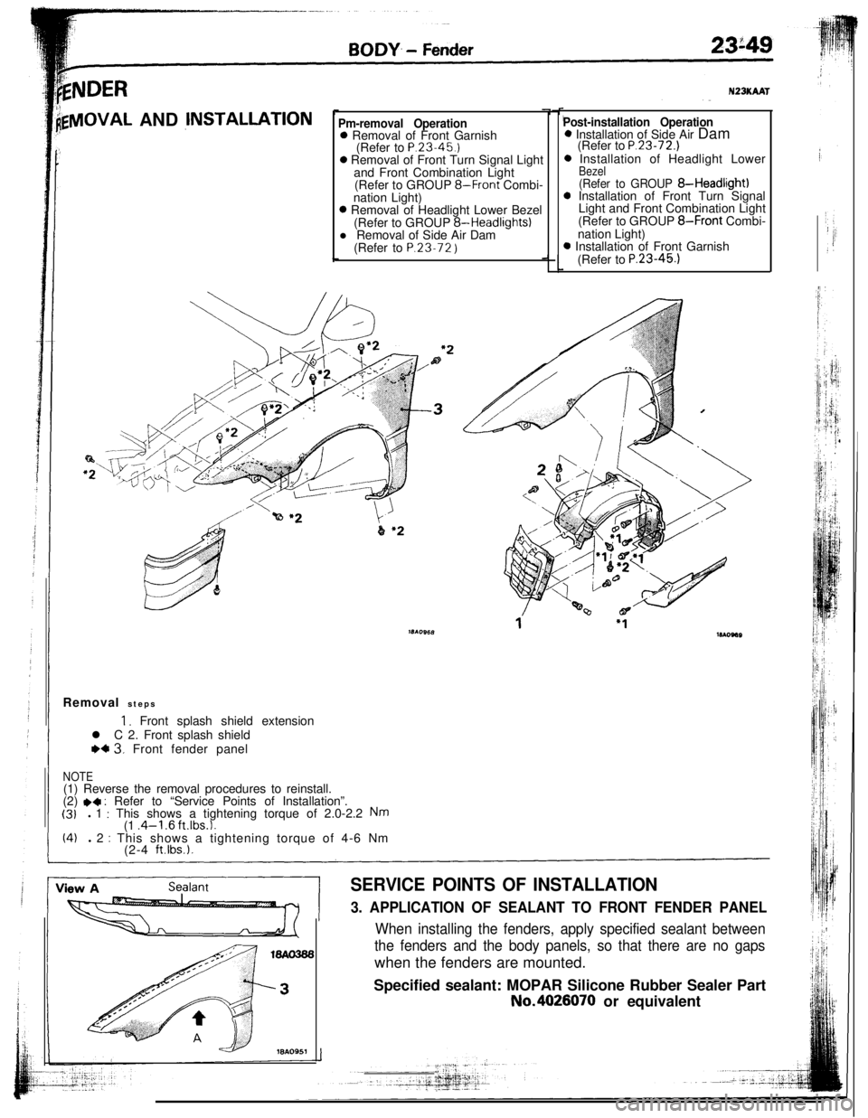
kNDER
lgVlOVAL AND jNSTALLATIONPm-removal Operation0 Removal of Front Garnish
(Refer to P.23.45.)0 Removal of Front Turn Signal Light
and Front Combination Light
(Refer to GROUP
8-Front Combi-
nation Light)0 Removal of Headlight Lower Bezel
(Refer to GROUP 8-Headlights)
l Removal of Side Air Dam
(Refer to P.23.72
)
N23KAAT
Post-installation Operation0 Installation of Side Air Dam
(Refer to
P.23-72.)0 Installation of Headlight Lower
Bezel(Refer to GROUP 8-Headlight)0 Installation of Front Turn Signal
Light and Front Combination Light
(Refer to GROUP
8-Front Combi-
nation Light)0 Installation of Front Garnish
(Refer to
P.23-45.1Removal steps
1, Front splash shield extension
l C 2. Front splash shield
WC 3. Front fender panel
NOTE(1) Reverse the removal procedures to reinstall.
(2)
.4 : Refer to “Service Points of Installation”.(31l 1 : This shows a tightening torque of 2.0-2.2 Nm(1 .4-l .6 ft.lbs.1.(4)l 2 : This shows a tightening torque of 4-6 Nm
(2-4 ft.lbs.).
SERVICE POINTS OF INSTALLATION
3. APPLICATION OF SEALANT TO FRONT FENDER PANEL
When installing the fenders, apply specified sealant between
the fenders and the body panels, so that there are no gapswhen the fenders are mounted.
Specified sealant: MOPAR Silicone Rubber Sealer PartNo.4026070 or equivalent