System control MITSUBISHI ECLIPSE CROSS 2019 Owner's Manual (in English)
[x] Cancel search | Manufacturer: MITSUBISHI, Model Year: 2019, Model line: ECLIPSE CROSS, Model: MITSUBISHI ECLIPSE CROSS 2019Pages: 423, PDF Size: 75.41 MB
Page 206 of 423
Tire pressure monitoring system (TPMS)
Features and controls 5-123
5
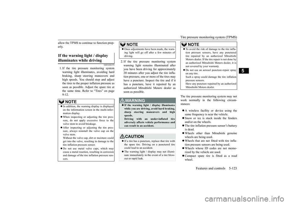
allow the TPMS to continue to function prop- erly.
N00532801579
1. If the tire pressure monitoring system warning light illuminates, avoiding hard braking, sharp steering maneuvers andhigh speeds. You should stop and adjustthe tires to the proper inflation pressure as soon as possible. Adjust the spare tire at the same time. Refer to “Tires” on page9-12.
2. If the tire pressure monitoring system warning light remains illuminated after you have been driving for approximately20 minutes after you adjust the tire infla- tion pressure, one or more of the tires may have a puncture. Inspect the tire and if ithas a puncture, have it repaired by anauthorized Mitsubishi Motors dealer as soon as possible.
The tire pressure monitoring system may not work normally in the following circum-stances: A wireless facility or device using the same frequency is near the vehicle. Snow or ice is stuck inside the fenders and/or on the wheels. The tire inflation pressure sensor’s battery is dead. Wheels other than Mitsubishi genuine wheels are being used. Wheels that are not fitted with tire infla- tion pressure sensors are being used. Wheels whose ID co
des are not memo-
rized by the vehicle are used. Compact spare tire is fitted as a road wheel.
If the warning light / display illuminates while driving
NOTE
In addition, the warning display is displayed on the information screen in the multi-infor- mation display. When inspecting or adjusting the tire pres- sure, do not apply excessive force to thevalve stem to avoid breakage. After inspecting or adjusting the tire pres- sure, always reinstall the valve cap on the valve stem. Without the valve cap, dirt or moisture could get into the valve, resulting in damage to the tire inflation pressure sensor. Do not use metal valve caps, which may cause a metal reaction, resulting in corrosionand damage of the tire inflation pressure sen- sors.
Once adjustments have been made, the warn- ing light will go off after a few minutes of driving.WA R N I N G If the warning light / display illuminates while you are driving, avoid hard braking,sharp steering maneuvers and high speeds. Driving with an under-inflated tireadversely affects vehicle performance and can result in an accident.CAUTION If a tire has a puncture, replace that tire with the spare tire. Driving on a punctured tire could lead to an accident. The warning light / display may not illumi- nate immediately in the event of a tire blow-out or rapid leak.NOTE
NOTE
To avoid the risk of damage to the tire infla- tion pressure sensors, have any punctured tire repaired by an authorized Mitsubishi Motors dealer. If the tire repair is not done by an authorized Mitsubishi Motors dealer, it isnot covered by your warranty. Do not use an aerosol puncture-repair spray on any tire. Such a spray could damage the tire inflation pressure sensors.Have any puncture repaired by an authorized Mitsubishi Motors dealer.
BK0266800US.book
123 ページ 2018年6月27日 水曜日 午後5時6分
Page 207 of 423
Tire pressure monitoring system (TPMS) 5-124 Features and controls
5
A window tint that affects the radio wave signals is installed.
N00532900081
If new wheels with new tire inflation pressuresensors are installed, their ID codes must beprogrammed into the tire pressure monitoring system. Have tire and wheel replacement per- formed by an authorized Mitsubishi Motorsdealer to avoid the risk of damaging the tire inflation pressure sensors. If the wheel replacement is not done by an authorizedMitsubishi Motors dealer, it is not covered by your warranty.
N00584300042
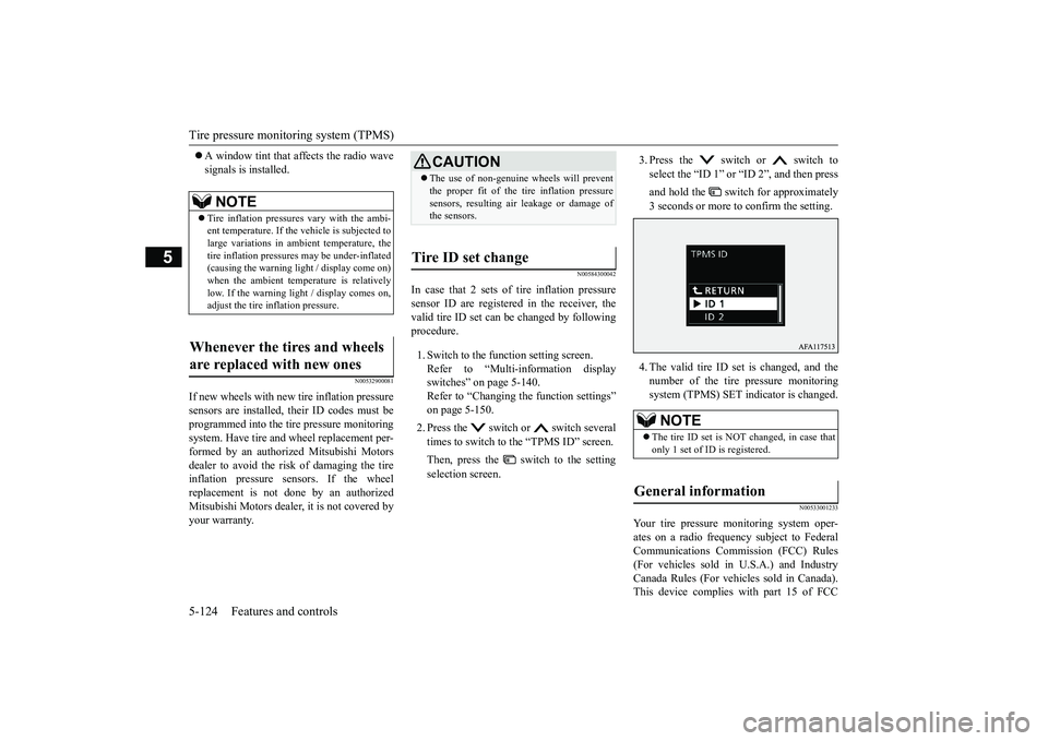
In case that 2 sets of tire inflation pressuresensor ID are registered in the receiver, the valid tire ID set can be changed by followingprocedure. 1. Switch to the function setting screen. Refer to “Multi-information display switches” on page 5-140.Refer to “Changing the function settings” on page 5-150. 2. Press the switch or switch several times to switch to the “TPMS ID” screen. Then, press the switch to the setting selection screen.
3. Press the switch or switch to select the “ID 1” or “ID 2”, and then press and hold the switch for approximately 3 seconds or more to confirm the setting. 4. The valid tire ID set is changed, and the number of the tire pressure monitoringsystem (TPMS) SET indicator is changed.
N00533001233
Your tire pressure monitoring system oper- ates on a radio frequency subject to Federal Communications Commission (FCC) Rules(For vehicles sold in U.S.A.) and Industry Canada Rules (For vehicles sold in Canada). This device complies with part 15 of FCC
NOTE
Tire inflation pressures vary with the ambi- ent temperature. If the
vehicle is subjected to
large variations in ambient temperature, thetire inflation pressures may be under-inflated (causing the warning light / display come on) when the ambient temperature is relativelylow. If the warning light / display comes on, adjust the tire inflation pressure.
Whenever the tires and wheels are replaced with new ones
CAUTION The use of non-genuine wheels will prevent the proper fit of the tire inflation pressure sensors, resulting air leakage or damage of the sensors.
Tire ID set change
NOTE
The tire ID set is NOT changed, in case that only 1 set of ID is registered.
General information
BK0266800US.book
124 ページ 2018年6月27日 水曜日 午後5時6分
Page 208 of 423
Rear-view camera
Features and controls 5-125
5
Rules and Industry Canada licence-exempt RSS standard(s). Operation is subject to the following two con- ditions. This device may not cause harmful inter- ference. This device must accept any interference received, including interference that maycause undesired operation.
N00546201330
When the selector lever is in the “R”(REVERSE) position with the ignition switchin the “ON” position, or the operation mode is put in ON, the rear-view image will be dis- played on the screen of the Smartphone LinkDisplay Audio. When the selector lever is shifted out of the “R” (REVERSE) position, the rear-viewimage will go off.
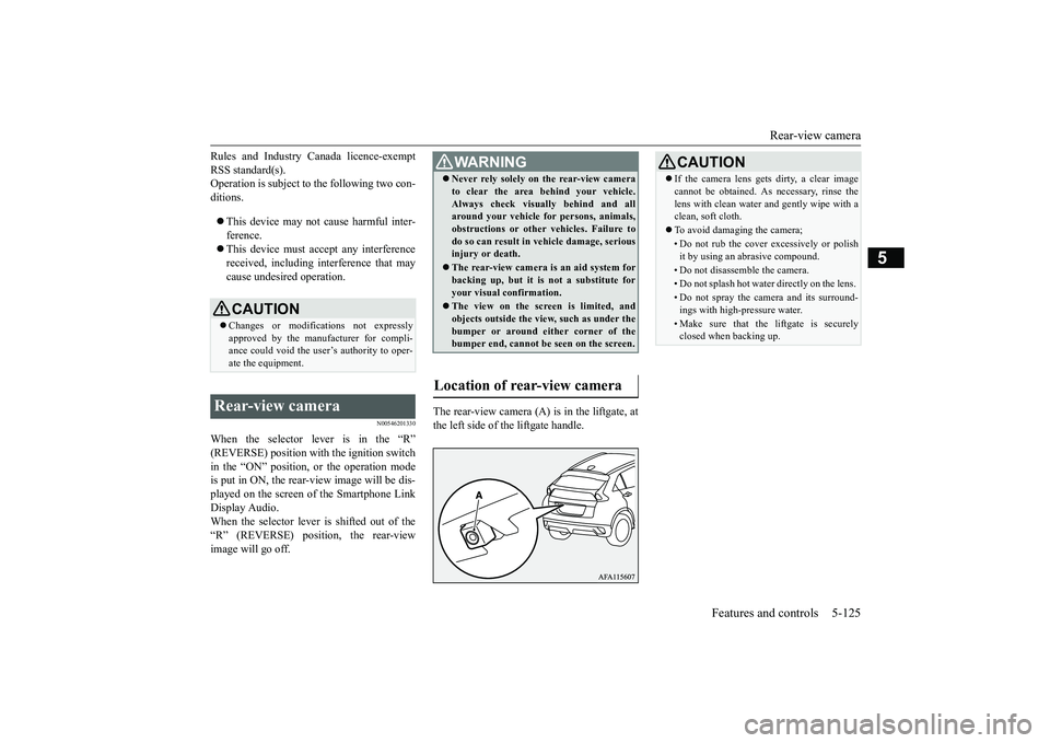
The rear-view camera (A) is in the liftgate, at the left side of the liftgate handle.
CAUTION Changes or modifications not expressly approved by the manufacturer for compli- ance could void the user’s authority to oper-ate the equipment.
Rear-view camera
WA R N I N G Never rely solely on the rear-view camera to clear the area behind your vehicle. Always check visually behind and all around your vehicle for persons, animals, obstructions or other vehicles. Failure todo so can result in vehicle damage, serious injury or death. The rear-view camera is an aid system for backing up, but it is not a substitute for your visual confirmation. The view on the screen is limited, and objects outside the view, such as under thebumper or around either corner of the bumper end, cannot be seen on the screen.
Location of rear-view camera
CAUTION If the camera lens gets dirty, a clear image cannot be obtained. As necessary, rinse the lens with clean water and gently wipe with a clean, soft cloth. To avoid damaging the camera;• Do not rub the cover excessively or polish it by using an abrasive compound. • Do not disassemble the camera.• Do not splash hot water directly on the lens. • Do not spray the camera and its surround- ings with high-pressure water.• Make sure that the liftgate is securelyclosed when backing up.
BK0266800US.book
125 ページ 2018年6月27日 水曜日 午後5時6分
Page 210 of 423
Multi Around Monitor (if so equipped)
Features and controls 5-127
5
N00587200068
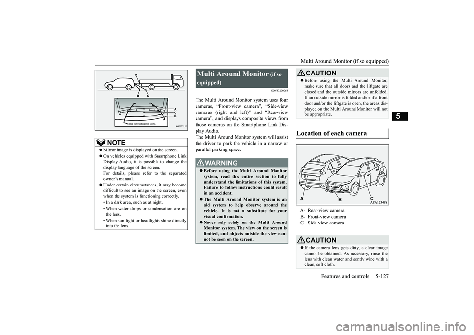
The Multi Around Monitor system uses four cameras, “Front-view camera”, “Side-view cameras (right and left)” and “Rear-view camera”, and displays composite views fromthose cameras on the Smartphone Link Dis- play Audio. The Multi Around Monitor system will assistthe driver to park the vehicle in a narrow orparallel parking space.
NOTE
Mirror image is displayed on the screen. On vehicles equipped with Smartphone Link Display Audio, it is possible to change the display language of the screen. For details, please refer to the separatedowner’s manual. Under certain circumstances, it may become difficult to see an image on the screen, even when the system is functioning correctly. • In a dark area, such as at night. • When water drops or condensation are on the lens. • When sun light or headlights shine directly into the lens.
Multi Around Monitor
(if so
equipped)
WA R N I N G Before using the Multi Around Monitor system, read this entire section to fully understand the limitations of this system. Failure to follow instructions could resultin an accident. The Multi Around Monitor system is an aid system to help observe around the vehicle. It is not a substitute for your visual confirmation. Never rely solely on the Multi Around Monitor system. The view on the screen is limited, and objects outside the view can- not be seen on the screen.
CAUTION Before using the Multi Around Monitor, make sure that all doors and the liftgate are closed and the outside mirrors are unfolded. If an outside mirror is folded and/or if a front door and/or the liftgate is open, the areas dis-played on the Multi Around Monitor will not be appropriate.
Location of each camera
A- Rear-view camera B- Front-view camera C- Side-view cameraCAUTION If the camera lens gets dirty, a clear image cannot be obtained. As necessary, rinse the lens with clean water and gently wipe with aclean, soft cloth.
BK0266800US.book
127 ページ 2018年6月27日 水曜日 午後5時6分
Page 214 of 423
Multi Around Monitor (if so equipped)
Features and controls 5-131
5
N00587500074
The Multi Around Monitor can only be used when the operation mode is put in ON. When you move the selector lever to the “R” (REVERSE) position, the bird’s eye-view/rear-view is displayed on the Smart- phone Link Display A
udio. When you move
the selector lever to any other position, thedisplay disappears.
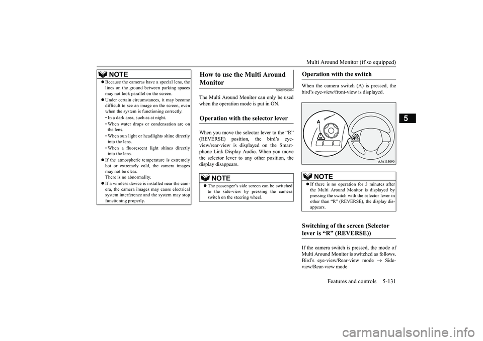
When the camera switch (A) is pressed, the bird’s eye-view/front-view is displayed. If the camera switch is pressed, the mode of Multi Around Monitor is switched as follows.Bird’s eye-view/Rear-view mode
Side-
view/Rear-view mode
NOTE
Because the cameras have a special lens, the lines on the ground between parking spaces may not look parallel on the screen. Under certain circumstances, it may become difficult to see an image on the screen, even when the system is functioning correctly. • In a dark area, such as at night. • When water drops or condensation are on the lens. • When sun light or headlights shine directly into the lens. • When a fluorescent light shines directly into the lens.
If the atmospheric temperature is extremely hot or extremely cold, the camera images may not be clear. There is no abnormality. If a wireless device is installed near the cam- era, the camera images may cause electricalsystem interference and the system may stop functioning properly.
How to use the Multi Around Monitor
Operation with the selector lever
NOTE
The passenger’s side screen can be switched to the side-view by pressing the camera switch on the steering wheel.
Operation with the switch
NOTE
If there is no operation for 3 minutes after the Multi Around Monitor is displayed bypressing the switch with the selector lever in other than “R” (REVERSE), the display dis- appears.
Switching of the screen (Selector lever is “R” (REVERSE))
BK0266800US.book
131 ページ 2018年6月27日 水曜日 午後5時6分
Page 215 of 423
Multi Around Monitor (if so equipped) 5-132 Features and controls
5
If the camera switch is pressed, the mode of Multi Around Monitor is switched, Bird’s eye-view/Front-view mode
Side-
view/Front-view mode
OFF
N00587600059
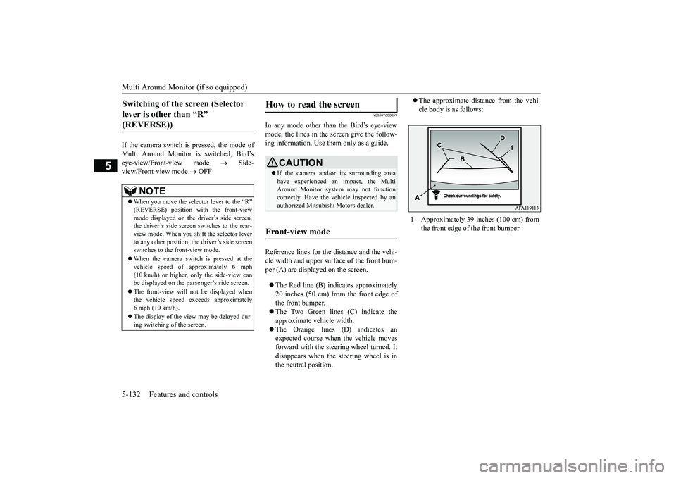
In any mode other than the Bird’s eye-view mode, the lines in the screen give the follow-ing information. Use them only as a guide. Reference lines for the distance and the vehi- cle width and upper surface of the front bum- per (A) are displayed on the screen. The Red line (B) indicates approximately 20 inches (50 cm) from the front edge of the front bumper. The Two Green lines (C) indicate the approximate vehicle width. The Orange lines (D) indicates an expected course when the vehicle movesforward with the steering wheel turned. It disappears when the steering wheel is in the neutral position.
The approximate distance from the vehi- cle body is as follows:
Switching of the screen (Selector lever is other than “R” (REVERSE))
NOTE
When you move the selector lever to the “R” (REVERSE) position with the front-viewmode displayed on the driver’s side screen, the driver’s side screen switches to the rear- view mode. When you shift the selector leverto any other position, the driver’s side screen switches to the front-view mode. When the camera switch is pressed at the vehicle speed of approximately 6 mph (10 km/h) or higher, only the side-view canbe displayed on the passenger’s side screen. The front-view will not be displayed when the vehicle speed exceeds approximately 6 mph (10 km/h). The display of the view may be delayed dur- ing switching of the screen.
How to read the screen
CAUTION If the camera and/or its surrounding area have experienced an impact, the Multi Around Monitor system may not functioncorrectly. Have the vehicle inspected by an authorized Mitsubishi Motors dealer.
Front-view mode
1- Approximately 39 inches (100 cm) from
the front edge of the front bumper
BK0266800US.book
132 ページ 2018年6月27日 水曜日 午後5時6分
Page 223 of 423
![MITSUBISHI ECLIPSE CROSS 2019 Owners Manual (in English) Multi-information display 5-140 Features and controls
5
[With ignition switch or operation mode in ON]
N00555101234
Each time the multi-information display switches are operated, the buzzer sounds and MITSUBISHI ECLIPSE CROSS 2019 Owners Manual (in English) Multi-information display 5-140 Features and controls
5
[With ignition switch or operation mode in ON]
N00555101234
Each time the multi-information display switches are operated, the buzzer sounds and](/img/19/34870/w960_34870-222.png)
Multi-information display 5-140 Features and controls
5
[With ignition switch or operation mode in ON]
N00555101234
Each time the multi-information display switches are operated, the buzzer sounds andthe multi-information display changes
1- S-AWC drive mode display screen (if
so equipped)
P.5-67
2-
Warning display screen
P.5-144
3- Lane Departure Warning (LDW) dis-
play screen (if so equipped)
P.5-117
4- ECO mode indicator display screen
P.5-196
5- Information screen
P.5-141
6- Selector lever position display
P.5-61
7- Engine coolant temperature display
P.5-145
8- Odometer
P.5-146
9- Cruise control display screen
P.5-82
10- Adaptive Cruise Control System (ACC)
display screen (if so equipped) P.5-87
11- ECO indicator
P.5-149
12-
“ ” mark indicator
P.5-144
13- Fuel remaining display screen
P.5-145
14- Outside temperature display screen
P.5-146
NOTE
The fuel units, outside temperature units, display language, and other settings can be changed. Refer to “Changing the function settings” on page 5-150.
Multi-information display switches
BK0266800US.book
140 ページ 2018年6月27日 水曜日 午後5時6分
Page 225 of 423
Multi-information display 5-142 Features and controls
5
N00555801260
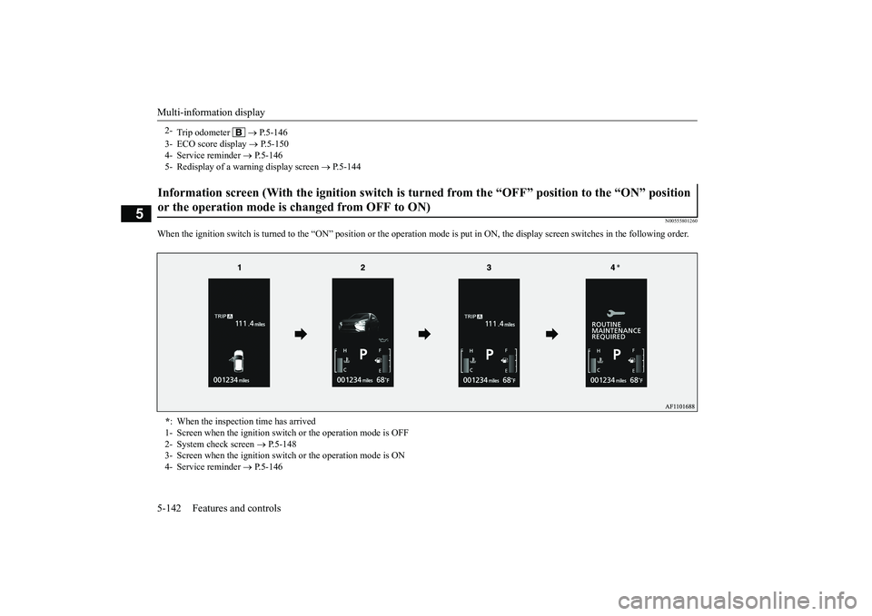
When the ignition switch is turned to the
“ON” position or the operation mode is put
in ON, the display screen switches in the
following order.
2-
Trip odometer
P.5-146
3- ECO score display
P.5-150
4- Service reminder
P.5-146
5- Redisplay of a warning display screen
P.5-144
Information screen (With the ignition switch is turned from the “OFF” position to the “ON” position or the operation mode is changed from OFF to ON) * : When the inspection time has arrived 1- Screen when the ignition switch or the operation mode is OFF 2- System check screen
P.5-148
3- Screen when the ignition switch or the operation mode is ON4- Service reminder
P.5-146
BK0266800US.book
142 ページ 2018年6月27日 水曜日 午後5時6分
Page 227 of 423
Multi-information display 5-144 Features and controls
5
N00556301246
When there is information to be announced, such as a system fault, the tone sounds and the information screen is switched to thewarning display screen. Refer to the warning list and take the neces- sary measures. Refer to “Warning display list” on page 5-160. When the cause of the warning display iseliminated, the warning display goes out automatically.
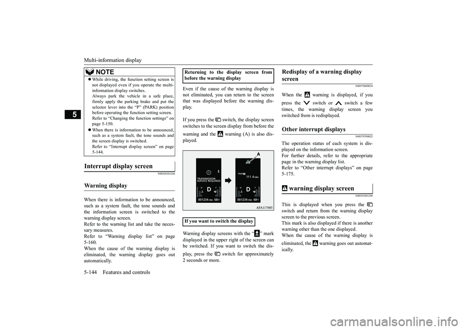
Even if the cause of the warning display is not eliminated, you can return to the screen that was displayed before the warning dis-play. If you press the switch, the display screen switches to the screen display from before the warning and the warning (A) is also dis- played. Warning display screens with the “ ” mark displayed in the upper right of the screen can be switched. If you want to switch the dis- play, press the switch for approximately 2 seconds or more.
N00579600034
When the warning is displayed, if you press the switch or switch a few times, the warning display screen you switched from is redisplayed.
N00579700022
The operation status of each system is dis- played on the information screen. For further details, refer to the appropriatepage in the warning display list. Refer to “Other interrupt displays” on page 5-175.
N00555201248
This is displayed when you press the switch and return from the warning display screen to the previous screen.This mark is also displayed if there is another warning other than the one displayed. When the cause of the warning display is eliminated, the warning goes out automat- ically.
While driving, the function setting screen is not displayed even if you operate the multi- information display switches. Always park the vehicle in a safe place, firmly apply the parking brake and put theselector lever into the “P” (PARK) position before operating the function setting screen. Refer to “Changing the function settings” onpage 5-150. When there is information to be announced, such as a system fault, the tone sounds and the screen display is switched. Refer to “Interrupt display screen” on page5-144.
Interrupt display screen Warning display
NOTE
Returning to the display screen from before the warning display If you want to switch the display
Redisplay of a warning display screen Other interrupt displays warning display screen
BK0266800US.book
144 ページ 2018年6月27日 水曜日 午後5時6分
Page 230 of 423
Multi-information display
Features and controls 5-147
5
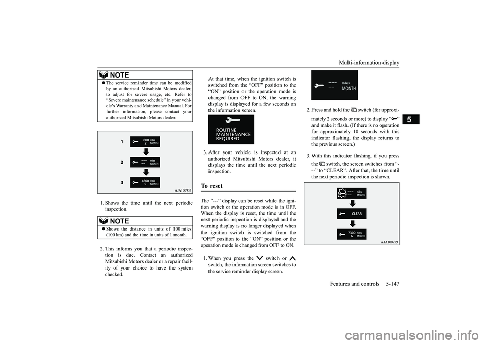
1. Shows the time until the next periodic inspection. 2. This informs you that a periodic inspec- tion is due. Contact an authorized Mitsubishi Motors dealer or a repair facil-ity of your choice to have the system checked.
At that time, when the ignition switch is switched from the “OFF” position to the “ON” position or the operation mode ischanged from OFF to ON, the warning display is displayed for a few seconds on the information screen. 3. After your vehicle is inspected at an authorized Mitsubishi Motors dealer, it displays the time until the next periodic inspection.
The “---” display can be reset while the igni- tion switch or the operation mode is in OFF.When the display is reset, the time until the next periodic inspection is displayed and the warning display is no longer displayed whenthe ignition switch is switched from the “OFF” position to the “ON” position or the operation mode is changed from OFF to ON. 1. When you press the switch or switch, the information screen switches to the service reminder display screen.
2. Press and hold the switch (for approxi- mately 2 seconds or
more) to display “ ”
and make it flash. (If there is no operation for approximately 10 seconds with this indicator flashing, the display returns tothe previous screen.) 3. With this indicator flashing, if you press the switch, the screen switches from “- --” to “CLEAR”. After that, the time until the next periodic inspection is shown.
NOTE
The service reminder time can be modified by an authorized Mitsubishi Motors dealer, to adjust for severe usage, etc. Refer to “Severe maintenance schedule” in your vehi- cle’s Warranty and Maintenance Manual. Forfurther information, please contact your authorized Mitsubishi Motors dealer.NOTE
Shows the distance in units of 100 miles (100 km) and the time in units of 1 month.
To r e s e t
BK0266800US.book
147 ページ 2018年6月27日 水曜日 午後5時6分