steering MITSUBISHI ECLIPSE CROSS 2020 (in English) Owner's Guide
[x] Cancel search | Manufacturer: MITSUBISHI, Model Year: 2020, Model line: ECLIPSE CROSS, Model: MITSUBISHI ECLIPSE CROSS 2020Pages: 427, PDF Size: 78.05 MB
Page 236 of 427
Multi-information display
Features and controls 5-155
5
N00578800055
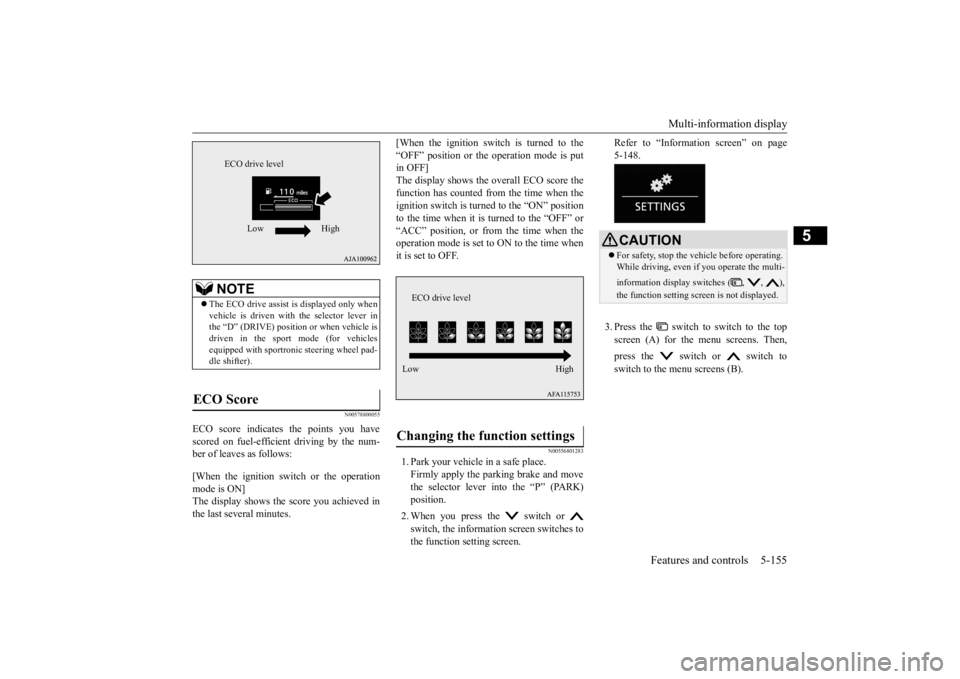
ECO score indicates
the points you have
scored on fuel-efficient driving by the num- ber of leaves as follows: [When the ignition switch or the operation mode is ON]The display shows the score you achieved in the last several minutes.
[When the ignition switch is turned to the “OFF” position or the operation mode is put in OFF] The display shows the overall ECO score thefunction has counted from the time when the ignition switch is turned to the “ON” position to the time when it is turned to the “OFF” or“ACC” position, or from the time when the operation mode is set to ON to the time when it is set to OFF.
N00556801283
1. Park your vehicle in a safe place.Firmly apply the parking brake and movethe selector lever into the “P” (PARK) position. 2. When you press the switch or switch, the information screen switches to the function setting screen.
Refer to “Information screen” on page 5-148. 3. Press the switch to switch to the top screen (A) for the menu screens. Then, press the switch or switch to switch to the menu screens (B).
NOTE
The ECO drive assist is displayed only when vehicle is driven with the selector lever in the “D” (DRIVE) position or when vehicle isdriven in the sport mode (for vehicles equipped with sportronic steering wheel pad- dle shifter).
ECO Score
ECO drive level
Low High
Changing the function settings
ECO drive level Low High
CAUTION For safety, stop the vehicle before operating. While driving, even if you operate the multi- information display switches ( , , ), the function setting scr
een is not displayed.
BK0277700US.book
155 ページ 2019年3月8日 金曜日 午前9時23分
Page 244 of 427
Indicator light, warning light, an
d information screen display list Features and controls 5-163
5
N00557701090 N00557801411
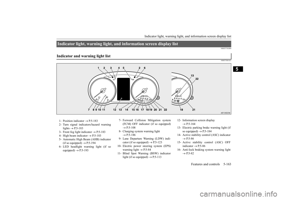
Indicator light, warning light, and information screen display list Indicator and warning light list 1- Position indicator
P.5-183
2- Turn signal indicators/hazard warning
lights
P.5-183
3- Front fog light indicator
P.5-183
4- High beam indicator
P.5-183
5- Automatic High Beam (AHB) indicator
(if so equipped)
P.5-194
6- LED headlight warning light (if so
equipped)
P.5-193
7- Forward Collision Mitigation system
(FCM) OFF indicator (if so equipped) P.5-108
8- Charging system warning light
P.5-186
9- Lane Departure Warning (LDW) indi-
cator (if so equipped)
P.5-123
10- Electric power steering system (EPS)
warning light
P.5-84
11- Blind Spot Warning (BSW) indicator
light (if so equipped)
P.5-113
12- Information screen display
P.5-164
13- Electric parking brake warning light (if
so equipped)
P.5-184
14- Active stability control (ASC) indicator
P.5-86
15- Active stability control (ASC) OFF
indicator
P.5-86
16- Anti-lock braking system warning light
P.5-82
BK0277700US.book
163 ページ 2019年3月8日 金曜日 午前9時23分
Page 248 of 427
Indicator light, warning light, an
d information screen display list Features and controls 5-167
5
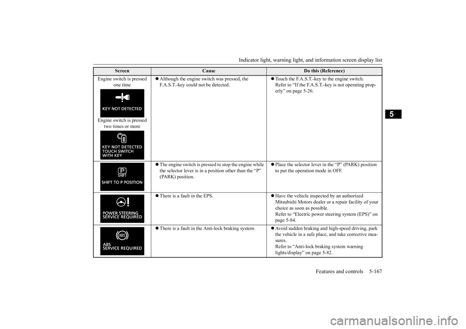
Engine switch is pressed
one time
Engine switch is pressed
two times or more
Although the engine switch was pressed, the F.A.S.T.-key could not be detected.
Touch the F.A.S.T.-key to the engine switch. Refer to “If the F.A.S.T.-key is not operating prop- erly” on page 5-26.
The engine switch is pressed to stop the engine while the selector lever is in a position other than the “P” (PARK) position.
Place the selector lever in the “P” (PARK) position to put the operation mode in OFF.
There is a fault in the EPS.
Have the vehicle inspected by an authorized Mitsubishi Motors dealer or a repair facility of your choice as soon as possible. Refer to “Electric power steering system (EPS)” on page 5-84.
There is a fault in the Anti-lock braking system.
Avoid sudden braking and high-speed driving, park the vehicle in a safe place, and take corrective mea- sures. Refer to “Anti-lock braking system warning lights/display” on page 5-82.
Screen
Cause
Do this (Reference)
BK0277700US.book
167 ページ 2019年3月8日 金曜日 午前9時23分
Page 281 of 427
Hazard warning flasher switch 5-200 Features and controls
5
tion (1). It will return to the neutral position when you let go. Use the full position (2) when making a normal turn. The lever will return to the neutral position when the turn iscomplete. There may be times when the lever does not return to the neutral position. This usually happens when the steering wheel isturned only slightly. You can easily return the lever by hand. Also, when you move the lever to (1) slightlythen release it, the turn signal lights and theindicator light in the instrument cluster will flash three times.
N00522701344
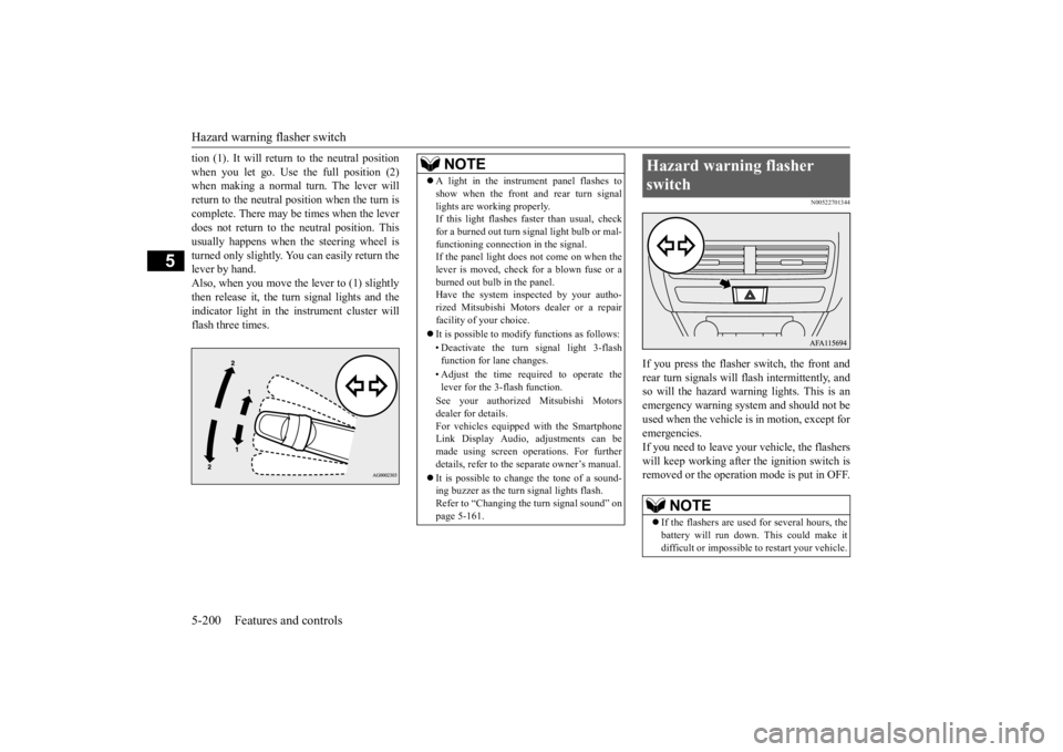
If you press the flasher switch, the front and rear turn signals will flash intermittently, and so will the hazard warn
ing lights. This is an
emergency warning system and should not beused when the vehicle is in motion, except foremergencies. If you need to leave your vehicle, the flashers will keep working after the ignition switch isremoved or the operation mode is put in OFF.
NOTE
A light in the instrument panel flashes to show when the front and rear turn signal lights are working properly. If this light flashes faster than usual, check for a burned out turn signal light bulb or mal-functioning connection in the signal. If the panel light does not come on when the lever is moved, check for a blown fuse or aburned out bulb in the panel. Have the system inspected by your autho- rized Mitsubishi Motors dealer or a repairfacility of your choice. It is possible to modify functions as follows: • Deactivate the turn signal light 3-flash function for lane changes. • Adjust the time required to operate the lever for the 3-flash function. See your authorized Mitsubishi Motors dealer for details.For vehicles equipped with the Smartphone Link Display Audio, adjustments can be made using screen operations. For furtherdetails, refer to the separate owner’s manual. It is possible to change the tone of a sound- ing buzzer as the turn signal lights flash. Refer to “Changing the turn signal sound” on page 5-161.
Hazard warning flasher switch
NOTE
If the flashers are used for several hours, the battery will run down. This could make it difficult or impossible to restart your vehicle.
BK0277700US.book
200 ページ 2019年3月8日 金曜日 午前9時23分
Page 289 of 427
Heated steering wheel switch (if so equipped) 5-208 Features and controls
5
N00589100045
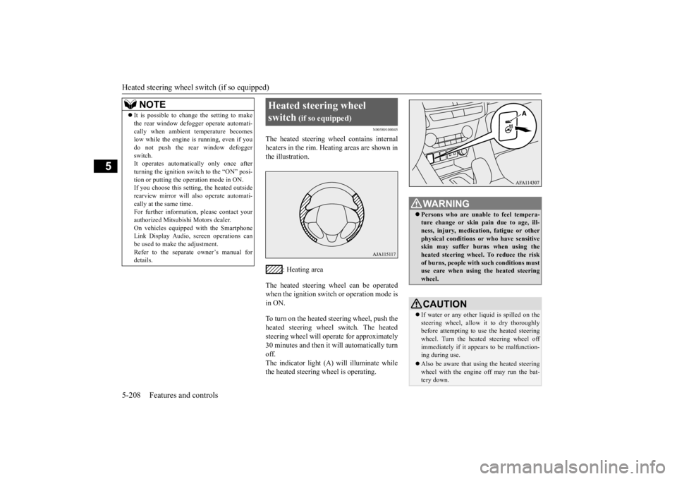
The heated steering wheel contains internal heaters in the rim. Heating areas are shown inthe illustration.
: Heating area
The heated steering wheel can be operated when the ignition switch or operation mode is in ON. To turn on the heated steering wheel, push the heated steering wheel switch. The heatedsteering wheel will operate for approximately 30 minutes and then it will automatically turn off.The indicator light (A) will illuminate while the heated steering wheel is operating.
It is possible to change the setting to make the rear window defogger operate automati- cally when ambient temperature becomes low while the engine is running, even if you do not push the rear window defoggerswitch. It operates automatically only once after turning the ignition switch to the “ON” posi-tion or putting the operation mode in ON. If you choose this setting, the heated outside rearview mirror will also operate automati-cally at the same time. For further information, please contact your authorized Mitsubishi Motors dealer.On vehicles equipped with the Smartphone Link Display Audio, screen operations can be used to make the adjustment.Refer to the separate owner’s manual for details.NOTE
Heated steering wheel switch
(if so equipped)
WA R N I N G Persons who are unable to feel tempera- ture change or skin pain due to age, ill- ness, injury, medication, fatigue or other physical conditions or who have sensitiveskin may suffer burns when using the heated steering wheel. To reduce the risk of burns, people with such conditions mustuse care when using the heated steering wheel.CAUTION If water or any other li
quid is spilled on the
steering wheel, allow it to dry thoroughly before attempting to use the heated steering wheel. Turn the heated steering wheel offimmediately if it appears to be malfunction- ing during use. Also be aware that using the heated steering wheel with the engine off may run the bat- tery down.
BK0277700US.book
208 ページ 2019年3月8日 金曜日 午前9時23分
Page 290 of 427
Horn switch
Features and controls 5-209
5
N00523801195
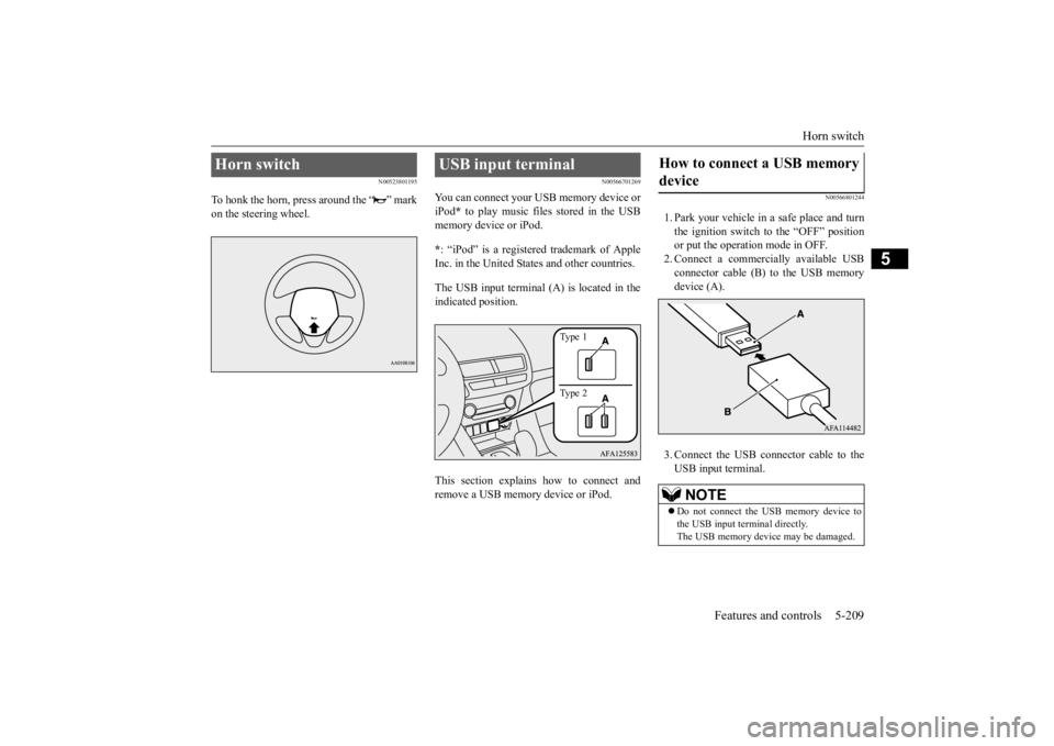
To honk the horn, press around the “ ” mark on the steering wheel.
N00566701269
You can connect your USB memory device or iPod
* to play music files stored in the USB
memory device or iPod. * : “iPod” is a registered trademark of Apple Inc. in the United States and other countries. The USB input terminal (A) is located in the indicated position. This section explains how to connect and remove a USB memory device or iPod.
N00566801244
1. Park your vehicle in a safe place and turn the ignition switch to the “OFF” position or put the operation mode in OFF.2. Connect a commercially available USB connector cable (B) to the USB memory device (A). 3. Connect the USB connector cable to the USB input terminal.
Horn switch
USB input terminal
Type 1 Type 2
How to connect a USB memory device
NOTE
Do not connect the USB memory device to the USB input terminal directly.The USB memory device may be damaged.
BK0277700US.book
209 ページ 2019年3月8日 金曜日 午前9時23分
Page 313 of 427
Vehicle preparation before driving 6-4 Driving safety
6
N00629001842
For a safer and more enjoyable trip, always check for the following: Before starting the vehicle, make certain that you and all passengers are seated and wearing their seat belts properly (with children in the rear seat, in appropriaterestraints), and that all the doors and the liftgate are locked. Move the driver’s seat as far backward as possible, while keeping good visibility, and good control of the steering wheel, brakes, accelerator, and controls. Checkthe instrument panel indicators and multi- information display for any possible prob- lem. Similarly, the front passenger seat should also be moved as far back as possible. Make sure that infants and small children are properly restrained in accordance with all laws and regulations.
Check these by selecting the defroster mode, and set the blower switch on high. You shouldbe able to feel the air blowing against the windshield. Refer to “Defrosting or defogging (wind-shield, door windows)” on page 7-13, 7-22. Check all the tires for heavy tread wear or uneven wear patterns. Look for stones, nails,glass, or other objects stuck in the tread. Look for any tread cuts or sidewall cracks. Check the wheel nuts for tightness, and the tires(including spare tire) for proper pressure. Replace your tires before they are heavily worn out.As your vehicle is equipped with a tire pres- sure monitoring system, there is a risk of damage to the tire inflation pressure sensorswhen the tire is replaced on the rim. Tire replacement should, only, be performed by an authorized Mitsubishi Motors dealer. Have someone watch while you turn all the exterior lights on and off. Also check the turn
signal indicators and high-beam indicators on the instrument panel. Check the ground under the vehicle after parking overnight, for fuel, water, oil, or other leaks. Make sure all the fluid levels are correct. Also, if you can smell fuel, you needto find out why immediately and have itfixed.
N00629201147
Even this vehicle’s safety equipment, andyour safest driving, cannot guarantee that you can avoid an accident or injury. However, if you give extra attention to the followingareas, you can better protect yourself and your passengers: Drive defensively. Be aware of traffic, road and weather conditions. Leave plentyof stopping distance between your vehicle and the vehicle ahead. Before changing lanes, check your mir- rors, blind spots, and use your turn signal light. While driving, watch the behavior of other drivers, bicyclists, and pedestrians.
Vehicle preparation before driving Seat belts and seats
Defrosters Tires Lights
Fluid leaks Safe driving techniques
BK0277700US.bo
ok 4 ページ 2019年3月8日 金曜日 午前9時23分
Page 315 of 427
Parking 6-6 Driving safety
6
N00629601398
When parking on a hill, set the parking brake, and turn the front wheels toward the curb on adownhill, or away from the curb on an uphill. If necessary, apply chocks to the wheels. Be sure that the parking brake is firmly setwhen parked and that the selector lever is inthe “P” (PARK) position. When parking on a hill, it is important to set the parking brake before moving the selectorlever to the “P” (PARK) position. This pre- vents loading the parking brake against the transaxle. When this happens, it is difficult tomove the selector lever out of the “P” (PARK) position. Never leave the engi
ne running while you
take a short nap or rest. Also, never leave theengine running in a closed or poorly venti- lated place.
Your front bumper can be damaged if you scrape it over curbs or parking stop blocks. Be careful when traveling up or down steep slopes where your bumper can scrape theroad. Always carry the key and lock all doors and the liftgate when leaving the vehicle unat- tended. Always try to park your vehicle in a well litarea.
More effort could be required to turn the steering wheel. Refer to “Electric power steering system (EPS)” on page 5-84.
N00629901450
It is very important to know how much weight your vehicle can carry. This weight is called the vehicle capacity weight andincludes the weight of all occupants, cargo (including the roof load), non-factory- installed options, and the tongue weight ofthe trailer, if any, being towed. The tire and loading information placard located on the driver’s door sill of your vehicle will showhow much weight it may properly carry. It is important to familiarize yourself with the following terms before loading your vehicle:
Parking Parking on a hill Parking with the engine run- ning
WA R N I N G Leaving the engine running risks injury or death from accidentally moving the selec- tor lever or the accumulation of toxic exhaust fumes in the passenger compart- ment.
Where you park
WA R N I N G Do not park your vehicle in areas where combustible materials such as dry grass or leaves can come in contact with a hot exhaust, since a fire could occur.
When leaving the vehicle
Do not keep the steering wheel fully turned for a long time Loading information
WA R N I N G Never overload your vehicle. Overloading can damage your vehicle, adversely affect vehicle performance, including handlingand braking, cause tire failure, and result in an accident.
BK0277700US.bo
ok 6 ページ 2019年3月8日 金曜日 午前9時23分
Page 316 of 427
Loading information Driving safety 6-7
6
Vehicle maximum load on the tire: load on an individual tire that is determined by distributing to each axle its share of the maximum loaded vehicle weight anddividing by two. Vehicle normal load on the tire: load on an individual tire that is determined by dis-tributing to each axle its share of the curb weight, accessory weight, and normal occupant weight and dividing by two. Maximum loaded vehicle weight: the sum of - (a) Curb weight; (b) Accessory weight;(c) Vehicle capacity weight; and (d) Production options weight. Curb weight: the weight of a motor vehi- cle with standard equipment including the maximum capacity of fuel, oil, and cool- ant. Accessory weight: the combined weight (in excess of those standard items which may be replaced) of automatic transaxle,power steering, power brakes, power win- dows, power seats, radio, and heater, to the extent that these items are available asfactory-installed equipment (whether installed or not). Vehicle capacity weight: the rated cargo and luggage load plus 150 lbs (68 kg) * times the vehicle’s designated seating capacity.
Production options weight: the combined weight of those installed regular produc- tion options weighing over 5 lbs (2.3 kg) in excess of those standard items whichthey replace, not previously considered in curb weight or accessory weight, includ- ing heavy duty brakes, ride levelers, roofrack, heavy duty battery, and special trim. Normal occupant weight: 150 lbs (68 kg) * times the number of specified occupants (3 in the case of your vehicle) Occupant distribution: Occupant distribu- tion within the passenger compartment (In your vehicle the distribution is 2 in front,1 in rear seat)
N00630101423
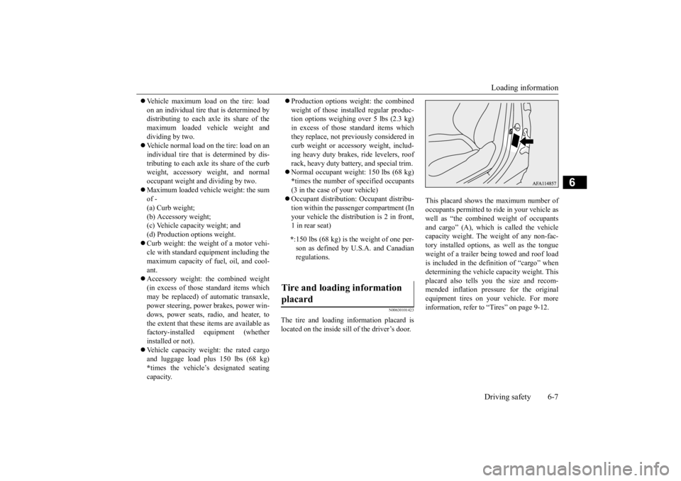
The tire and loading information placard is located on the inside sill of the driver’s door.
This placard shows the maximum number of occupants permitted to ride in your vehicle aswell as “the combined weight of occupants and cargo” (A), which is called the vehicle capacity weight. The weight of any non-fac-tory installed options, as well as the tongue weight of a trailer being towed and roof load is included in the definition of “cargo” whendetermining the vehicle capacity weight. Thisplacard also tells you the size and recom- mended inflation pressure for the original equipment tires on your vehicle. For moreinformation, refer to “Tires” on page 9-12.
* :150 lbs (68 kg) is the weight of one per- son as defined by U.S.A. and Canadianregulations.
Tire and loading information placard
BK0277700US.bo
ok 7 ページ 2019年3月8日 金曜日 午前9時23分
Page 320 of 427
Trailer towing
Driving safety 6-11
6
N00629801387
Towing a trailer will adversely affect your vehicle’s handling, performance, braking,durability and driving economy (fuel con- sumption, etc.). If you do tow a trailer with this vehicle, besure to use proper equipment and cautious steering and braking for safe driving.
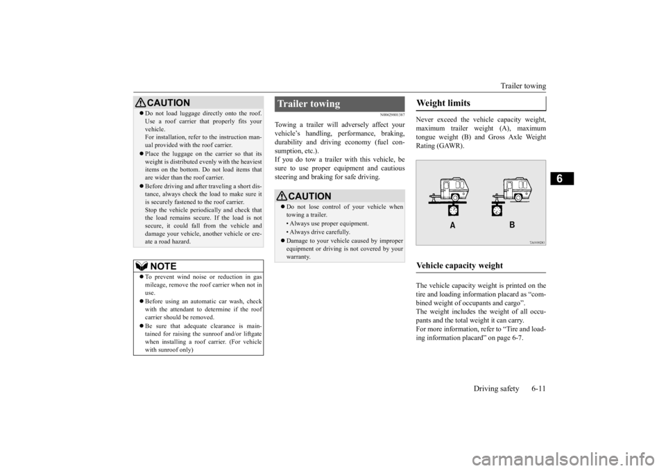
Never exceed the vehicle capacity weight, maximum trailer weight (A), maximum tongue weight (B) and Gross Axle WeightRating (GAWR). The vehicle capacity weight is printed on the tire and loading information placard as “com- bined weight of occupants and cargo”.The weight includes the weight of all occu- pants and the total weight it can carry. For more information, refer to “Tire and load-ing information placard” on page 6-7.
CAUTION Do not load luggage directly onto the roof. Use a roof carrier th
at properly fits your
vehicle. For installation, refer to the instruction man- ual provided with the roof carrier. Place the luggage on the carrier so that its weight is distributed evenly with the heaviestitems on the bottom. Do not load items that are wider than the roof carrier. Before driving and after traveling a short dis- tance, always check the load to make sure it is securely fastened to the roof carrier.Stop the vehicle periodically and check that the load remains secure. If the load is not secure, it could fall from the vehicle anddamage your vehicle, another vehicle or cre- ate a road hazard.NOTE
To prevent wind noise or reduction in gas mileage, remove the roof carrier when not in use. Before using an automatic car wash, check with the attendant to determine if the roof carrier should be removed. Be sure that adequate clearance is main- tained for raising the sunroof and/or liftgate when installing a roof carrier. (For vehicle with sunroof only)
Trailer towing
CAUTION Do not lose control of your vehicle when towing a trailer.• Always use proper equipment.• Always drive carefully. Damage to your vehicle caused by improper equipment or driving is not covered by your warranty.
Weight limits Vehicle capacity weight
BK0277700US.bo
ok 11 ページ 2019年3月8日 金曜日 午前9時23分