MITSUBISHI ENDEAVOR 2004 Service Repair Manual
ENDEAVOR 2004
MITSUBISHI
MITSUBISHI
https://www.carmanualsonline.info/img/19/57105/w960_57105-0.png
MITSUBISHI ENDEAVOR 2004 Service Repair Manual
Trending: Service engine light, CD player, steering wheel, Filter, clock setting, recommended oil, Egr valve
Page 1671 of 3870
TECHNICAL DESCRIPTION (COMMENT
)
Refer to INSPECTION PROCEDURE 2
.
TROUBLESHOOTING HINTS Refer to INSPECTION PROCEDURE 2
.
DIAGNOSIS Required Special Tool:
MB991223: Harness set
STEP 1. Measure the resistance at remote controlled radio switch (LH).
1. Remove the airbag module (Refer to AIR BAG RESTRAINT
SYSTEMS
).
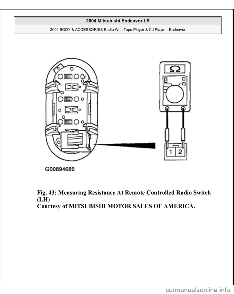
2. Measure the resistance by operating the remote controlled radio switch
(LH
) in each
position.
2004 Mitsubishi Endeavor LS
2004 BODY & ACCESSORIES Radio With Tape Player & Cd Player - Endeavor
Page 1672 of 3870
Fig. 43: Measuring Resistance At Remote Controlled Radio Switch (LH)
Courtesy of MITSUBISHI MOTOR SALES OF AMERICA.
2004 Mitsubishi Endeavor LS
2004 BODY & ACCESSORIES Radio With Tape Player & Cd Player - Endeavor
Page 1673 of 3870
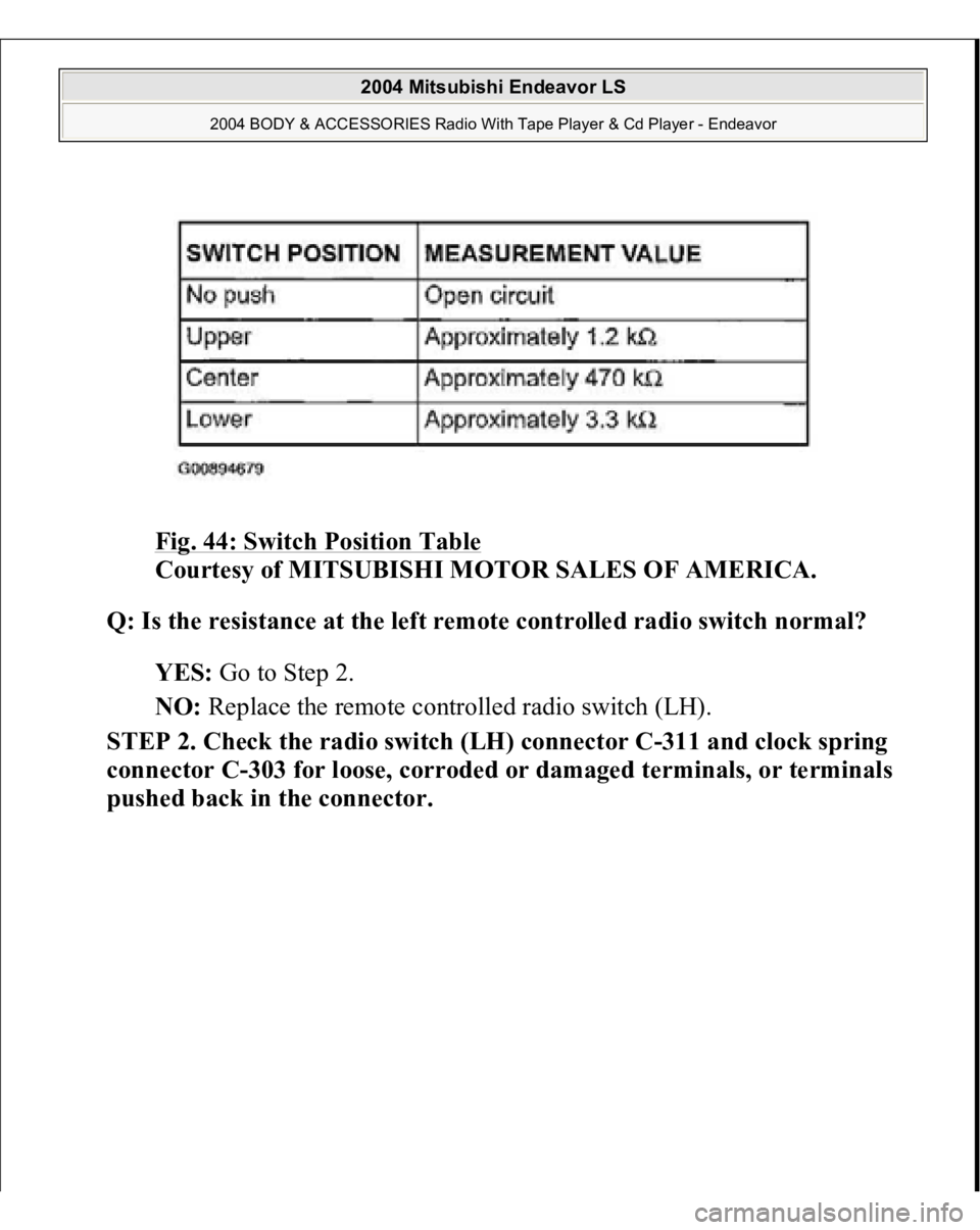
Fig. 44: Switch Position Table
Courtesy of MITSUBISHI MOTOR SALES OF AMERICA.
Q: Is the resistance at the left remote controlled radio switch normal?
YES: Go to Step 2.
NO: Replace the remote controlled radio switch (LH).
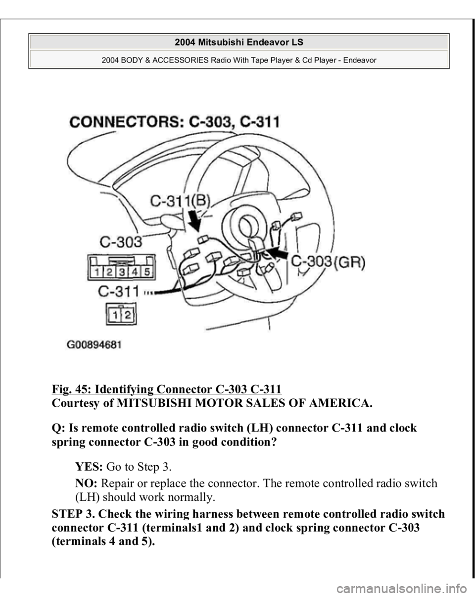
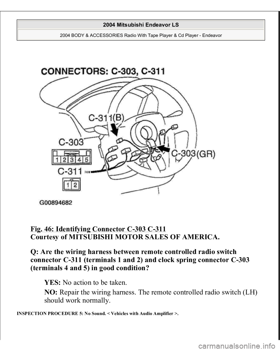
STEP 2. Check the radio switch (LH) connector C-311 and clock spring
connector C-303 for loose, corroded or damaged terminals, or terminals
pushed back in the connector.
2004 Mitsubishi Endeavor LS
2004 BODY & ACCESSORIES Radio With Tape Player & Cd Player - Endeavor
Page 1674 of 3870
Fig. 45: Identifying Connector C
-303 C
-311
Courtesy of MITSUBISHI MOTOR SALES OF AMERICA.
Q: Is remote controlled radio switch (LH) connector C-311 and clock
spring connector C-303 in good condition?
YES: Go to Step 3.
NO: Repair or replace the connector. The remote controlled radio switch
(LH) should work normally.
STEP 3. Check the wirin
g harness between remote controlled radio switch
connector C-311 (terminals1 and 2) and clock spring connector C-303
(terminals 4 and 5).
2004 Mitsubishi Endeavor LS
2004 BODY & ACCESSORIES Radio With Tape Player & Cd Player - Endeavor
Page 1675 of 3870
Fig. 46: Identifying Connector C
-303 C
-311
Courtesy of MITSUBISHI MOTOR SALES OF AMERICA.
Q: Are the wiring harness between remote controlled radio switch
connector C-311 (terminals 1 and 2) and clock spring connector C-303
(terminals 4 and 5) in good condition?
YES: No action to be taken.
NO: Repair the wiring harness. The remote controlled radio switch (LH)
should work normally.
INSPECTION PROCEDURE 5: No Sound. < Vehicles with Audio Amplifier >.
2004 Mitsubishi Endeavor LS
2004 BODY & ACCESSORIES Radio With Tape Player & Cd Player - Endeavor
Page 1676 of 3870
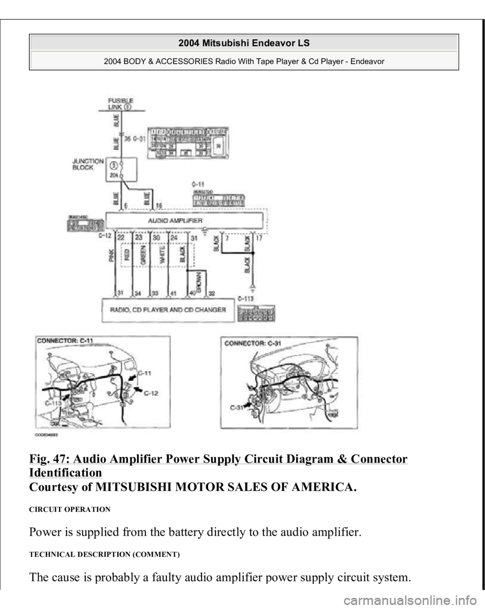
Fig. 47: Audio Amplifier Power Supply Circuit Diagram & Connector Identification
Courtesy of MITSUBISHI MOTOR SALES OF AMERICA.
CIRCUIT OPERATION Power is supplied from the battery directly to the audio amplifier. TECHNICAL DESCRIPTION (COMMENT) The cause is
probabl
y a fault
y audio am
plifier
power su
pply circuit s
ystem.
2004 Mitsubishi Endeavor LS
2004 BODY & ACCESSORIES Radio With Tape Player & Cd Player - Endeavor
Page 1677 of 3870
TROUBLESHOOTING HINTS
Damaged wiring harness or connector Malfunction of the audio amplifier
DIAGNOSIS Required Special Tool:
MB991223: Harness set
STEP 1. Measure the voltage at audio amplifier connector C-11 in order to
check the battery circuit of power supply system to the audio amplifier.
1. Disconnect audio amplifier connector C-11, and measure at the wiring
harness side.
2004 Mitsubishi Endeavor LS
2004 BODY & ACCESSORIES Radio With Tape Player & Cd Player - Endeavor
Page 1678 of 3870
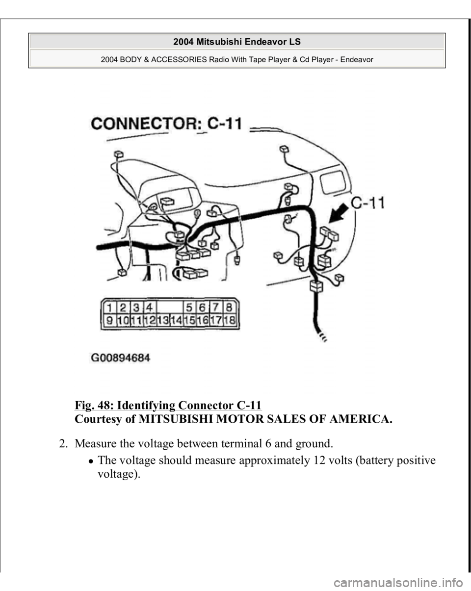
Fig. 48: Identifying Connector C
-11
Courtesy of MITSUBISHI MOTOR SALES OF AMERICA.
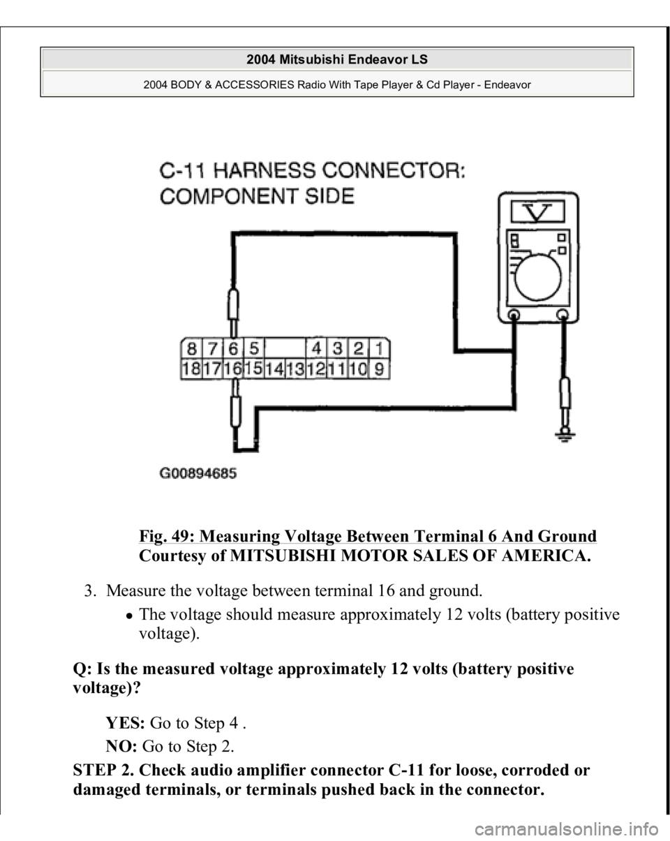
2. Measure the voltage between terminal 6 and ground.
The voltage should measure approximately 12 volts (battery positive
volta
ge).
2004 Mitsubishi Endeavor LS
2004 BODY & ACCESSORIES Radio With Tape Player & Cd Player - Endeavor
Page 1679 of 3870
Fig. 49: Measuring Voltage Between Terminal 6 And Ground
Courtesy of MITSUBISHI MOTOR SALES OF AMERICA.
3. Measure the voltage between terminal 16 and ground.
The voltage should measure approximately 12 volts (battery positive
voltage).
Q: Is the measured voltage approximately 12 volts (battery positive
voltage)?
YES: Go to Step 4 .
NO: Go to Step 2.
STEP 2. Check audio amplifier connector C-11 for loose, corroded or
damaged terminals, or terminals pushed back in the connector.
2004 Mitsubishi Endeavor LS
2004 BODY & ACCESSORIES Radio With Tape Player & Cd Player - Endeavor
Page 1680 of 3870
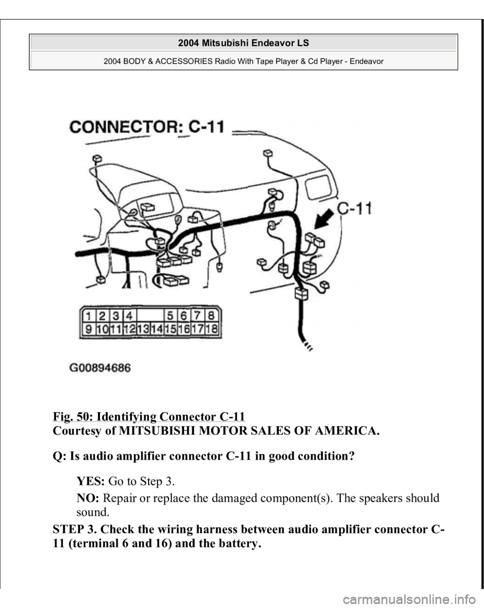
Fig. 50: Identifying Connector C
-11
Courtesy of MITSUBISHI MOTOR SALES OF AMERICA.
Q: Is audio amplifier connector C-11 in good condition?
YES: Go to Step 3.
NO: Repair or replace the damaged component(s). The speakers should
sound.
STEP 3. Check the wiring harness between audio amplifier connector C-
11 (terminal 6 and 16) and the battery.
2004 Mitsubishi Endeavor LS
2004 BODY & ACCESSORIES Radio With Tape Player & Cd Player - Endeavor
Trending: trailer, Transmission oil change, tightening bolts, horn, coolant capacity, Sensor, Anchor
