Rear suspension MITSUBISHI ENDEAVOR 2004 Service Repair Manual
[x] Cancel search | Manufacturer: MITSUBISHI, Model Year: 2004, Model line: ENDEAVOR, Model: MITSUBISHI ENDEAVOR 2004Pages: 3870, PDF Size: 98.47 MB
Page 252 of 3870
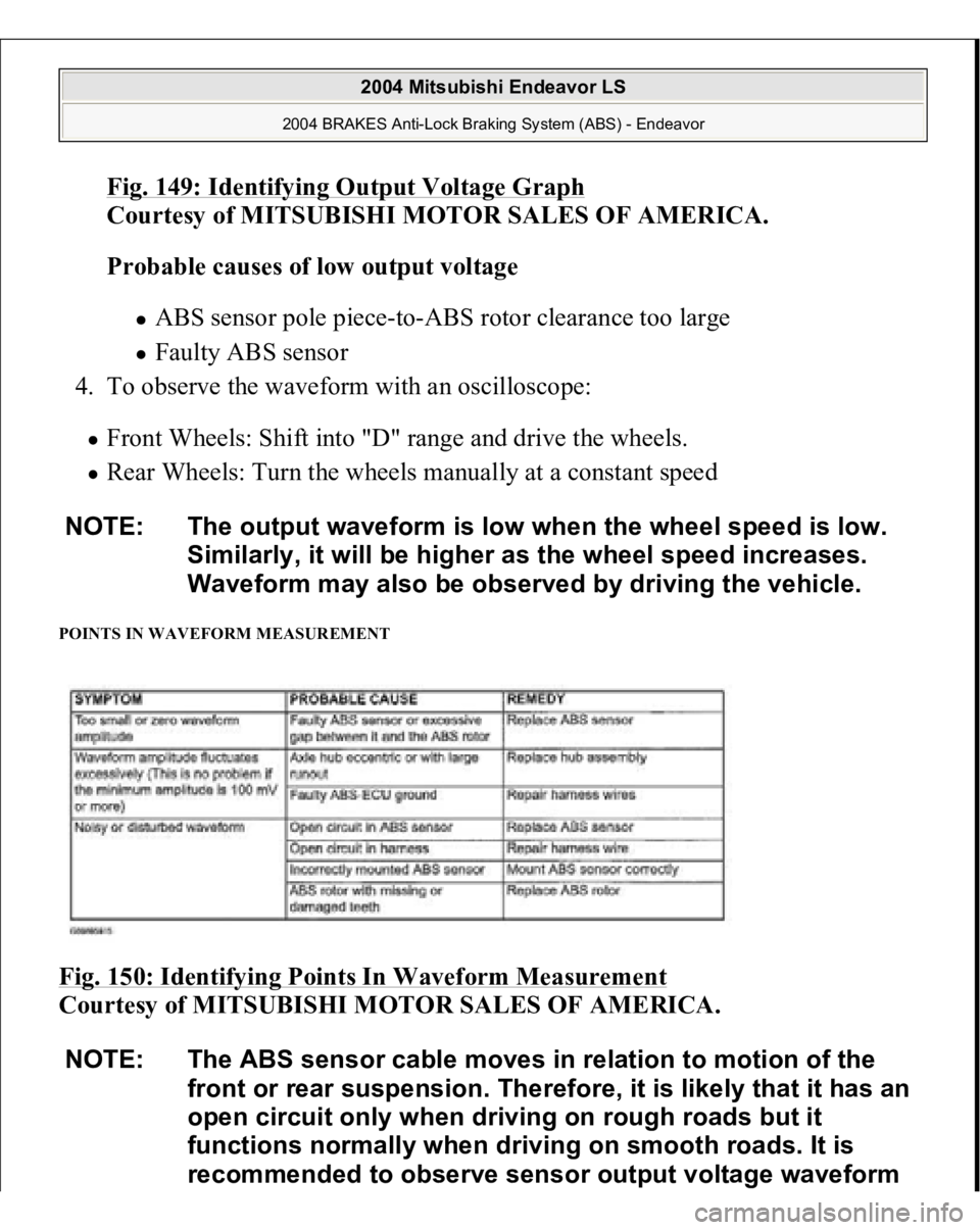
Fig. 149: Identifying Output Voltage Grap
h
Courtesy of MITSUBISHI MOTOR SALES OF AMERICA.
Probable causes of low output voltage
ABS sensor pole piece-to-ABS rotor clearance too large Faulty ABS sensor
4. To observe the waveform with an oscilloscope:
Front Wheels: Shift into "D" range and drive the wheels. Rear Wheels: Turn the wheels manually at a constant speed
POINTS IN WAVEFORM MEASUREMENT Fig. 150: Identifying Points In Waveform Measurement
Courtesy of MITSUBISHI MOTOR SALES OF AMERICA. NOTE: The output waveform is low when the wheel speed is low.
Similarly, it will be higher as the wheel speed increases.
Waveform may also be observed by driving the vehicle.
NOTE: The ABS sensor cable moves in relation to motion of the
front or rear suspension. Therefore, it is likely that it has an
open circuit only when driving on rough roads but it
functions normally when driving on smooth roads. It is
recommended to observe sensor output voltage waveform
2004 Mitsubishi Endeavor LS
2004 BRAKES Anti-Lock Braking System (ABS) - Endeavor
Page 1877 of 3870
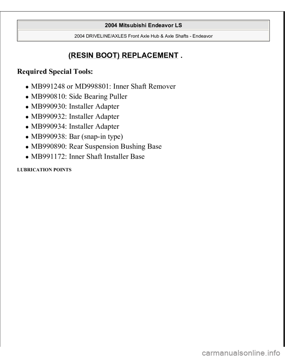
Required Special Tools:
MB991248 or MD998801: Inner Shaft Remover MB990810: Side Bearing Puller MB990930: Installer Adapter MB990932: Installer Adapter MB990934: Installer Adapter MB990938: Bar (snap-in type) MB990890: Rear Suspension Bushing Base MB991172: Inner Shaft Installer Base
LUBRICATION POINTS
(RESIN BOOT) REPLACEMENT
.
2004 Mitsubishi Endeavor LS
2004 DRIVELINE/AXLES Front Axle Hub & Axle Shafts - Endeavor
Page 1934 of 3870
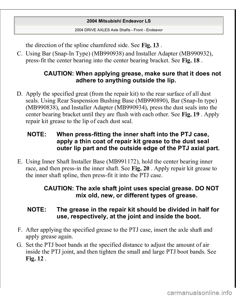
the direction of the spline chamfered side. See Fig. 13
.
C. Using Bar (Snap-In Type) (MB990938) and Installer Adapter (MB990932),
press-fit the center bearing into the center bearing bracket. See Fig. 18
.
D. Apply the specified great (from the repair kit) to the rear surface of all dust
seals. Using Rear Suspension Bushing Base (MB990890), Bar (Snap-In type)
(MB990838), and Installer Adapter (MB990934), press the dust seals into the
center bearing bracket until they are flush with each other. See Fig. 19 . Apply
repair kit grease to the lip of each dust seal.
E. Using Inner Shaft Installer Base (MB991172), hold the center bearing inner
race, and then press-in the inner shaft. See Fig. 20
. Apply repair kit grease to
the inner shaft spline, then press-fit it into the PTJ case.
F. After applying the specified grease to the PTJ case, insert the axle shaft and
apply grease again.
G. Set the PTJ boot bands at the specified distance to adjust the amount of air
inside the PTJ joint, and then tighten the small and large PTJ boot bands. See
Fi
g. 12
. CAUTION: When applying grease, make sure that it does not
adhere to anything outside the lip.
NOTE: When press-fitting the inner shaft into the PTJ case,
apply a thin coat of repair kit grease to the dust seal
outer lip part and the outside edge of the PTJ axial part.
CAUTION: The axle shaft joint uses special grease. DO NOT
mix old, new, or different types of grease.
NOTE: The grease in the repair kit should be divided in half for
use, respectively, at the joint and inside the boot.
2004 Mitsubishi Endeavor LS
2004 DRIVE AXLES Axle Shafts - Front - Endeavor
Page 1946 of 3870
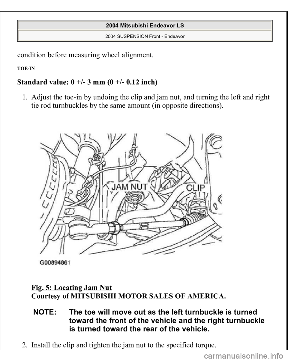
condition before measuring wheel alignment. TOE-IN Standard value: 0 +/- 3 mm (0 +/- 0.12 inch)
1. Adjust the toe-in by undoing the clip and jam nut, and turning the left and right
tie rod turnbuckles by the same amount (in opposite directions).
Fig. 5: Locating Jam Nut
Courtesy of MITSUBISHI MOTOR SALES OF AMERICA.
2. Install the cli
p and ti
ghten the
jam nut to the s
pecified tor
que.
NOTE: The toe will move out as the left turnbuckle is turned
toward the front of the vehicle and the right turnbuckle
is turned toward the rear of the vehicle.
2004 Mitsubishi Endeavor LS 2004 SUSPENSION Front - Endeavor
Page 1967 of 3870
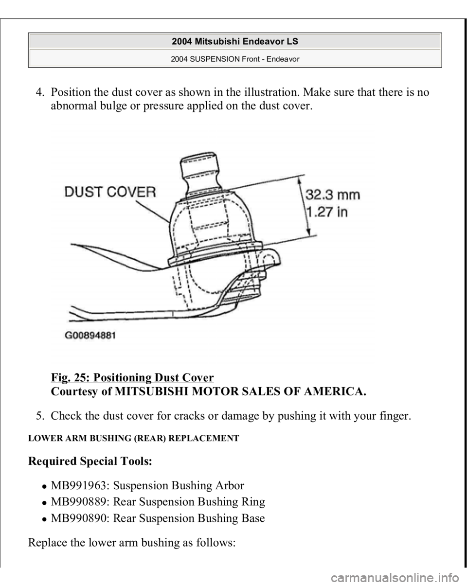
4. Position the dust cover as shown in the illustration. Make sure that there is no
abnormal bulge or pressure applied on the dust cover.
Fig. 25: Positioning Dust Cover
Courtesy of MITSUBISHI MOTOR SALES OF AMERICA.
5. Check the dust cover for cracks or damage by pushing it with your finger.
LOWER ARM BUSHING (REAR) REPLACEMENT Required Special Tools:
MB991963: Suspension Bushing Arbor MB990889: Rear Suspension Bushing Ring MB990890: Rear Suspension Bushing Base
Replace the lower arm bushin
g as follows:
2004 Mitsubishi Endeavor LS 2004 SUSPENSION Front - Endeavor
Page 1979 of 3870
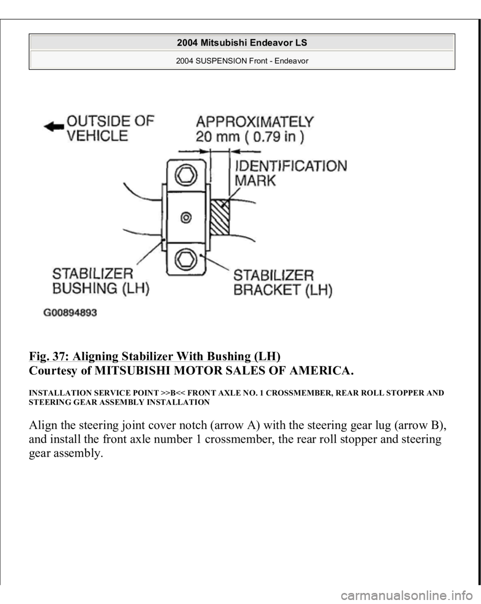
Fig. 37: Aligning Stabilizer With Bushing (LH)
Courtesy of MITSUBISHI MOTOR SALES OF AMERICA.
INSTALLATION SERVICE POINT >>B<< FRONT AXLE NO. 1 CROSSMEMBER, REAR ROLL STOPPER AND
STEERING GEAR ASSEMBLY INSTALLATION Align the steering joint cover notch (arrow A) with the steering gear lug (arrow B),
and install the front axle number 1 crossmember, the rear roll stopper and steering
gear assembly.
2004 Mitsubishi Endeavor LS 2004 SUSPENSION Front - Endeavor
Page 2925 of 3870
2004 SUSPENSION
Rear Axle < AWD > - Endeavor
GENERAL DESCRIPTION The rear axle has the following features.
The wheel bearing incorporates a unit ball bearing (double-row angular contact
ball bearing) for reduced friction. The rear wheel hub assembly combines the hub, wheel bearing, housing, and
oil seal in a single unit for fewer parts, better durability, improved assembly
precision, and better structural organization. The drive shaft has BJ-DOJ constant velocity joints. ABS rotor for wheel speed detection is press-fitted onto the drive shaft in
vehicles with ABS.
CONSTRUCTION DIAGRAM NOTE:
BJ: Birfield Joint DOJ: Double Offset Joint
2004 Mitsubishi Endeavor LS
2004 SUSPENSION Rear Axle < AWD > - Endeavor
2004 Mitsubishi Endeavor LS
2004 SUSPENSION Rear Axle < AWD > - Endeavor
Page 2926 of 3870
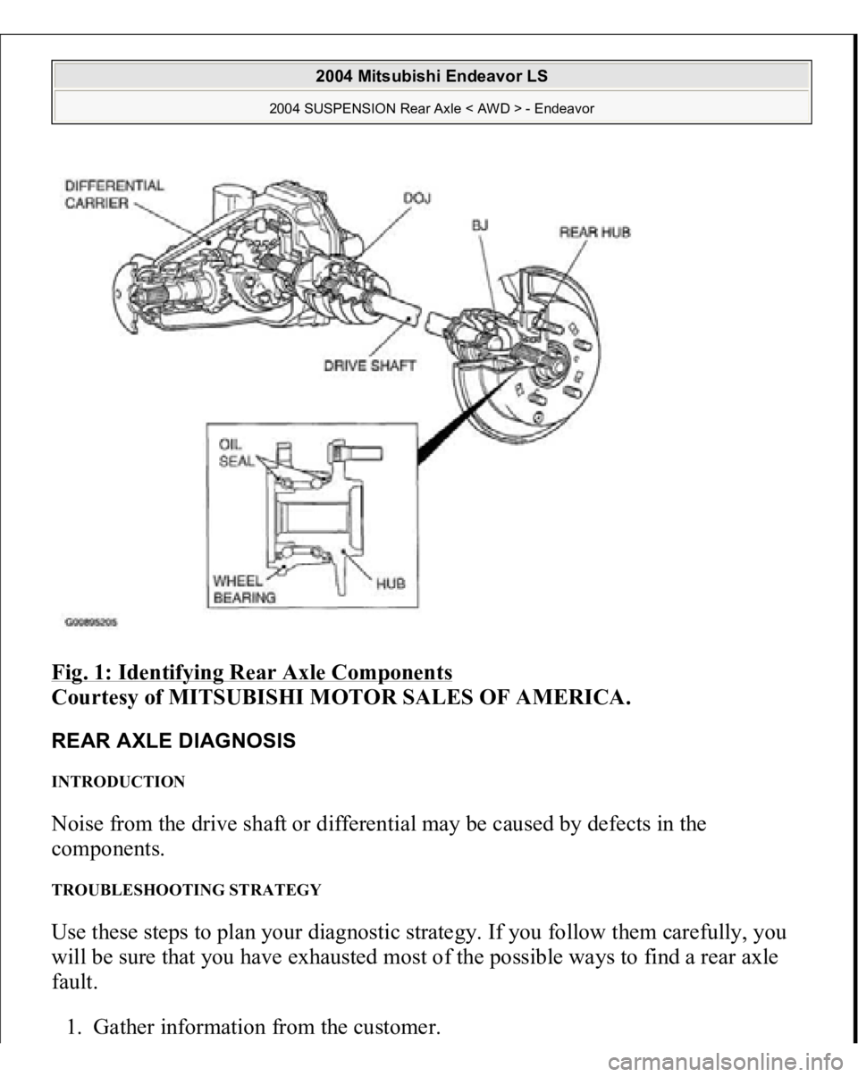
Fig. 1: Identifying Rear Axle Components
Courtesy of MITSUBISHI MOTOR SALES OF AMERICA.
REAR AXLE DIAGNOSIS INTRODUCTION Noise from the drive shaft or differential may be caused by defects in the
components. TROUBLESHOOTING STRATEGY Use these steps to plan your diagnostic strategy. If you follow them carefully, you
will be sure that you have exhausted most of the possible ways to find a rear axle
fault.
1. Gather information from the customer.
2004 Mitsubishi Endeavor LS
2004 SUSPENSION Rear Axle < AWD > - Endeavor
Page 2927 of 3870
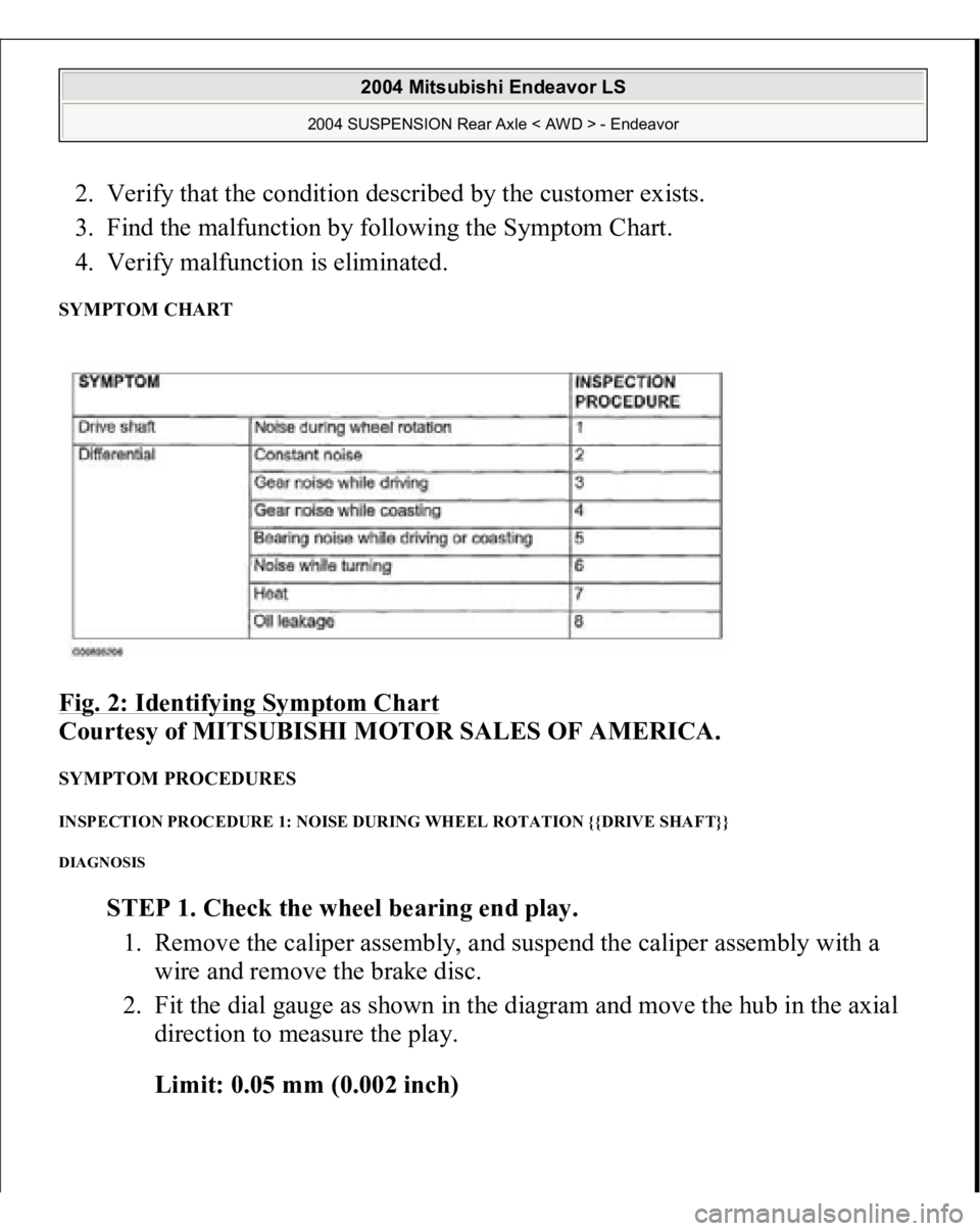
2. Verify that the condition described by the customer exists.
3. Find the malfunction by following the Symptom Chart.
4. Verify malfunction is eliminated. SYMPTOM CHART Fig. 2: Identifying Symptom Chart
Courtesy of MITSUBISHI MOTOR SALES OF AMERICA.
SYMPTOM PROCEDURES INSPECTION PROCEDURE 1: NOISE DURING WHEEL ROTATION {{DRIVE SHAFT}} DIAGNOSIS
STEP 1. Check the wheel bearing end play.
1. Remove the caliper assembly, and suspend the caliper assembly with a
wire and remove the brake disc.
2. Fit the dial gauge as shown in the diagram and move the hub in the axial
direction to measure the play.
Limit: 0.05 mm (0.002 inch)
2004 Mitsubishi Endeavor LS
2004 SUSPENSION Rear Axle < AWD > - Endeavor
Page 2928 of 3870
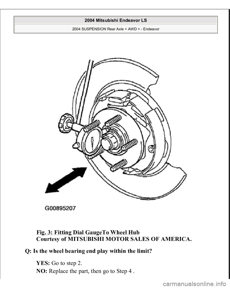
Fig. 3: Fitting Dial GaugeTo Wheel Hub
Courtesy of MITSUBISHI MOTOR SALES OF AMERICA.
Q: Is the wheel bearing end play within the limit?
YES: Go to step 2.
NO: Re
place the
part, then
go to Ste
p 4 .
2004 Mitsubishi Endeavor LS
2004 SUSPENSION Rear Axle < AWD > - Endeavor