fuel pressure MITSUBISHI ENDEAVOR 2004 Service Repair Manual
[x] Cancel search | Manufacturer: MITSUBISHI, Model Year: 2004, Model line: ENDEAVOR, Model: MITSUBISHI ENDEAVOR 2004Pages: 3870, PDF Size: 98.47 MB
Page 1096 of 3870
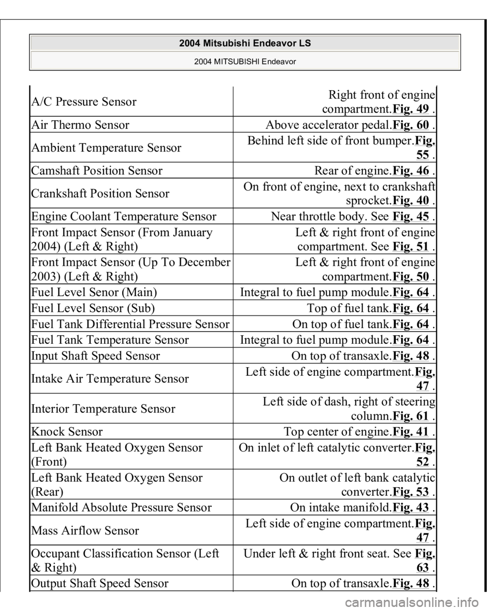
A/C Pressure Sensor
Right front of engine
compartment.Fig. 49
.
Air Thermo Sensor
Above accelerator pedal.Fig. 60
.
Ambient Temperature Sensor
Behind left side of front bumper.Fig.
55 .
Camshaft Position Sensor
Rear of engine.Fig. 46
.
Crankshaft Position Sensor
On front of engine, next to crankshaft
sprocket.Fig. 40
.
Engine Coolant Temperature Sensor
Near throttle body. See Fig. 45
.
Front Impact Sensor (From January
2004) (Left & Right)
Left & right front of engine
compartment. See Fig. 51
.
Front Impact Sensor (Up To December
2003) (Left & Right)
Left & right front of engine
compartment.Fig. 50
.
Fuel Level Senor (Main)
Integral to fuel pump module.Fig. 64
.
Fuel Level Sensor (Sub)
Top of fuel tank.Fig. 64
.
Fuel Tank Differential Pressure Sensor
On top of fuel tank.Fig. 64
.
Fuel Tank Temperature Sensor
Integral to fuel pump module.Fig. 64
.
Input Shaft Speed Sensor
On top of transaxle.Fig. 48
.
Intake Air Temperature Sensor
Left side of engine compartment.Fi
g.
47 .
Interior Temperature Sensor
Left side of dash, right of steering
column.Fig. 61
.
Knock Sensor
Top center of engine.Fig. 41
.
Left Bank Heated Oxygen Sensor
(Front)
On inlet of left catalytic converter.Fi
g.
52 .
Left Bank Heated Oxygen Sensor
(Rear)
On outlet of left bank catalytic
converter.Fig. 53
.
Manifold Absolute Pressure Sensor
On intake manifold.Fig. 43
.
Mass Airflow Sensor
Left side of engine compartment.Fi
g.
47 .
Occupant Classification Sensor (Left
& Right)
Under left & right front seat. See Fi
g.
63 .
Output Shaft Speed Sensor
On top of transaxle.Fig. 48
.
2004 Mitsubishi Endeavor LS
2004 MITSUBISHI Endeavor
Page 1097 of 3870
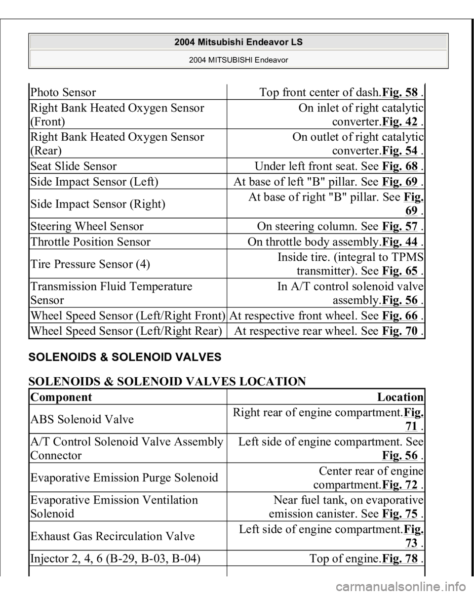
SOLENOIDS & SOLENOID VALVES SOLENOIDS & SOLENOID VALVES LOCATION Photo Sensor
Top front center of dash.Fig. 58
.
Right Bank Heated Oxygen Sensor
(Front)
On inlet of right catalytic
converter.Fig. 42
.
Right Bank Heated Oxygen Sensor
(Rear)
On outlet of right catalytic
converter.Fig. 54
.
Seat Slide Sensor
Under left front seat. See Fig. 68
.
Side Impact Sensor (Left)
At base of left "B" pillar. See Fig. 69
.
Side Impact Sensor (Right)
At base of right "B" pillar. See Fig.
69 .
Steering Wheel Sensor
On steering column. See Fig. 57
.
Throttle Position Sensor
On throttle body assembly.Fig. 44
.
Tire Pressure Sensor (4)
Inside tire. (integral to TPMS
transmitter). See Fig. 65
.
Transmission Fluid Temperature
Sensor
In A/T control solenoid valve
assembly.Fig. 56
.
Wheel Speed Sensor (Left/Right Front)
At respective front wheel. See Fig. 66
.
Wheel Speed Sensor (Left/Right Rear)
At respective rear wheel. See Fig. 70
.
Component
Location
ABS Solenoid Valve
Right rear of engine compartment.Fig.
71 .
A/T Control Solenoid Valve Assembly
Connector
Left side of engine compartment. See
Fig. 56
.
Evaporative Emission Purge Solenoid
Center rear of engine
compartment.Fig. 72
.
Evaporative Emission Ventilation
Solenoid
Near fuel tank, on evaporative
emission canister. See Fig. 75
.
Exhaust Gas Recirculation Valve
Left side of engine compartment.Fig.
73 .
Injector 2, 4, 6 (B-29, B-03, B-04)
Top of engine.Fig. 78
.
2004 Mitsubishi Endeavor LS
2004 MITSUBISHI Endeavor
Page 1365 of 3870
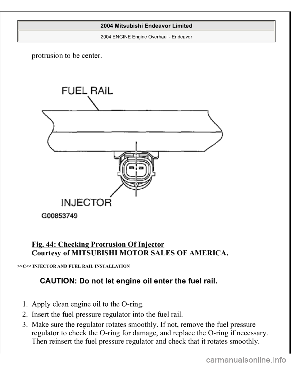
protrusion to be center.
Fig. 44: Checking Protrusion Of Injector
Courtesy of MITSUBISHI MOTOR SALES OF AMERICA.
>>C<< INJECTOR AND FUEL RAIL INSTALLATION 1. Apply clean engine oil to the O-ring.
2. Insert the fuel pressure regulator into the fuel rail.
3. Make sure the regulator rotates smoothly. If not, remove the fuel pressure
regulator to check the O-ring for damage, and replace the O-ring if necessary.
Then reinsert the fuel pressure regulator and chec
k that it rotates smoothly.
CAUTION: Do not let engine oil enter the fuel rail.
2004 Mitsubishi Endeavor Limited 2004 ENGINE Engine Overhaul - Endeavor
Page 1387 of 3870
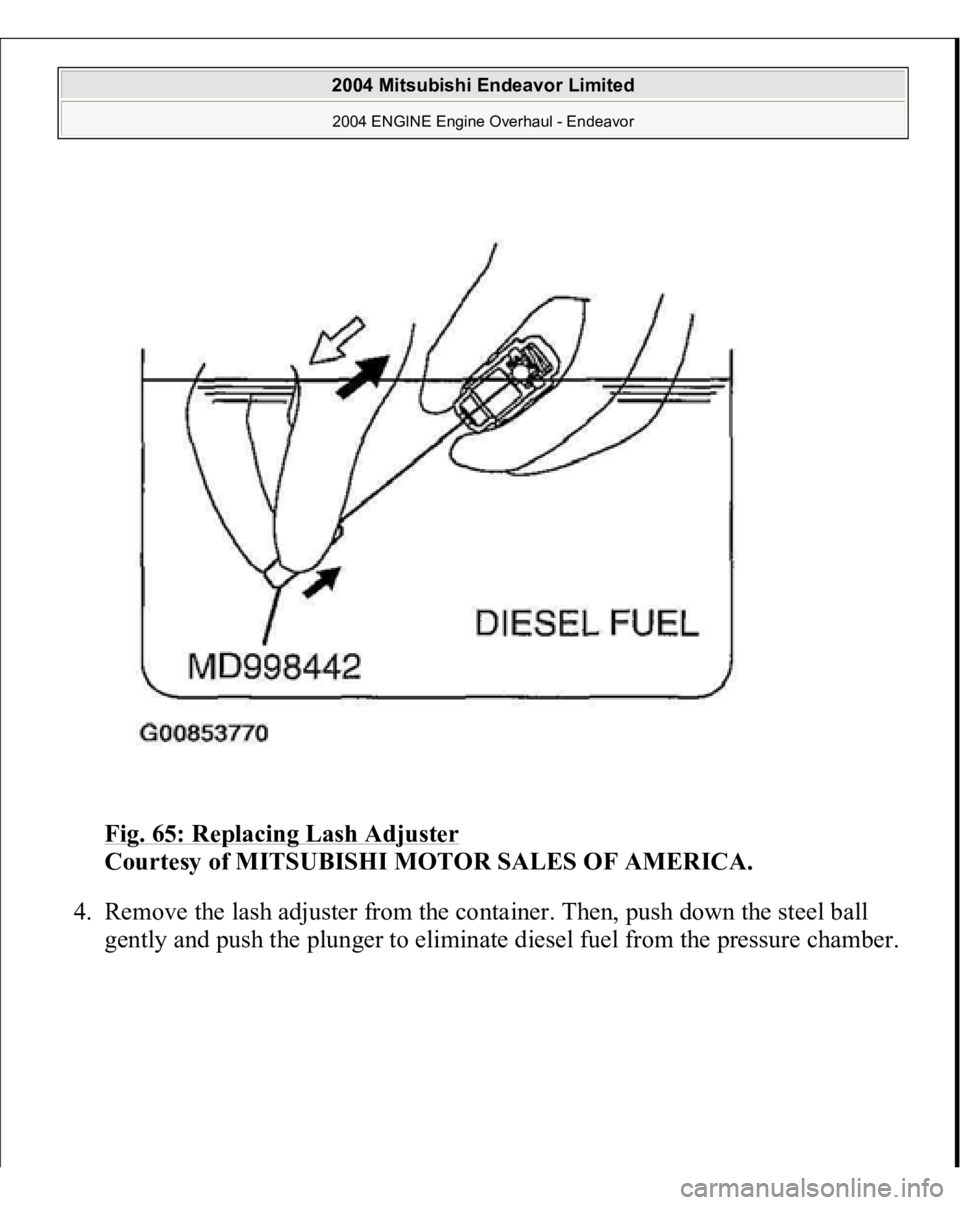
Fig. 65: Replacing Lash Adjuster
Courtesy of MITSUBISHI MOTOR SALES OF AMERICA.
4. Remove the lash adjuster from the container. Then, push down the steel ball
gentl
y and
push the
plun
ger to eliminate diesel fuel from the
pressure chamber.
2004 Mitsubishi Endeavor Limited 2004 ENGINE Engine Overhaul - Endeavor
Page 1388 of 3870
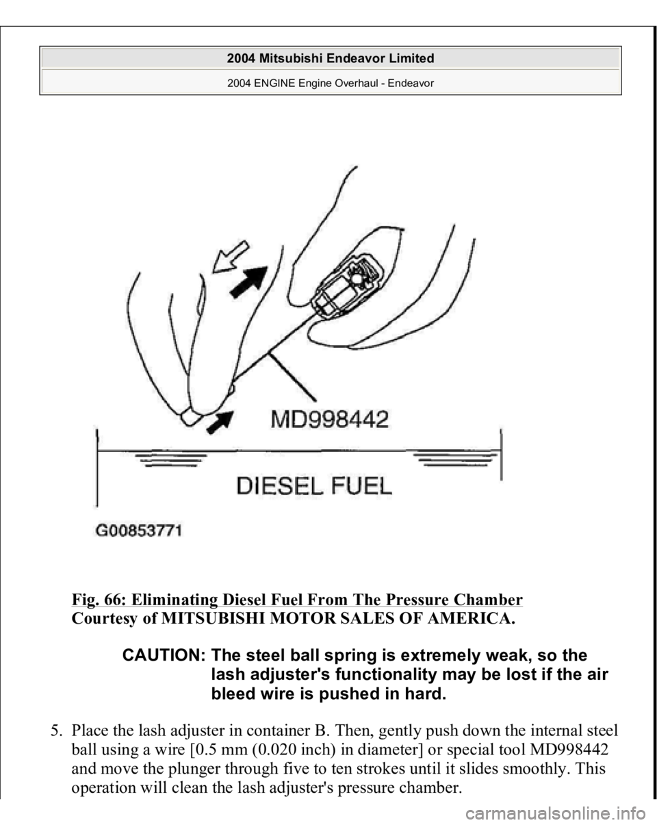
Fig. 66: Eliminating Diesel Fuel From The Pressure Chamber
Courtesy of MITSUBISHI MOTOR SALES OF AMERICA.
5. Place the lash adjuster in container B. Then, gently push down the internal steel
ball using a wire [0.5 mm (0.020 inch) in diameter] or special tool MD998442
and move the plunger through five to ten strokes until it slides smoothly. This
o
peration will clean the lash ad
juster's
pressure chamber.
CAUTION: The steel ball spring is extremely weak, so the
lash adjuster's functionality may be lost if the air
bleed wire is pushed in hard.
2004 Mitsubishi Endeavor Limited 2004 ENGINE Engine Overhaul - Endeavor
Page 1389 of 3870
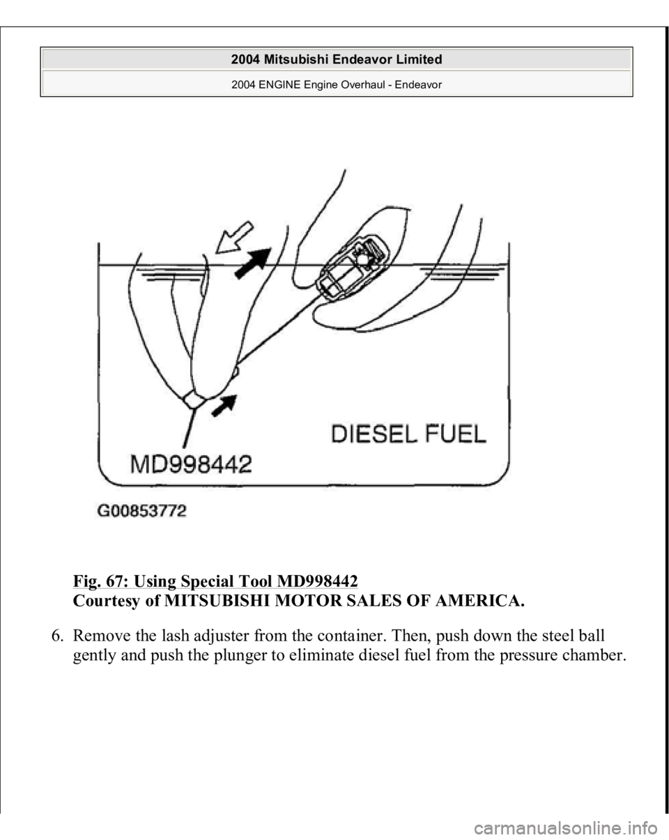
Fig. 67: Using Special Tool MD998442
Courtesy of MITSUBISHI MOTOR SALES OF AMERICA.
6. Remove the lash adjuster from the container. Then, push down the steel ball
gentl
y and
push the
plun
ger to eliminate diesel fuel from the
pressure chamber.
2004 Mitsubishi Endeavor Limited 2004 ENGINE Engine Overhaul - Endeavor
Page 1390 of 3870
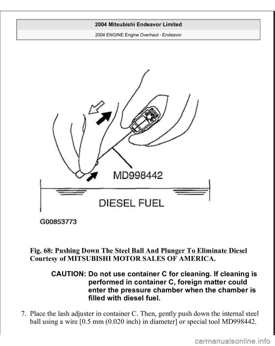
Fig. 68: Pushing Down The Steel Ball And Plunger To Eliminate Diesel
Courtesy of MITSUBISHI MOTOR SALES OF AMERICA.
7. Place the lash adjuster in container C. Then, gently push down the internal steel
ball using a wire [0.5 mm (0.020 inch) in diameter] or special tool MD998442.
CAUTION: Do not use container C for cleanin
g. If cleanin
g is
performed in container C, foreign matter could
enter the pressure chamber when the chamber is
filled with diesel fuel.
2004 Mitsubishi Endeavor Limited 2004 ENGINE Engine Overhaul - Endeavor
Page 1391 of 3870
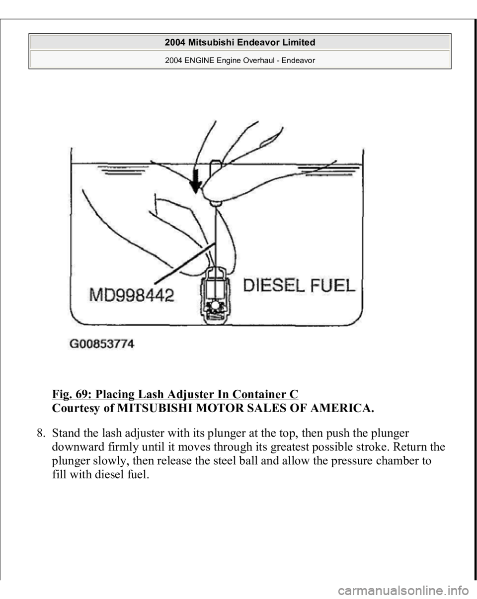
Fig. 69: Placing Lash Adjuster In Container C
Courtesy of MITSUBISHI MOTOR SALES OF AMERICA.
8. Stand the lash adjuster with its plunger at the top, then push the plunger
downward firmly until it moves through its greatest possible stroke. Return the
plunger slowly, then release the steel ball and allow the pressure chamber to
fill with diesel fuel.
2004 Mitsubishi Endeavor Limited 2004 ENGINE Engine Overhaul - Endeavor
Page 1524 of 3870
Mixture Check)
Courtesy of MITSUBISHI MOTOR SALES OF AMERICA.
3. Check that the basic ignition timing is within the standard value.
Standard value: 5° BTDC+/-3°
4. Start the engine and increase the engine speed to 2,500 r/min for 2 minutes.
5. Set the CO, HC tester.
6. Check the CO contents and the HC contents at idle.
Standard value:
CO contents: 0.5% or less
HC contents: 100 ppm or less
7. If the CO and HC contents do not remain inside the standard value, check the
following items:
Diagnostic output Closed-loop control (When the closed-loop control is carried out normally, the
output signal of the heated oxygen sensor changes between 0 - 400 mV and
600 - 1,000 mV at idle.) Fuel pressures Injector Ignition coil, spark plug EGR system and EGR valve leak Evaporative emission system Compression pressure
COMPRESSION PRESSURE CHECK Re
quired S
pecial Tool
:
NOTE: Replace the catalytic converter when the CO and HC
contents do not remain inside the standard value, even
though the result of the inspection is normal for all items.
2004 Mitsubishi Endeavor Limited
2004 ENGINE Engine - Endeavor
Page 1539 of 3870
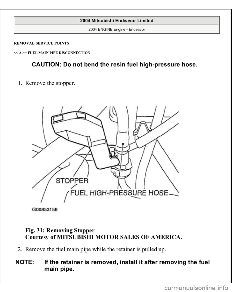
REMOVAL SERVICE POINTS << A >> FUEL MAIN PIPE DISCONNECTION 1. Remove the stopper.
Fig. 31: Removing Stopper
Courtesy of MITSUBISHI MOTOR SALES OF AMERICA.
2. Remove the fuel main pipe while the retainer is pulled up.
CAUTION: Do not bend the resin fuel high-pressure hose.
NOTE: If the retainer is removed, install it after removing the fuel
main pipe.
2004 Mitsubishi Endeavor Limited
2004 ENGINE Engine - Endeavor