turn signal MITSUBISHI ENDEAVOR 2004 Service Repair Manual
[x] Cancel search | Manufacturer: MITSUBISHI, Model Year: 2004, Model line: ENDEAVOR, Model: MITSUBISHI ENDEAVOR 2004Pages: 3870, PDF Size: 98.47 MB
Page 28 of 3870
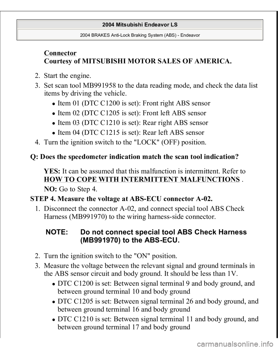
Connector
Courtesy of MITSUBISHI MOTOR SALES OF AMERICA.
2. Start the engine.
3. Set scan tool MB991958 to the data reading mode, and check the data list
items by driving the vehicle.
Item 01 (DTC C1200 is set): Front right ABS sensor Item 02 (DTC C1205 is set): Front left ABS sensor Item 03 (DTC C1210 is set): Rear right ABS sensor Item 04 (DTC C1215 is set): Rear left ABS sensor
4. Turn the ignition switch to the "LOCK" (OFF) position.
Q: Does the speedometer indication match the scan tool indication?
YES: It can be assumed that this malfunction is intermittent. Refer to
HOW TO COPE WITH INTERMITTENT MALFUNCTIONS
.
NO: Go to Step 4.
STEP 4. Measure the voltage at ABS-ECU connector A-02.
1. Disconnect the connector A-02, and connect special tool ABS Check
Harness (MB991970) to the wiring harness-side connector.
2. Turn the ignition switch to the "ON" position.
3. Measure the voltage between the relevant signal and ground terminals in
the ABS sensor circuit and body ground. It should be less than 1V.
DTC C1200 is set: Between signal terminal 9 and body ground, and
between ground terminal 10 and body ground DTC C1205 is set: Between signal terminal 26 and body ground, and
between ground terminal 16 and body ground DTC C1210 is set: Between signal terminal 11 and body ground, and between
ground terminal 17 and bod
y ground NOTE: Do not connect special tool ABS Check Harness
(MB991970) to the ABS-ECU.
2004 Mitsubishi Endeavor LS
2004 BRAKES Anti-Lock Braking System (ABS) - Endeavor
Page 57 of 3870
Courtesy of MITSUBISHI MOTOR SALES OF AMERICA
.
6. Turn the ignition switch to the "LOCK" (OFF) position.
Q: Is DTC C1200, C1205, C1210 or C1215 set?
YES: Repeat the troubleshooting from Step 1 .
NO: The procedure is complete.
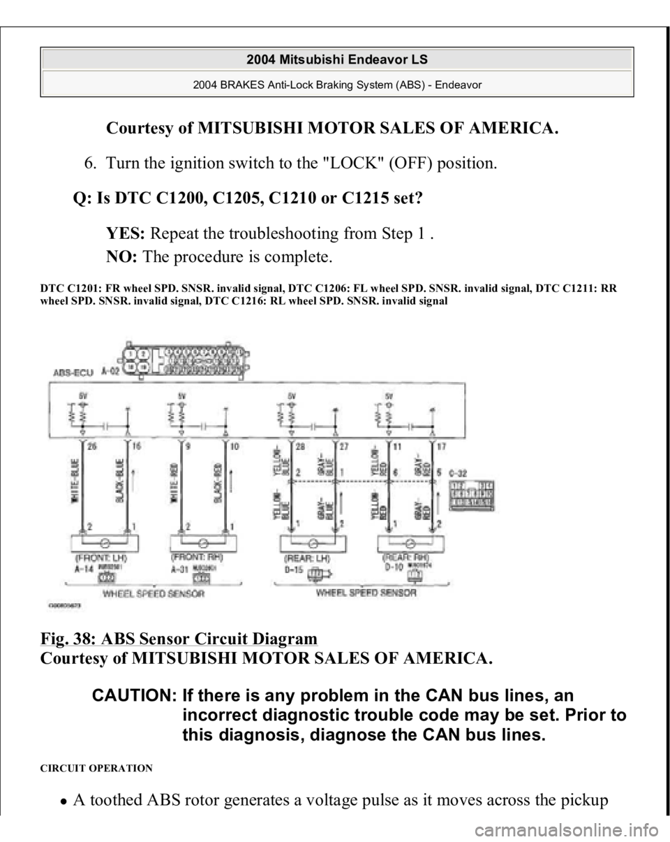
DTC C1201: FR wheel SPD. SNSR. invalid signal, DTC C1206: FL wheel SPD. SNSR. invalid signal, DTC C1211: RR
wheel SPD. SNSR. invalid signal, DTC C1216: RL wheel SPD. SNSR. invalid signal Fig. 38: ABS Sensor Circuit Diagram
Courtesy of MITSUBISHI MOTOR SALES OF AMERICA.
CIRCUIT OPERATION
A toothed ABS rotor
generates a volta
ge pulse as i
t moves across the
picku
p
CAUTION: If there is any problem in the CAN bus lines, an
incorrect diagnostic trouble code may be set. Prior to
this diagnosis, diagnose the CAN bus lines.
2004 Mitsubishi Endeavor LS
2004 BRAKES Anti-Lock Braking System (ABS) - Endeavor
Page 69 of 3870
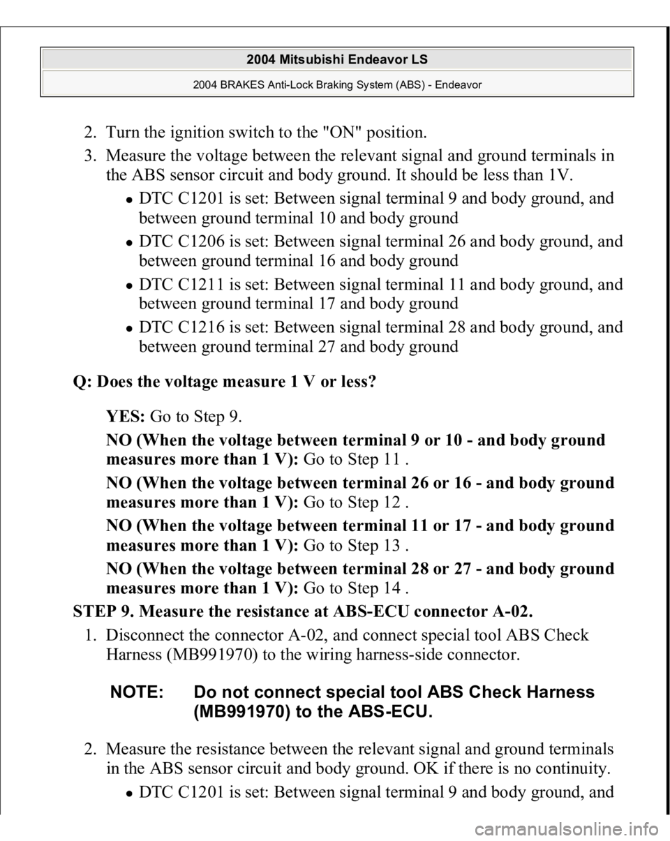
2. Turn the ignition switch to the "ON" position.
3. Measure the voltage between the relevant signal and ground terminals in
the ABS sensor circuit and body ground. It should be less than 1V.
DTC C1201 is set: Between signal terminal 9 and body ground, and
between ground terminal 10 and body ground DTC C1206 is set: Between signal terminal 26 and body ground, and
between ground terminal 16 and body ground DTC C1211 is set: Between signal terminal 11 and body ground, and
between ground terminal 17 and body ground DTC C1216 is set: Between signal terminal 28 and body ground, and
between ground terminal 27 and body ground
Q: Does the voltage measure 1 V or less?
YES: Go to Step 9.
NO (When the voltage between terminal 9 or 10 - and body ground
measures more than 1 V): Go to Step 11 .
NO (When the voltage between terminal 26 or 16 - and body ground
measures more than 1 V): Go to Step 12 .
NO (When the voltage between terminal 11 or 17 - and body ground
measures more than 1 V): Go to Step 13 .
NO (When the voltage between terminal 28 or 27 - and body ground
measures more than 1 V): Go to Step 14 .
STEP 9. Measure the resistance at ABS-ECU connector A-02.
1. Disconnect the connector A-02, and connect special tool ABS Check
Harness (MB991970) to the wiring harness-side connector.
2. Measure the resistance between the relevant signal and ground terminals
in the ABS sensor circuit and body ground. OK if there is no continuity. DTC C1201 is set: Between signal terminal 9 and bo
dy ground, and NOTE: Do not connect special tool ABS Check Harness
(MB991970) to the ABS-ECU.
2004 Mitsubishi Endeavor LS
2004 BRAKES Anti-Lock Braking System (ABS) - Endeavor
Page 243 of 3870
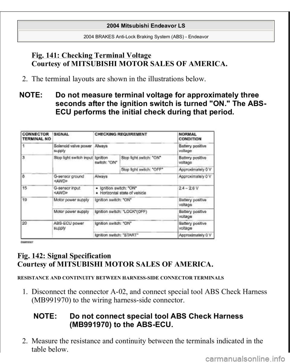
Fig. 141: Checking Terminal Voltage
Courtesy of MITSUBISHI MOTOR SALES OF AMERICA.
2. The terminal layouts are shown in the illustrations below.
Fig. 142: Signal Specification
Courtesy of MITSUBISHI MOTOR SALES OF AMERICA.
RESISTANCE AND CONTINUITY BETWEEN HARNESS-SIDE CONNECTOR TERMINALS 1. Disconnect the connector A-02, and connect special tool ABS Check Harness
(MB991970) to the wiring harness-side connector.
2. Measure the resistance and continuity between the terminals indicated in the
table below. NOTE: Do not measure terminal voltage for approximately three
seconds after the ignition switch is turned "ON." The ABS-
ECU performs the initial check during that period.
NOTE: Do not connect special tool ABS Check Harness
(MB991970) to the ABS-ECU.
2004 Mitsubishi Endeavor LS
2004 BRAKES Anti-Lock Braking System (ABS) - Endeavor
Page 807 of 3870
Fig. 12: Identifying Power Plant ECU Check Harness (MB991923)
Courtesy of MITSUBISHI MOTOR SALES OF AMERICA.
TEST B: RADIATOR FAN & CONDENSER FAN DO NOT CHANGE SPEED OR STOP Technical Description The fan control module has variable control of the radiator fan motor and the
condenser fan motor speeds using signals transmitted from the PCM. Troubleshooting Hints
Malfunction of fan control relay. Malfunction of fan control module. Malfunction of PCM.
Diagnosis 1. Check the fan control relay. See FAN CONTROL RELAY
under
COMPONENT TESTS. If fan control relay is okay, go to next step. If fan
control module is damaged, repair or replace as necessary and retest.
2. Check the harness wire between terminal No. 2 of fan control relay connector
A-10X and terminal No. 3 of fan control module connector A-18. See Fig. 7
and Fig. 8
. If wiring is damaged, repair or replace as necessary and retest. If
wiring is okay, go to next step.
3. Disconnect all the connectors from the PCM. Connect Power Plant ECU Check
Harness (MB991923
) between the PCM and the bod
y-side harness connector.
NOTE: If the engine coolant temperature reaches 230°F (110°C) or
higher, the radiator fan control runs the radiator fan for up
to 5 minutes even after the ignition switch is turned to the
LOCK position. The fan stops its rotation when the engine
coolant temperature decreases to 230°F (110°C) or l ower.
NOTE: Measure the output circuit voltage at terminal No. 10 of
PCM connector B-18 by using Power Plant ECU Check
Harness (MB991923). See Fig. 11
and Fig. 12
.
2004 Mitsubishi Endeavor Limited
2004 ENGINE COOLING Electric Cooling Fans - Endeavor
Page 879 of 3870
Courtesy of MITSUBISHI MOTOR SALES OF AMERICA
.
2. Turn the ignition switch to the "ON" position.
3. Set scan tool MB991958 to read the diagnostic trouble codes.
4. Turn the ignition switch to the "LOCK" (OFF) position.
5. Disconnect scan tool MB991958.
Q: Is DTC 15 set?
YES : Return to Step 1 .
NO : The procedure is complete.
DTC 21: Cancel Latch Signal System DTC SET CONDITIONS The PCM communicates cancellation retention information between the two
microprocessors. This DTC is set when cancellation retention information contains
inconsistency. TROUBLESHOOTING HINTS (The most likely causes for this code to be set are:) Malfunction of the PCM. DIAGNOSIS Replace the PCM. [Refer to POWERTRAIN CONTROL MODULE (PCM)
].
Check that diagnostic trouble code 21 is not set.
DTC 22: Stoplight Switch System
2004 Mitsubishi Endeavor LS
2004 BODY & ACCESSORIES Auto, Cruise Control System - Endeavor
Page 965 of 3870
Courtesy of MITSUBISHI MOTOR SALES OF AMERICA
.
CIRCUIT OPERATION The PCM detects "CRUISE" (MAIN) switch "ON" signal to illuminate the
"CRUISE" indicator light on the combination meter. COMMENT Connector(s), wiring harness in the CAN bus line between the PCM and the
combination meter, power supply to the PCM, the combination meter, the PCM
may be defective. TROUBLESHOOTING HINTS
Malfunction of the combination meter Damaged harness, connector Malfunction of the PCM
DIAGNOSIS REQUIRED SPECIAL TOOL:
MB991958: Scan Tool (MUT-III Sub Assembly)
MB991824: V.C.I. MB991827: USB Cable MB991910: Main Harness A
STEP 1. Using scan tool MB991958, diagnose the CAN bus line.
Use scan tool MB991958 to diagnose the CAN bus lines.
1. Connect scan tool MB991958 to the data link connec
tor.
(Refer to AUTO
-
CAUTION: To prevent damage to scan tool MB991958,
always turn the ignition switch to the
"LOCK" (OFF) position before connecting or
disconnecting scan tool MB991958.
2004 Mitsubishi Endeavor LS
2004 BODY & ACCESSORIES Auto, Cruise Control System - Endeavor
Page 1017 of 3870
Fig. 13: Identifying Run Channel, Lower Sash And Door Sas
h
Courtesy of MITSUBISHI MOTOR SALES OF AMERICA.
5. If repair or adjustment is not possible, replace the door assembly.
POWER WINDOW TIMER FUNCTION CHECK After the doors are closed and the ignition switch is turned to the "LOCK" (OFF)
position, the power windows should work within 30 seconds. The timer expires if
the front door is opened during that 30 second time. If it does not, carry out the
timer troubleshooting in SYMPTOM CHART
.
POWER WINDOW OPERATING CURRENT CHECK 1. Remove the power window fuse and connect an ammeter as shown in the
illustration.
2. When the power window switch is pressed in the "UP" position, a large amoun
t
of current flows from the time the window starts to close until it is fully closed,
Measure the current during this time
Standard value (A): 5 +/-1A [Power supply voltage 14.5 +/-0.5V, 25°C (77°
F)]
3. If the operation current is outside the standard value, refer to INPUT SIGNAL
CHART
.
2004 Mitsubishi Endeavor LS
2004 BODY & ACCESSORIES Door - Endeavor
Page 1220 of 3870
Courtesy of MITSUBISHI MOTOR SALES OF AMERICA
.
STEP 14. Check the symptoms.
Q: Do the radiator fan and condenser fan operate correctly?
YES: The procedure is complete.
NO: Return to Step 1 .
INSPECTION PROCEDURE 4: Radiator Fan and Condenser Fan do not Change Speed or Stop Radiator Fan and Condenser Fan Drive Circuit Refer to INSPECTION PROCEDURE 3: RADIATOR FAN AND CONDENSER FAN DO NOT OPERATE
.
CIRCUIT OPERATION
The fan control module is powered from fusible link number 2. The PCM judges the required revolution speed of radiator fan motor and
condenser fan motor using the input signals transmitted from A/C switch,
automatic compressor controller, vehicle speed sensor and engine coolant
temperature sensor. The PCM activates the fan control module to drive the
radiator fan motor and condenser fan motor.
TECHNICAL DESCRIPTION The fan controller has variable control of the radiator fan motor and the condenser
fan motor speeds using signals transmitted from the PCM. TROUBLESHOOTING HINTS NOTE: If the engine coolant temperature reaches 110°C (230°F) or
higher, the radiator fan control runs the radiator fan for up
to 5 minutes even after the ignition switch is turned to the
"LOCK" (OFF) position [the fan stops its rotation when the
engine coolant temperature decreases to 110°C (230° F) or
lower.]
2004 Mitsubishi Endeavor Limited 2004 ENGINE Engine Cooling - Endeavor
Page 1235 of 3870
NO: Replace the radiator fan motor. Then go to Step 7.
STEP 7. Check the symptoms.
Q: Do the radiator fan and condenser fan operate correctly?
YES: The procedure is complete.
NO: Return to Step 1 .
INSPECTION PROCEDURE 5: Radiator Fan does not Operate TECHNICAL DESCRIPTION The cause could be a malfunction of the radiator fan motor or an open circuit
between the fan control module and the radiator fan motor. TROUBLESHOOTING HINTS Malfunction of radiator fan motor DIAGNOSIS Replace the radiator fan motor. INSPECTION PROCEDURE 6: Condenser Fan does not Operate Radiator Fan and Condenser Fan Drive Circuit Refer to INSPECTION PROCEDURE 3: RADIATOR FAN AND CONDENSER FAN DO NOT OPERATE
.
CIRCUIT OPERATION
The fan control module is powered from fusible link number 2. The PCM judges the required revolution speed of radiator fan motor and
condenser fan motor using the input signals transmitted from A/C switch,
automatic compressor controller, vehicle speed sensor and engine coolant
temperature sensor. The PCM activates the fan control module to drive the
radiator fan motor and condenser fan motor.
TECHNICAL DESCRIPTION
2004 Mitsubishi Endeavor Limited 2004 ENGINE Engine Cooling - Endeavor