brake light MITSUBISHI ENDEAVOR 2004 Service Repair Manual
[x] Cancel search | Manufacturer: MITSUBISHI, Model Year: 2004, Model line: ENDEAVOR, Model: MITSUBISHI ENDEAVOR 2004Pages: 3870, PDF Size: 98.47 MB
Page 4 of 3870
LONG STOPPING DISTANCES ON LOOSE ROAD SURFACESWhen braking on loose surfaces like snow-covered or gravel roads, the stopping
distance can be longer for an ABS-equipped vehicle than the stopping distance for a
vehicle with a conventional brake system. SHOCK AT STARTING CHECK Shock may be felt when the brake pedal is lightly pressed while driving at a low
speed. This is a normal characteristic because the ABS system operation check is
carried out when vehicle speed is 8 km/h (5 mph) or less. ANTI-LOCK BRAKING SYSTEM (ABS) DIAGNOSIS INTRODUCTION TO ANTI-LOCK BRAKING SYSTEM DIAGNOSIS The anti-lock braking system (ABS) operates differently from conventional brake
systems. These differences include sounds, sensations, and vehicle performance that
owners and service technicians who are not familiar with ABS may not be used to.
Some operational characteristics may seem to be malfunctions, but they are simply
signs of normal ABS operation. When diagnosing the ABS system, keep these
operational characteristics in mind. Inform the owner of the kind of performance
characteristics to expect from an ABS-equipped vehicle. ABS DIAGNOSTIC TROUBLE CODE DETECTION CONDITIONS ABS diagnostic trouble codes (ABS DTCs) are set under different conditions,
depending on the malfunction detected. Most ABS DTCs will only be set during
vehicle operation. Some ABS DTCs will also be set during the ABS self-check
immediately after the engine is started.
When you check if an ABS DTC will be displayed again after the DTC has been
erased, you should duplicate the ABS DTC set conditions. Depending on the
detection timing and set conditions for the specific ABS DTC, you must either drive
the vehicle or turn the engine off and restart it. To set the proper conditions for that
DTC again, refer to ABS DTC SET CONDITIONS
for each ABS DTC that you
are trying to reset.
ABS DIAGNOSTIC TROUBLESHOOTING STRATEGY
2004 Mitsubishi Endeavor LS
2004 BRAKES Anti-Lock Braking System (ABS) - Endeavor
Page 8 of 3870
Courtesy of MITSUBISHI MOTOR SALES OF AMERICA
.
4. Connect special tool MB991910 to the V.C.I.
5. Connect special tool to the data link connector.
6. Turn the V.C.I. power switch to the "ON" position.
7. Start the MUT-III system on the personal computer.
HOW TO READ AND ERASE DIAGNOSTIC TROUBLE CODES Required Special Tools:
MB991958: Scan Tool (MUT-III Sub Assembly)
MB991824: Vehicle Communication Interface (V.C.I.) MB991827: MUT-III USB Cable MB991910: MUT-III Main Harness A
1. Connect scan tool MB991958 to the data link connec
tor. NOTE: When the V.C.I. is energized, the V.C.I. indicator light
will be illuminated in a green color.
NOTE: Disconnect the scan tool in the reverse order of the
connecting sequence, making sure that the ignition
switch is at the "LOCK" (OFF) position.
CAUTION: To prevent damage to scan tool MB991958, always
turn the ignition switch to the "LOCK" (OFF) position
before connecting or disconnecting scan tool
MB991958.
NOTE: If the battery voltage is low, diagnostic trouble codes will
not be set. Check the battery if scan tool MB991958 does
not display.
2004 Mitsubishi Endeavor LS
2004 BRAKES Anti-Lock Braking System (ABS) - Endeavor
Page 230 of 3870
YES: The procedure is complete.
NO: Go to Step 1 .
INSPECTION PROCEDURE 3: WHEN THE IGNITION KEY IS TURNED TO ON (ENGINE STOPPED), THE
BRAKE/ABS WARNING LIGHT DOES NOT ILLUMINATE, INSPECTION PROCEDURE 4: THE BRAKE/ABS
WARNING LIGHT REMAINS ILLUMINATED AFTER THE ENGINE IS STARTED
2004 Mitsubishi Endeavor LS
2004 BRAKES Anti-Lock Braking System (ABS) - Endeavor
Page 232 of 3870
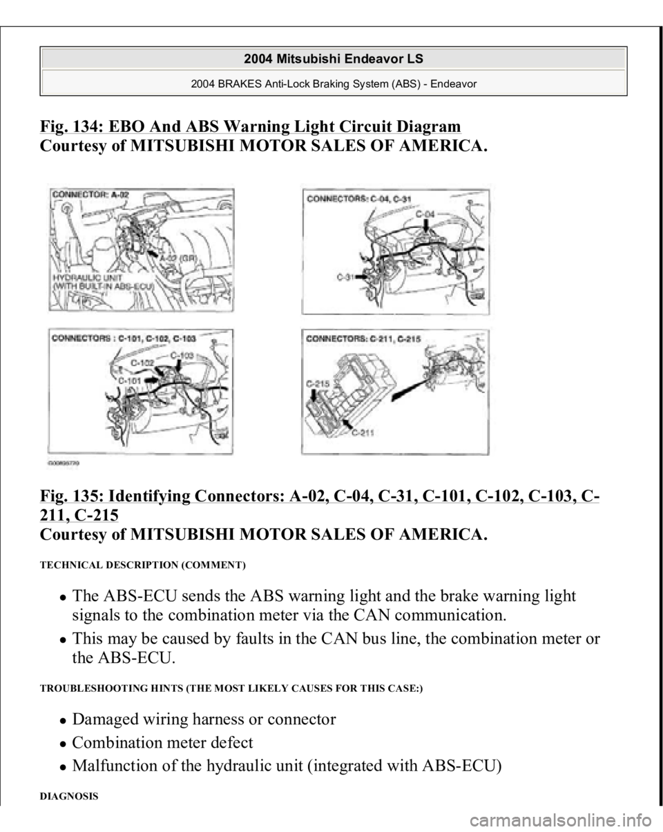
Fig. 134: EBO And ABS Warning Light Circuit Diagram
Courtesy of MITSUBISHI MOTOR SALES OF AMERICA.
Fig. 135: Identifying Connectors: A
-02, C
-04, C
-31, C
-101, C
-102, C
-103, C
-
211, C
-215
Courtesy of MITSUBISHI MOTOR SALES OF AMERICA.
TECHNICAL DESCRIPTION (COMMENT)
The ABS-ECU sends the ABS warning light and the brake warning light
signals to the combination meter via the CAN communication. This may be caused by faults in the CAN bus line, the combination meter or
the ABS-ECU.
TROUBLESHOOTING HINTS (THE MOST LIKELY CAUSES FOR THIS CASE:)
Damaged wiring harness or connector Combination meter defect Malfunction of the hydraulic unit (integrated with ABS-ECU)
DIAGNOSIS
2004 Mitsubishi Endeavor LS
2004 BRAKES Anti-Lock Braking System (ABS) - Endeavor
Page 255 of 3870
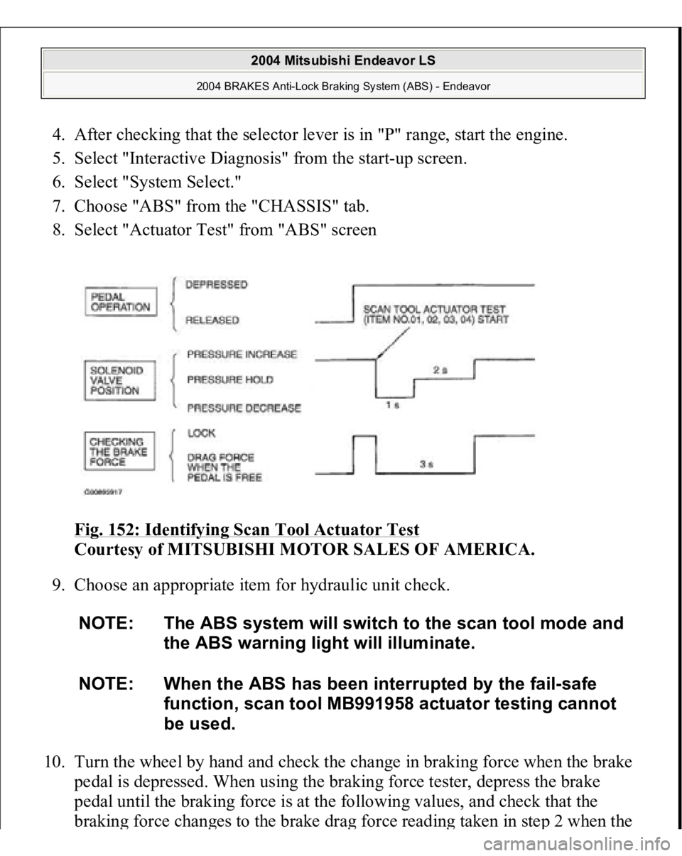
4. After checking that the selector lever is in "P" range, start the engine.
5. Select "Interactive Diagnosis" from the start-up screen.
6. Select "System Select."
7. Choose "ABS" from the "CHASSIS" tab.
8. Select "Actuator Test" from "ABS" screen
Fig. 152: Identifying Scan Tool Actuator Test
Courtesy of MITSUBISHI MOTOR SALES OF AMERICA.
9. Choose an appropriate item for hydraulic unit check.
10. Turn the wheel by hand and check the change in braking force when the brake
pedal is depressed. When using the braking force tester, depress the brake
pedal until the braking force is at the following values, and check that the
brakin
g force chan
ges to the brake dra
g force readin
g taken in ste
p 2 when the
NOTE: The ABS system will switch to the scan tool mode and
the ABS warning light will illuminate.
NOTE: When the ABS has been interrupted by the fail-safe
function, scan tool MB991958 actuator testing cannot
be used.
2004 Mitsubishi Endeavor LS
2004 BRAKES Anti-Lock Braking System (ABS) - Endeavor
Page 702 of 3870
installation easier.
3. The master cylinder reservoir tank cap has been colored white to make
identification easier.
4. The ABS-ECU and hydraulic unit have been integrated to make them more
compact and light weight.
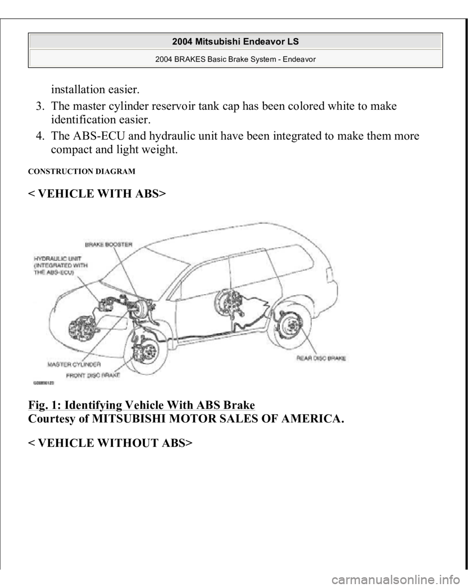
CONSTRUCTION DIAGRAM < VEHICLE WITH ABS>
Fig. 1: Identifying Vehicle With ABS Brake
Courtesy of MITSUBISHI MOTOR SALES OF AMERICA.
< VEHICLE WITHOUT ABS>
2004 Mitsubishi Endeavor LS
2004 BRAKES Basic Brake System - Endeavor
Page 727 of 3870
3. If the brake pedal height is not within the standard value, follow the procedure
below.
1. Disconnect the stoplight switch connector.
2. Remove the brake booster (Refer to MASTER CYLINDER
ASSEMBLY AND BRAKE BOOSTER
).
3. Adjust the brake pedal height by turning the clevis.
4. Install the brake booster (Refer to MASTER CYLINDER ASSEMBLY
AND BRAKE BOOSTER
).
5. Measure the brake pedal height, and ensure that the measured value is
within the specified value. When it is out of the specified value, repeat
Ste
ps 3 -6 .
NOTE: With the master cylinder and brake pipe connected,
remove the brake booster only.
NOTE: When the clevis is turned 180 degrees, the pedal
height is changed approximately 2.2 mm (0.09 in).
2004 Mitsubishi Endeavor LS
2004 BRAKES Basic Brake System - Endeavor
Page 728 of 3870
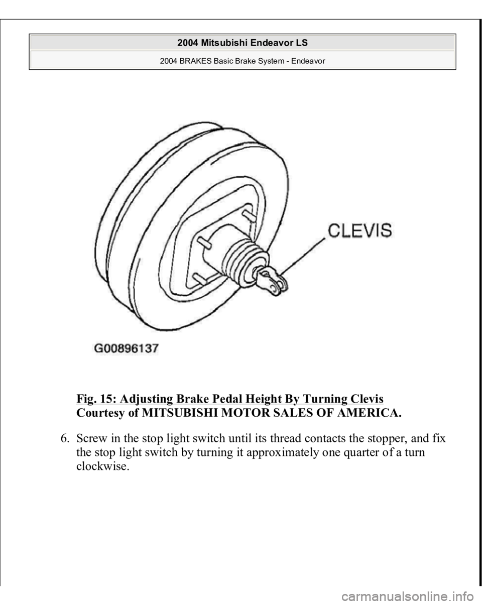
Fig. 15: Adjusting Brake Pedal Height By Turning Clevis
Courtesy of MITSUBISHI MOTOR SALES OF AMERICA.
6. Screw in the stop light switch until its thread contacts the stopper, and fix
the stop light switch by turning it approximately one quarter of a turn
clockwise.
2004 Mitsubishi Endeavor LS
2004 BRAKES Basic Brake System - Endeavor
Page 729 of 3870
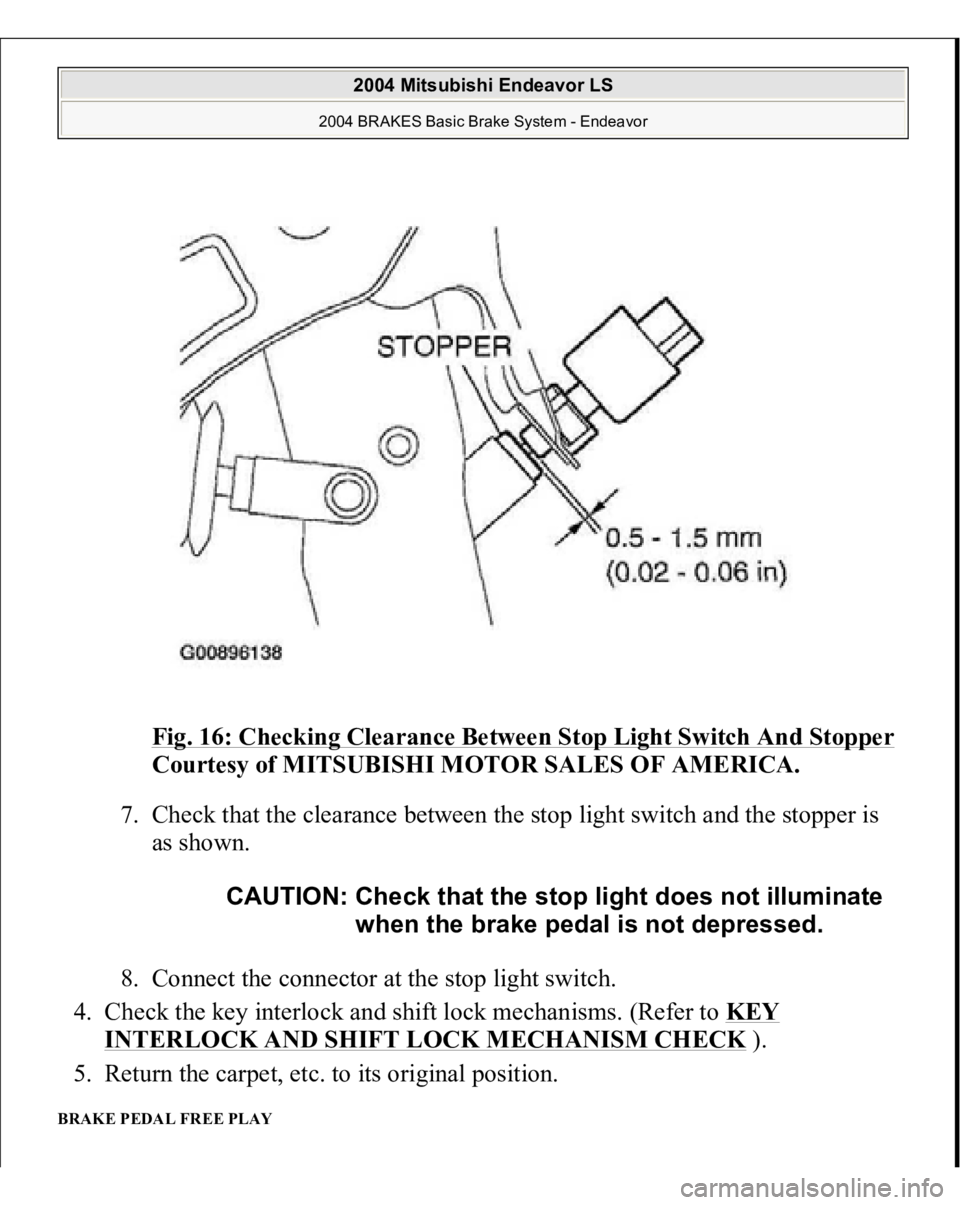
Fig. 16: Checking Clearance Between Stop Light Switch And Stopper
Courtesy of MITSUBISHI MOTOR SALES OF AMERICA.
7. Check that the clearance between the stop light switch and the stopper is
as shown.
8. Connect the connector at the stop light switch.
4. Check the key interlock and shift lock mechanisms. (Refer to KEY
INTERLOCK AND SHIFT LOCK MECHANISM CHECK
).
5. Return the carpet, etc. to its original position.
BRAKE PEDAL FREE PLAY
CAUTION: Check that the stop light does not illuminate
when the brake pedal is not depressed.
2004 Mitsubishi Endeavor LS
2004 BRAKES Basic Brake System - Endeavor
Page 732 of 3870
2. If the brake pedal play is not within the standard value, check the following,
and adjust or replace if necessary:
Excessive play between the brake pedal and the clevis pin, or between the
clevis pin and the brake booster operating rod Brake pedal height Installation position of the stop light switch, etc.
CLEARANCE BETWEEN BRAKE PEDAL AND DASH PANEL 1. Turn up the carpet, etc. under the brake pedal.
2. Start the engine, depress the brake pedal with approximately 500 N (112
pounds) of force, and measure the clearance between the brake pedal and the
dash panel.
Standard value: 110 mm (4.33 inches) or more [From the surface of dash
panel to the face of
pedal
pad]
2004 Mitsubishi Endeavor LS
2004 BRAKES Basic Brake System - Endeavor