MITSUBISHI GALANT 1989 Service User Guide
Manufacturer: MITSUBISHI, Model Year: 1989, Model line: GALANT, Model: MITSUBISHI GALANT 1989Pages: 1273, PDF Size: 37.62 MB
Page 11 of 1273
GENERAL - Vehicle Identification00-9
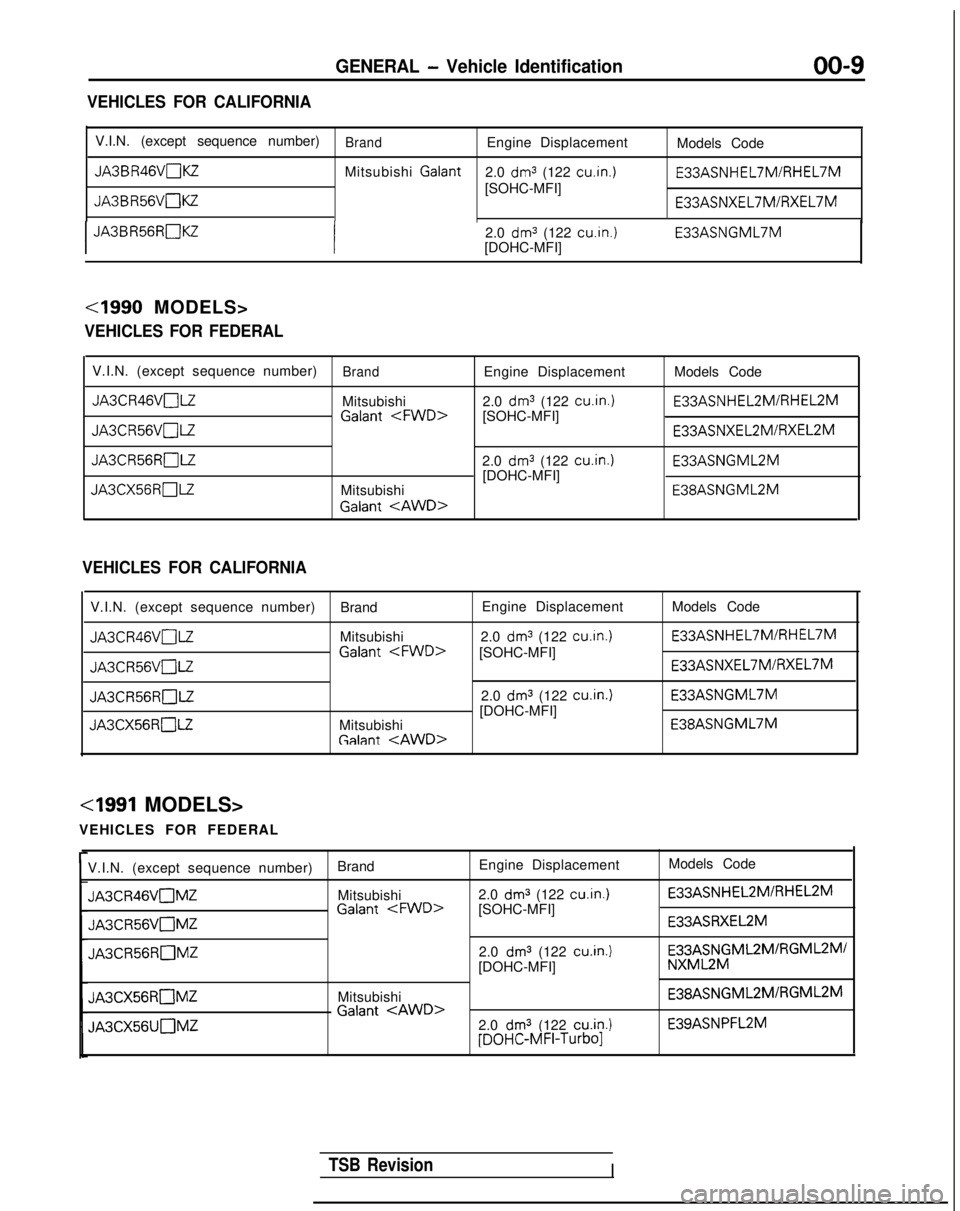
VEHICLES FOR CALIFORNIA
V.I.N. (except sequence number)BrandEngine DisplacementModels Code
JA3BR46VnKZMitsubishi Galant
2.0 dm3 (122 cu.in.1 E33ASNHEL7MIRHEL7M
[SOHC-MFI]
JA3BR56VnKZ E33ASNXEL7MlRXEL7M
I
JA3BR56RC]KZ
2.0
dm3 (122 cu.in.)
[DOHC-MFI] E33ASNGML7M
VEHICLES FOR FEDERAL
V.I.N. (except sequence number)BrandEngine Displacement
Models CodeJASCR46VOl-Z
Mitsubishi2.0
dm3 (122 cu.in.1 E33ASNHEL2MIRHEL2M
Galant
JA3CR56RnLZ2.0 dm3 (122 cuin.)
E33ASNGML2M
[DOHC-MFI]
JA3CX56RnLZMitsubishi E38ASNGML2M
Galant
tAWD>
VEHICLES FOR CALIFORNIA
V.I.N. (except sequence number)
BrandEngine Displacement
Models CodeJA3CR46VC]LZ
Mitsubishi
2.0
dm3 (122 cuin.) E33ASNHEL7MlRHEL7M
Galant
JA3CR56RnLZ2.0 dm3 (122 cuin.)
E33ASNGML7M
[DOHC-MFI] JA3CX56ROLZ
Mitsubishi E38ASNGML7M
Galant
VEHICLES FOR FEDERAL
V.I.N. (except sequence number) BrandEngine Displacement
Models CodeJA3CR46VC]MZ
Mitsubishi
2.0
dm3 (122 cu.in.1 E33ASNHEL2MlRHEL2M
Galant
JA3CR56VnMZE33ASRXEL2M
JA3CR56RnMZ2.0 dm3 (122 cu.in.1[DOHC-MFI]
E33;;$ML2MIRGML2Ml
JA3CX56RnMZMitsubishi E38ASNGML2MlRGML2M
Galant
JA3CX56UOMZ2.0 dm3 (122 cuin.)E39ASNPFL2M [DOHC-MFI-Turbo1
TSB RevisionI
Page 12 of 1273
00-l 0
GENERAL - Vehicle Identification
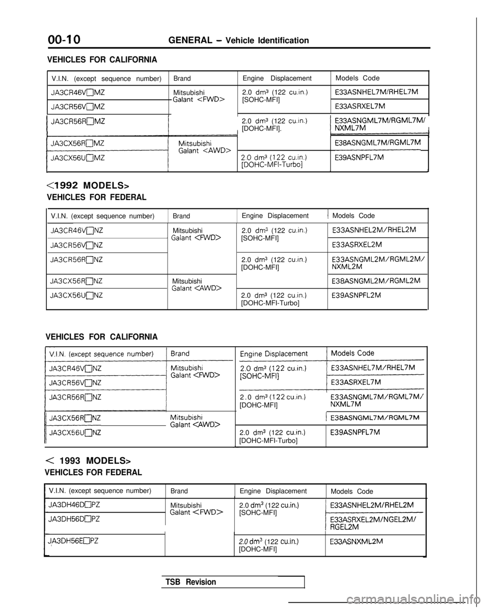
VEHICLES FOR CALIFORNIA
V.I.N. (except sequence number)BrandEngine Displacement
Models Code
JA3CR46VnMZMitsubishi2.0 dm3 (122 cuin.) E33ASNHEL7MIRHEL7M
Galant
E33ASRXEL7M
IJA3CR56RnMZ2.0 dm3 (122 cuin.)[DOHC-MFI]I
FX3;;$ML7MIRGML7M/
I
11 ““nUPi”WD> 200.0~‘~~~22x~.):::::?:;IRGMVM .
1I,J
<1992 MODELS>
VEHICLES FOR FEDERAL
V.I.N. (except sequence number)Brand
JA3CR46VaNZ
JA3CR56VuNZ
JA3CR56RONZ
JA3CX56R[ZlNZ
JA3CX56UnNZ
Mitsubishi1 Galant
MitsubishiGalant
Engine Displacement
2.0
dm3 (122 cu.in.)[SOHC-MFI]
2.0
dm3 (122 cu.in.)[DOHC-MFI]
2.0
dm3 (122 cu.in.)[DOHC-MFI-Turbo]
1 Models Code E33ASNHEL2MIRHEL2M
E33ASRXEL2M
E3gf2N$ML2M/AGML2M/
E38ASNGML2M/RGML2M
E39ASNPFL2M
VEHICLES FOR CALIFORNIA
V.I.N. (except sequence number)
~
I
JA3CR56RnNZ
j Mw;wm;;:1 g;;gwo,
< 1993 MODELS>
VEHICLES FOR FEDERAL
2.0 dm3
(122
cu.in.)
[DOHC-MFI]E33ASNGML7M/RGML7M/ NXML7M
2.0
dms (122 cu.in.)
[DOHC-MFI-Turbo] E39ASNPFL7M
V.I.N. (except sequence number)
BrandEngine Displacement Models Code
JA3DH46DnPZ
JA3DH56DnPZ
Mitsubishi Galant
2.0 dm3 (122 cu.in.)[SOHC-MFI]
2.0
dm3 (122 win.)[DOHC-MFI] E33ASNXML2M
TSB Revision
Page 13 of 1273
GENERAL - Vehicle Identification00-l 1
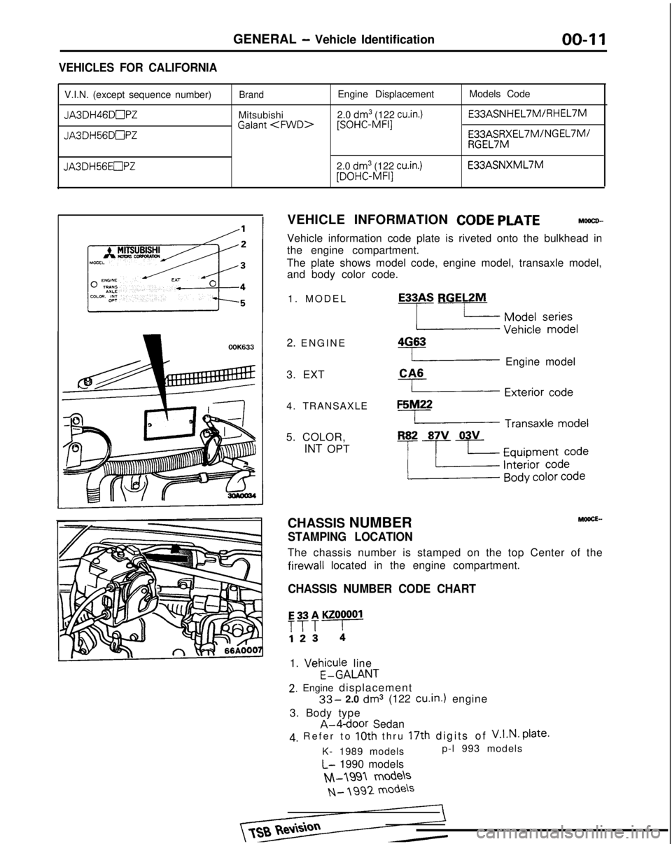
VEHICLES FOR CALIFORNIA
V.I.N. (except sequence number)
JA3DH46DmPZ
JA3DH56DnPZ
JA3DH56EOPZ
Brand
Mitsubishi Galant
Engine Displacement
2.0
dm3 (122 cu.in.) [SOHC-MFI]
2.0
dm3 (122 cu.in.) [DOHC-MFI]
Models Code E33ASNHEL7M/RHEL7M
b;$,,%&EL7M/NGEL7M/
E33ASNXML7M
VEHICLE INFORMATION
CODE PLATEMOOCD-
Vehicle information code plate is riveted onto the bulkhead in
the engine compartment.
The plate shows model code, engine model, transaxle model, and body color code.
1. MODE
L
2. ENGINE
3. EXT
4. TRANSAXLE
5. COLOR,
INT OPT
E33AS RGELZM
-LzI ~~~~~S$)y& 4G63
( Engine model
CA6
I Exterior co&
F5M22
L Transaxle model
R82 87V 03V
-p+cf~~l;;
CHASSIS NUMBERMOOCE-
STAMPING LOCATION
The chassis number is stamped on the top Center of the
firewall
located in the engine compartment.
CHASSIS NUMBER CODE CHART E33AKZOOOOl
T?T!
1.
Vehicule
line
E-GALANT
2. Engine displacement
33- 2.0 dm3 (122 cu.in.)
engine
3. Body type
A-4-door Sedan
4, Refer to 10th thru 17th digits of V.I.N.
Plate.
K- 1989 models p-l 993 models
L- 1990 models
M-1991 models
N- 199'2 mode\s
Page 14 of 1273
GENERAL - Vehicle Identification
OOA0192
Theft protection label
For
orIgInal parts
OOK619
For replacement parts
OOK621
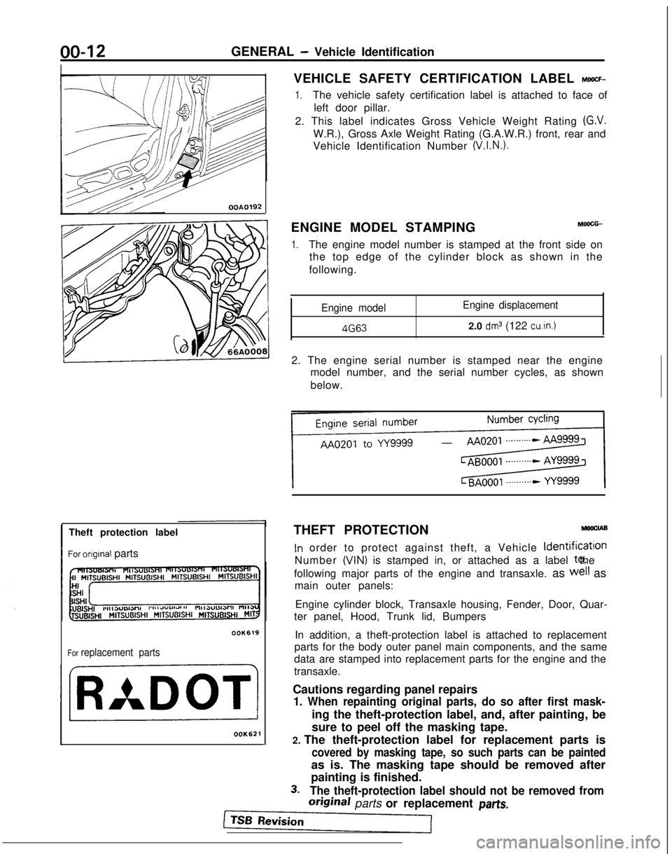
VEHICLE SAFETY CERTIFICATION LABEL MWCF-
1.The vehicle safety certification label is attached to face of left door pillar.
2. This label indicates Gross Vehicle Weight Rating
(G.V.
W.R.), Gross Axle Weight Rating (G.A.W.R.) front, rear and
Vehicle Identification Number
(V.I.N.).
ENGINE MODEL STAMPINGM6ocG-.
1.The engine model number is stamped at the front side on the top edge of the cylinder block as shown in the
following.
Engine model Engine displacement 4G63
2.0
dm3 (122 cu.in.)
2. The engine serial number is stamped near the engine
model number, and the serial number cycles, as shown
below.
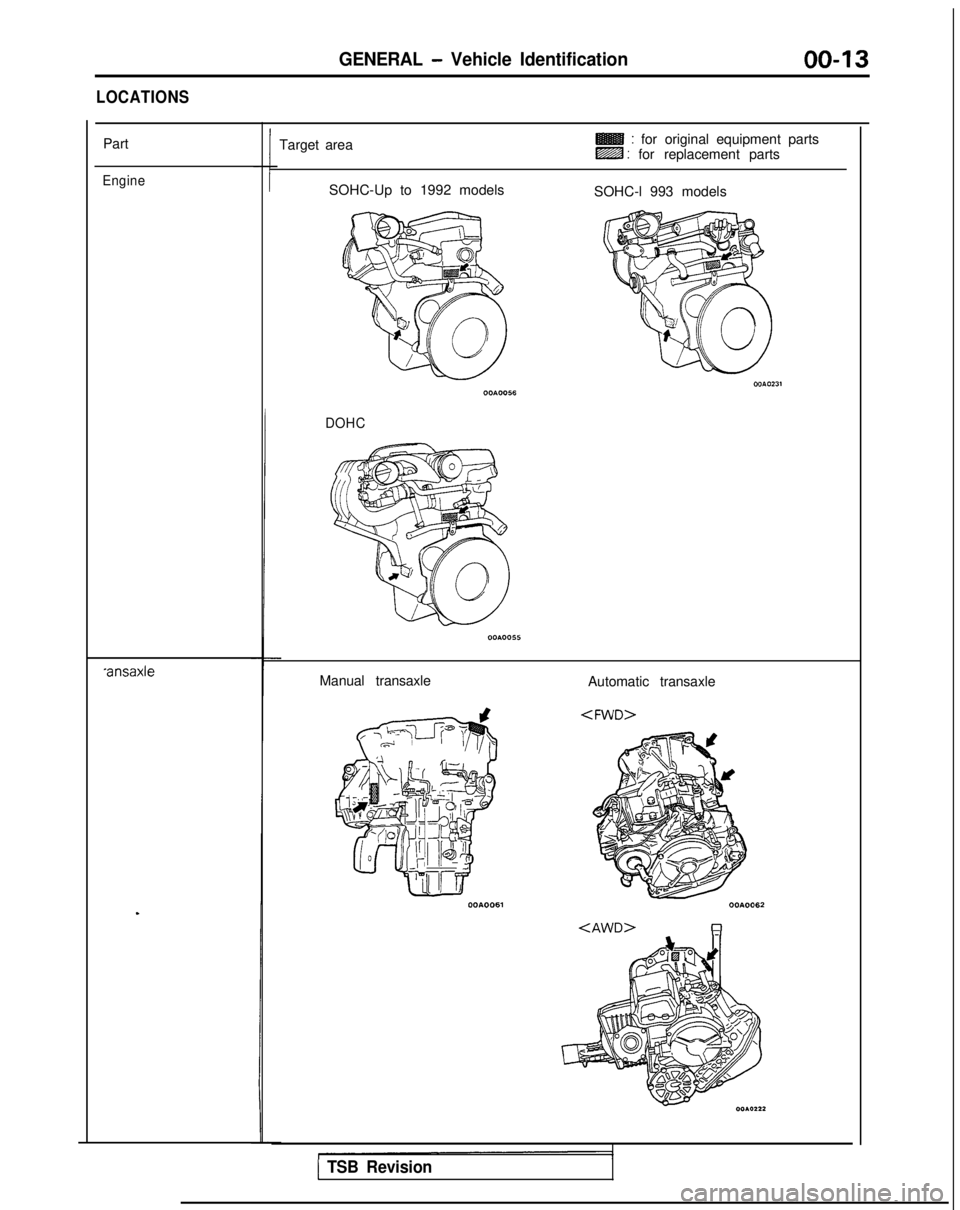
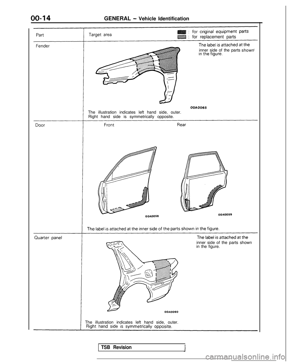
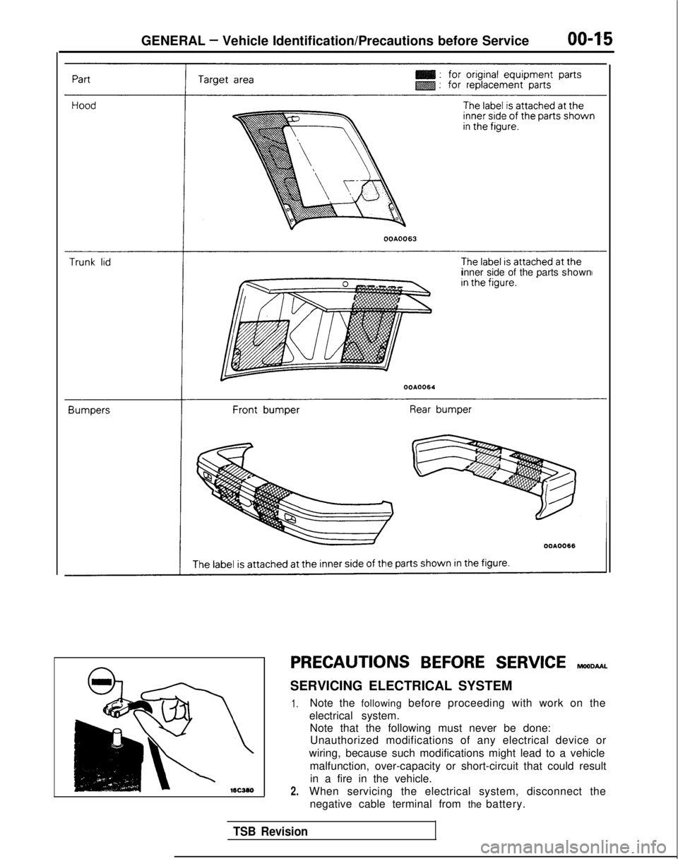
THEFT PROTECTION
MwclA9
In order to protect against theft, a Vehicle ldentificatlon
Number
(VIN) is stamped in, or attached as a label to, the
following major parts of the engine and transaxle. as
well as
main outer panels:
Engine cylinder block, Transaxle housing, Fender, Door, Quar-
ter panel, Hood, Trunk lid, Bumpers
In addition, a theft-protection label is attached to replacement
parts for the body outer panel main components, and the same
data are stamped into replacement parts for the engine and the
transaxle.
Cautions regarding panel repairs
1. When repainting original parts, do so after first mask-
ing the theft-protection label, and, after painting, be
sure to peel off the masking tape.
2. The theft-protection label for replacement parts is
covered by masking tape, so such parts can be painted
as is. The masking tape should be removed after
painting is finished.
3.The theft-protection label should not be removed from
original parts or replacement par-&
Page 15 of 1273
GENERAL - Vehicle Identification00-13
LOCATIONS
Part
Engine
*ansaxle
.
Target area: for original equipment partsLZZB : for replacement parts
SOHC-Up to 1992 models SOHC-l 993 models
DOHC
Manual transaxle Automatic transaxle
1 TSB Revision
Page 16 of 1273
GENERAL - Vehicle Identification
@g :for replacement parts
inner side of the parts
shown
OOA0065
The illustration indicates left hand side, outer.
Right hand side is symmetrically opposite.
OOA0056OOAOO59
inner side of the parts shown
in the figure.
The illustration indicates left hand side, outer.
TSB Revision
Page 17 of 1273
GENERAL - Vehicle Identification/Precautions before Service
OOA0063
inner side of the parts
shown
PRECAUTIONS BEFORE SERVICE reomu~
SERVICING ELECTRICAL SYSTEM
1.
2.
Note the following before proceeding with work on the
electrical system. Note that the following must never be done:Unauthorized modifications of any electrical device or
wiring, because such modifications might lead to a vehicle malfunction, over-capacity or short-circuit that could resultin a fire in the vehicle.
When servicing the electrical system, disconnect the negative cable terminal from the battery.
TSB Revision
Page 18 of 1273
00-l 6GENERAL - Precautions before Service
Caution
1. Before connecting or disconnecting the negative
cable, be sure to turn off the ignition switch and the
lighting switch.
(If this is not done,there is the possibility of
semiconductor parts being damaged.)
2.For MFI-equipped models, after completion of the
work steps [when the battery’s negative (-) termi-
nal is connected], warm up the engine and allow it
to idle for approximately five minutes under the
conditions described below, in order to stabilize
engine control conditions, and then check to be
sure that the idling is satisfactory.
Engine coolant temperature:
85-95X (185-203°F)
Lights, electric fans, accessories: OFF
Transaxle: neutral position (A/T models: “N” or
“P”)
Steering wheel:neutral (center) position
mm (tn.1
Scan Tool(Multi-use tester
ROM pack
1
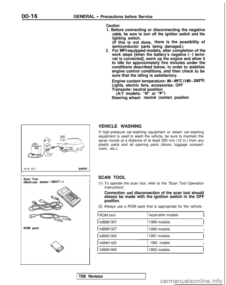
VEHICLE WASHING
If high-pressure car-washing equipment or steam car-washing
equipment is used to wash the vehicle, be sure to maintain the
spray nozzle at a distance of at least 300 mm (12 in.) from any plastic parts and all opening parts (doors, luggage compart-
ment, etc.).
SCAN TOOL (1) To operate the scan tool, refer to the “Scan Tool Operation Instructions”.
Connection and disconnection of the scan tool should
always be made with the ignition switch in the OFF
position.
(2) Always use a ROM pack that is appropriate for the vehicle.
1 ROM oack1 Aoblicable models
1 MB9913071 1989 modelsI
1 MB9913271 1990 modelsI
1 MB991359( 1991 models
IMB991 4231992 modelsI
1 MB9914661 1993 models
TSB Revision
Page 19 of 1273
GENERAL - Towina and Hoisting
00-l 7
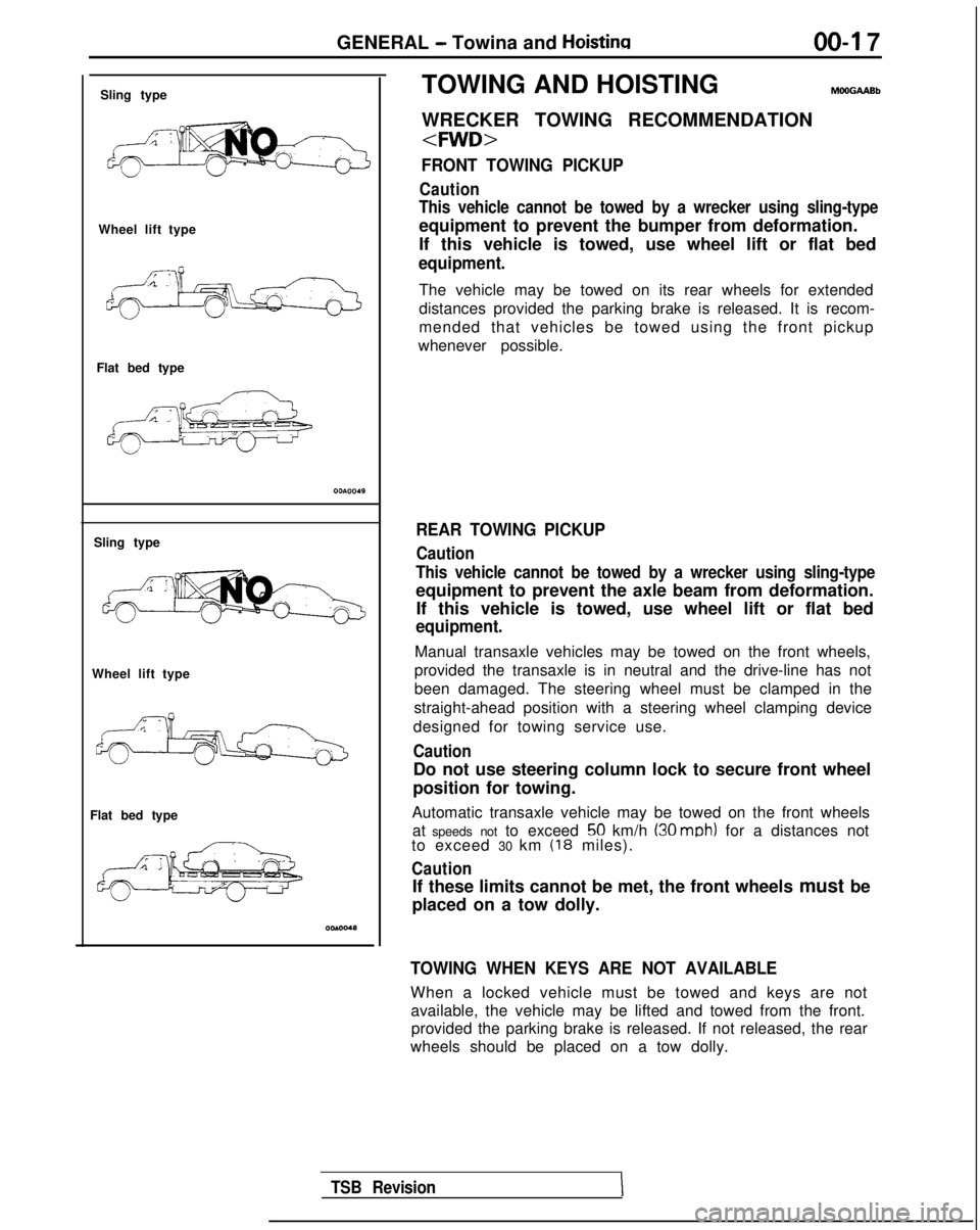
Sling type
Wheel lift type
Flat bed type
Sling type
Wheel lift type
Flat bed type TOWING AND HOISTING
WRECKER TOWING RECOMMENDATION
FRONT TOWING PICKUP
Caution
This vehicle cannot be towed by a wrecker using sling-type
equipment to prevent the bumper from deformation.
If this vehicle is towed, use wheel lift or flat bed
equipment.
The vehicle may be towed on its rear wheels for extended
distances provided the parking brake is released. It is recom-
mended that vehicles be towed using the front pickup
whenever possible.
REAR TOWING PICKUP
Caution
This vehicle cannot be towed by a wrecker using sling-type
equipment to prevent the axle beam from deformation. If this vehicle is towed, use wheel lift or flat bed
equipment.
Manual transaxle vehicles may be towed on the front wheels,
provided the transaxle is in neutral and the drive-line has not
been damaged. The steering wheel must be clamped in the
straight-ahead position with a steering wheel clamping device
designed for towing service use.
Caution
Do not use steering column lock to secure front wheel
position for towing.
Automatic transaxle vehicle may be towed on the front wheels at speeds not to exceed
50 km/h (30 mob) for a distances not
to exceed 30 km (18 miles).
Caution
If these limits cannot be met, the front wheels must be
placed on a tow dolly.
TOWING WHEN KEYS ARE NOT AVAILABLE
When a locked vehicle must be towed and keys are not available, the vehicle may be lifted and towed from the front.provided the parking brake is released. If not released, the rear
wheels should be placed on a tow dolly.
TSB Revision
Page 20 of 1273
00-l 8GENERAL - Towing and Hoisting
SAFETY PRECAUTIONS
The following precautions should be taken when towing thevehicle.
1.DO NOT LIFT OR TOW THE VEHICLE BY ATTACHING TO
OR WRAPPING AROUND THE BUMPER.
2. Any loose or protruding parts of damaged vehicle such as hoods, doors, fenders, trim, etc., should be secured prior to
moving the vehicle.
3.Operator should refrain from going under a vehicle while it
is lifted by the towing equipment, unless the vehicle in
adequately supported by satefy stands.
4. Never allow passengers to ride in a towed vehicle. 5. State and local rules and regulations must be followed when towing a vehicle.
Refer to the section “Special Handling Instructions for AWD
Models”.
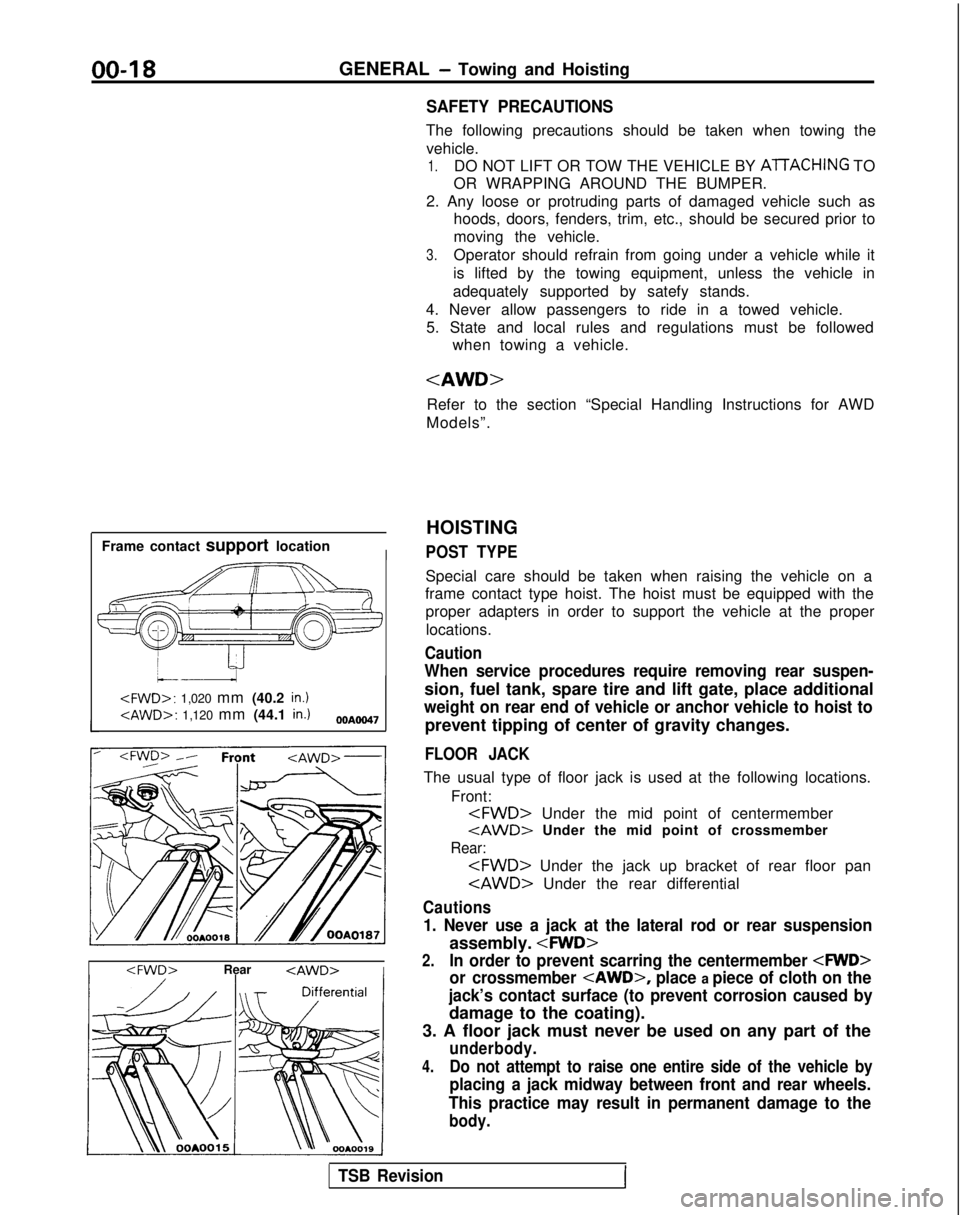
Frame contact support location
I
HOISTING
POST TYPE
Special care should be taken when raising the vehicle on a
frame contact type hoist. The hoist must be equipped with the
proper adapters in order to support the vehicle at the proper
locations.
Caution
When service procedures require removing rear suspen-
sion, fuel tank, spare tire and lift gate, place additional
weight on rear end of vehicle or anchor vehicle to hoist to
prevent tipping of center of gravity changes.
FLOOR JACK
The usual type of floor jack is used at the following locations.
Front:
tAWD> Under the mid point of crossmember
Rear:
Cautions
1. Never use a jack at the lateral rod or rear suspension
assembly.
2.In order to prevent scarring the centermember
or crossmember
place a piece of cloth on the
jack’s contact surface (to prevent corrosion caused by
damage to the coating).
3. A floor jack must never be used on any part of the
underbody.
4.Do not attempt to raise one entire side of the vehicle by
placing a jack midway between front and rear wheels.
This practice may result in permanent damage to the
body.
TSB RevisionI