fuel pump MITSUBISHI GALANT 1989 Service Owner's Manual
[x] Cancel search | Manufacturer: MITSUBISHI, Model Year: 1989, Model line: GALANT, Model: MITSUBISHI GALANT 1989Pages: 1273, PDF Size: 37.62 MB
Page 188 of 1273

13-46 FUEL SYSTEM
FUEL PUMP
MlBYEAB
@ Component side connector
-
\
1Fuel pump M
$
1
I
-
Multiportfuel
injection
relay
Component side
7/-/
L2 :<
\
6’
_!
4,
@connector,
I-~ i1SlLl”’-------.,\OFF I OIL
,’e-
\/ \/1\/ \/5 1 2
’
-
I
IT-----
-
1!
check terminal -5EL1200j
Engine
control module @ Harness side
connector
@ Harness side
connector
I
6FU1236
Engine control module connector OlLO838
TSB RevisionI
Page 189 of 1273
FUEL SYSTEM
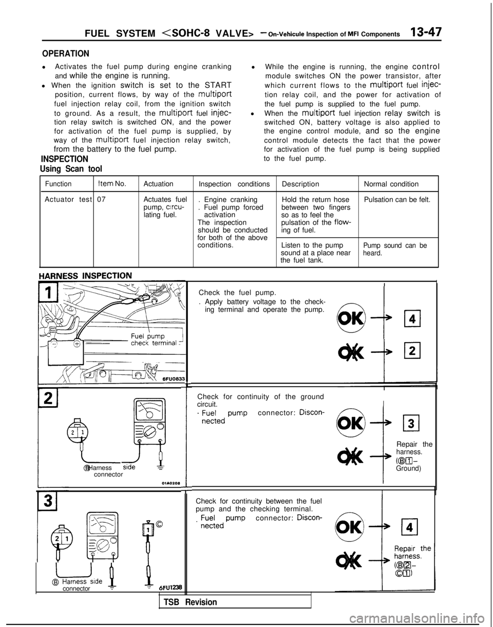
OPERATION
l
Activates the fuel pump during engine cranking
and while the engine is running.
l When the ignition switch is set to the START
position, current flows, by way of the
multiport
fuel injection relay coil, from the ignition switch
to ground. As a result, the
multiport fuel injec-
tion relay switch is switched ON, and the power
for activation of the fuel pump is supplied, by
way of the
multiport fuel injection relay switch,
from the battery to the fuel pump.
INSPECTION
Using Scan tool
l While the engine is running, the engine control
module switches ON the power transistor, after
which current flows to the
multiport fuel injec-
tion relay coil, and the power for activation of
the fuel pump is supplied to the fuel pump.
l When the
multiport fuel injection relay switch is
switched ON, battery voltage is also applied to
the engine control module, and so the engine
control module detects the fact that the power
for activation of the fuel pump is being supplied
to the fuel pump.
Function Item
No.
Actuation Inspection conditions DescriptionNormal condition
Actuator test 07 Actuates fuel
. Engine cranking Hold the return hosePulsation can be felt.
pump, clrcu-
. Fuel pump forced between two fingers
lating fuel. activation
so as to feel the
The inspection pulsation of the
flow-should be conducteding of fuel.
for both of the above conditions. Listen to the pump
Pump sound can besound at a place nearheard.the fuel tank.
Check for continuity of the ground
circuit.
I
. ;E;;,, pumpconnector: Discon-
2
1
Y-
!
Repair theharness.
@El- @ HarnessGround)connector
O~AOZOl3
I
Check for continuity between the fuel
pump and the checking terminal.
connector: Discon-
1
@uide 1
B
0. ;;;;,,
pump
L
Check the fuel pump.
. Apply battery voltage to the check-
ing terminal and operate the pump.
!I:7
OK
connector :1 = 6FUl238
TSB Revision
Page 190 of 1273
13-48 FUEL SYSTEM
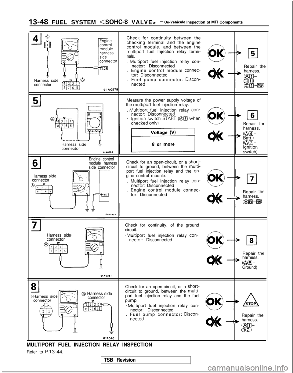
Check for continuity between the
checking terminal and the engine
control module, and between the
multiport fuel Injection relay termi-nals.
connector
01 A0579
.
Multiport fuel injection relay con-
nector: Disconnected
. Engine control module connec-
tor: Disconnected
. Fuel pump connector: Discon-
netted
Repair the
harness.
Measure the power supply voltage of
the
multiport fuel injection relay.
.
Multiport fuel injection relay con-
Harness sideconnector
Engine control
module harnessCheck for an open-circuit, or a short-
side connectorcircuit to ground, between the multi-port fuel injection relay and the en-
gine control module.
. Multiport fuel injection relay con-
nectar:
Disconnected
. Engine control module connec-
tor: Disconnected Repair
the-+ harness.
(@a-8)
Harness side
connector
@
Check for continuity, of the ground
circuit.
- Multiport fuel injection relay con-
nectar:
Disconnected.
Repair
theharness.
a vmil-Ground)
@ Harness sideconnector
Check for an open-circuit, or a short-circuit to ground, between the multi-port fuel injection relay and the fuel
w-we Multiport fuel injection relay con-
nector: Disconnected
. Fuel pump connector: Discon-
nettedRepair the-+ harness.
GilIl-@El)T
OlA0401
MULTIPORT FUEL INJECTION RELAY INSPECTION
Refer to P.13-44.
TSB Revision
Page 204 of 1273
13-62 FUEL SYSTEM
INSPECTION
Using Scan tool
FunctionItem No.
Data reading 26 Data display
Inspection conditions Switch
status Ignition
switch: ON
(Check after pumping
accelerator several times.) Throttle valve
Normal indication
To idle position
ON
Slightly openedOFF
HARNESS INSPECTION
Harness sideconnector
Y
OlR085
motor connector1 FUO480
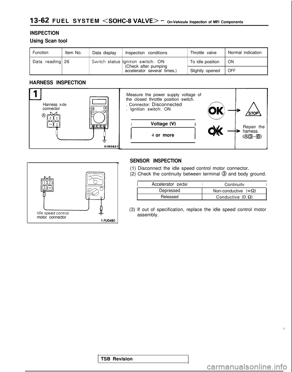
Measure the power supply voltage of
the closed throttle position switch.
. Connector: Disconnected
. Ignition switch: ON
IVoltage (V)I
I4 or moreI
Repair theharness.
c@a-m)
SENSOR INSPECTION
(1) Disconnect the idle speed control motor connector.
(2) Check the continuity between terminal
@ and body ground.
TSB Revision
IAccelerator DedalIContinuitvI
DepressedNon-conductive (42)
Released Conductive (0. Q)
(3) If out of specification, replace the idle speed control motor
assembly.
Page 224 of 1273
13-82 FUEL SYSTEM
OPERATION
l The power-steering pressure switch functions
to convert data as to whether there is or is not apower steering load to LOW-or HIGH-level vol-
tage, and the resulting signals are input to the engine control module. The engine control mod-
ule, based upon those signals, regulates the
idle-speed control motor. l The battery voltage within the engine control
module is applied, by way of the resistance, to
the power-steering pressure switch. When
steering maneuvers are made, the pressure of
the power-steering oil increases, thus switching
ON the power-steering pressure switch, with
the result that the current is grounded. As a re-
sult, the power-steering pressure switch vol-
tage changes from HIGH level to LOW level.
INSPECTION I) Using Scan tool
Function
Item No.
Data reading 27
Data displayInspection conditions Steering wheelNormal indication
Switch status Engine: IdlingSteering wheel idle stateOFF
During steering wheelONoperation
(2) Checking Oil Pressure
Steering wheel
Straight forward
Turned
Oil pump delivery pressure (ref. value)
less than 1,470- 1,961 kPa (213-284 psi)
more than
1,470- 1,961 kPa (213-284 psi)
HARNESS INSPECTION
I-E-I
Harness side connector 6 0
@=- -0
Q
4 1
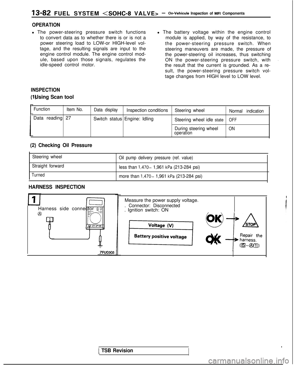
Measure the power supply voltage.
. Connector: Disconnected. Ignition switch: ON
[ TSB Revision
Page 244 of 1273
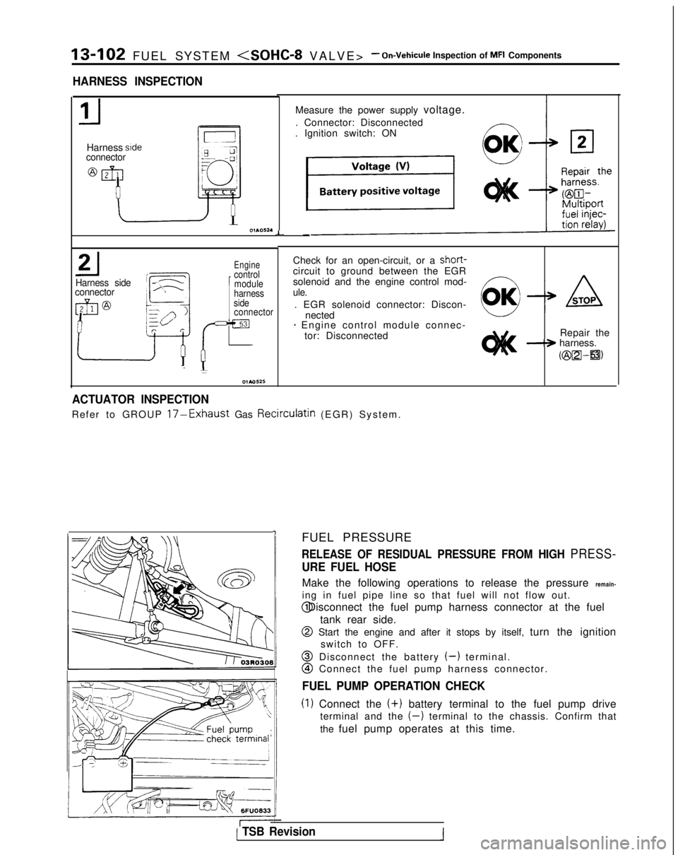
13-102 FUEL SYSTEM
- On-Vehicule Inspection of MFI Components
HARNESS INSPECTION
Harness sideconnector
L
Harness side
connector
Engine
1
control module
Check for an open-circuit, or a short-
circuit to ground between the EGR
solenoid and the engine control mod-
harnessule.side. EGR solenoid connector: Discon-connectornected+ Engine control module connec- tor: Disconnected Repair the
-+ harness.
Kzix2l-a)
-I
Measure the power supply voltage.
. Connector: Disconnected
. Ignition switch: ON
-
ACTUATOR INSPECTION
Refer to GROUP 17-Exhaust Gas Recirculatin (EGR) System
.
FUEL PRESSURE
RELEASE OF RESIDUAL PRESSURE FROM HIGH PRESS-
URE FUEL HOSE
Make the following operations to release the pressure remain-
ing in fuel pipe line so that fuel will not flow out. @ Disconnect the fuel pump harness connector at the fuel
tank rear side.
@ Start the engine and after it stops by itself, turn the ignitionswitch to OFF.
@ Disconnect the battery (-) terminal.
@I Connect the fuel pump harness connector.
FUEL PUMP OPERATION CHECK
(1) Connect the (+)
battery terminal to the fuel pump drive
terminal and the
(-) terminal to the chassis. Confirm that
the fuel pump operates at this time.
( TSB Revision1
Page 245 of 1273
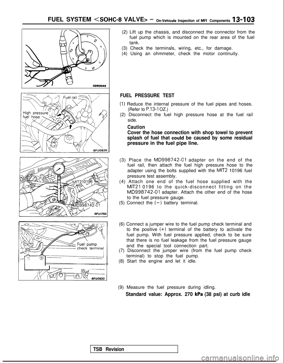
FUEL SYSTEM
TSB Revision
---
I g$qfq, tcJ-s6FUO633
(2) Lift up the chassis, and disconnect the connector from the
fuel pump which is mounted on the rear area of the fuel
tank.
(3) Check the terminals, wiring, etc., for damage.
(4) Using an ohmmeter, check the motor continuity.
FUEL PRESSURE TEST
(1) Reduce the internal pressure of the fuel pipes and hoses.
(Refer to P.13-1 OZ.)
(2) Disconnect the fuel high pressure hose at the fuel rail
side.
Caution
Cover the hose connection with shop towel to prevent
splash of fuel that
could be caused by some residual
pressure in the fuel pipe line.
(3) Place the
MD998742-01 adapter on the end of the
fuel rail, then attach the fuel high pressure hose to the
adapter using the bolts supplied with the
MIT2 10196 fuel
pressure test assembly.
(4) Attach one end of the fuel hose supplied with the
MIT21 0196 to the quick-disconnect fitting on the
MD998742-01 adapter. Attach the other end of the hose
to the fuel pressure gauge.
(5) Connect the
(-) battery terminal.
(6) Connect a jumper wire to the fuel pump check terminal and to the positive
(+) terminal of the battery to activate the
fuel pump. With fuel pressure applied, check to be sure
that there is no fuel leakage from the fuel pressure gauge
and the special tool connection part.
(7) Disconnect the jumper wire (from the fuel pump check
terminal) to stop the fuel pump.
(8) Start the engine and let it idle.
(9) Measure the fuel pressure during idling.
Standard value: Approx. 270 kPa (38 psi) at curb idle
Page 246 of 1273
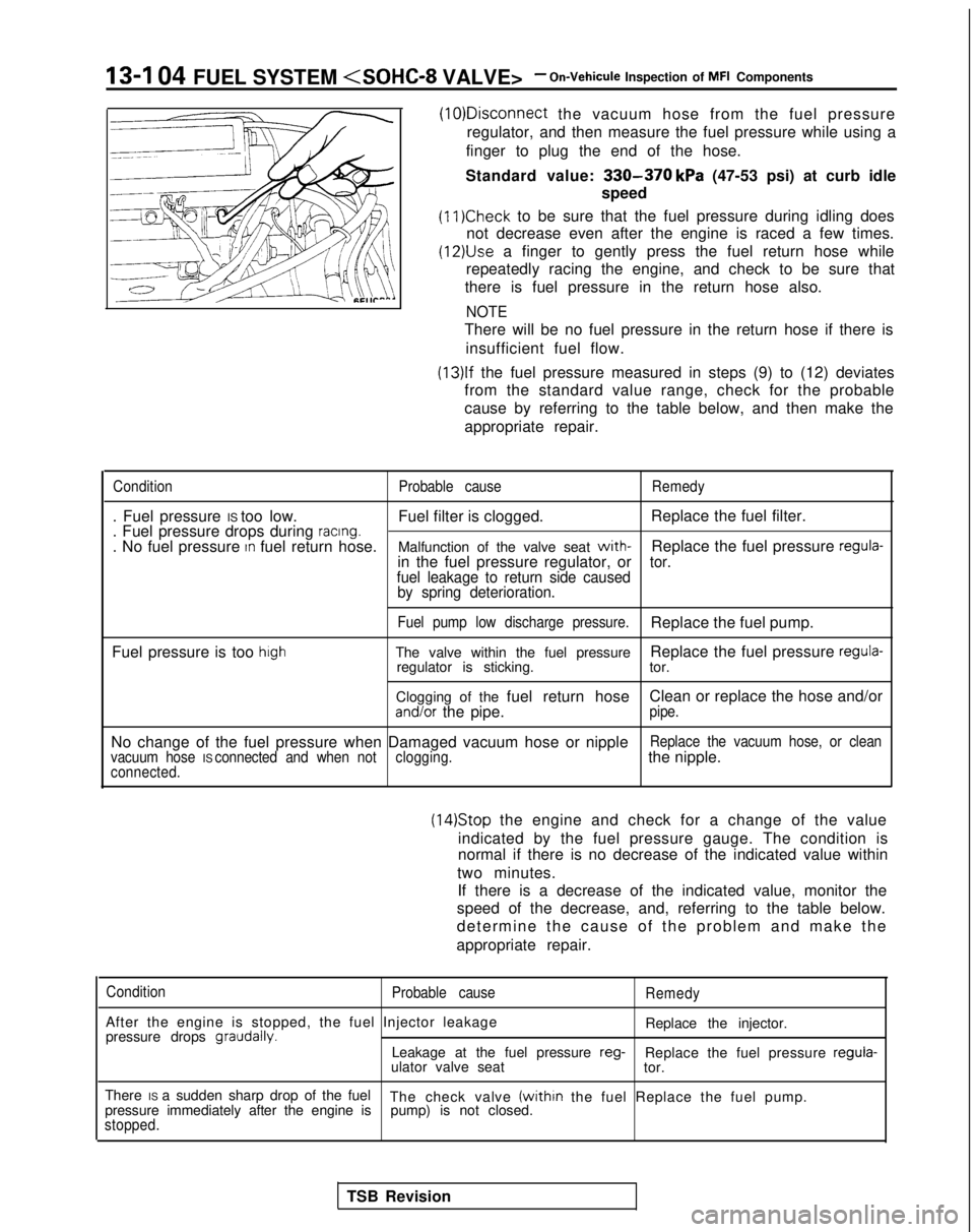
13-I 04 FUEL SYSTEM
the vacuum hose from the fuel pressure
regulator, and then measure the fuel pressure while using a
finger to plug the end of the hose.
Standard value:
330-370 kPa (47-53 psi) at curb idle
speed
(11)Check to be sure that the fuel pressure during idling does
not decrease even after the engine is raced a few times.
(12)&e a finger to gently press the fuel return hose while
repeatedly racing the engine, and check to be sure that
there is fuel pressure in the return hose also.
NOTE
There will be no fuel pressure in the return hose if there is
insufficient fuel flow.
(13)lf the fuel pressure measured in steps (9) to (12) deviates
from the standard value range, check for the probable
cause by referring to the table below, and then make the
appropriate repair.
Condition Probable causeRemedy
. Fuel pressure IS too low. Fuel filter is clogged.Replace the fuel filter.
. Fuel pressure drops during racing.. No fuel pressure In fuel return hose. Malfunction of the valve seat with-Replace the fuel pressure regula-in the fuel pressure regulator, ortor.
fuel leakage to return side caused by spring deterioration.
Fuel pump low discharge pressure.Replace the fuel pump.
Fuel pressure is too
highThe valve within the fuel pressure Replace the fuel pressure regula-regulator is sticking.
tor.
Clogging of the fuel return hose Clean or replace the hose and/or
and/or the pipe.pipe.
No change of the fuel pressure when Damaged vacuum hose or nippleReplace the vacuum hose, or clean
vacuum hose IS connected and when not clogging.the nipple.connected.
(14)Stop the engine and check for a change of the value
indicated by the fuel pressure gauge. The condition is
normal if there is no decrease of the indicated value within
two minutes. If there is a decrease of the indicated value, monitor the
speed of the decrease, and, referring to the table below.
determine the cause of the problem and make the
appropriate repair.
Condition Probable cause
After the engine is stopped, the fuel Injector leakage
pressure drops graudally.
Remedy
Replace the injector.
Leakage at the fuel pressure reg-
Replace the fuel pressure regula-
ulator valve seat tor.
There IS a sudden sharp drop of the fuel The check valve
(within the fuel Replace the fuel pump.
pressure immediately after the engine is pump) is not closed.
stopped.
TSB Revision
Page 247 of 1273
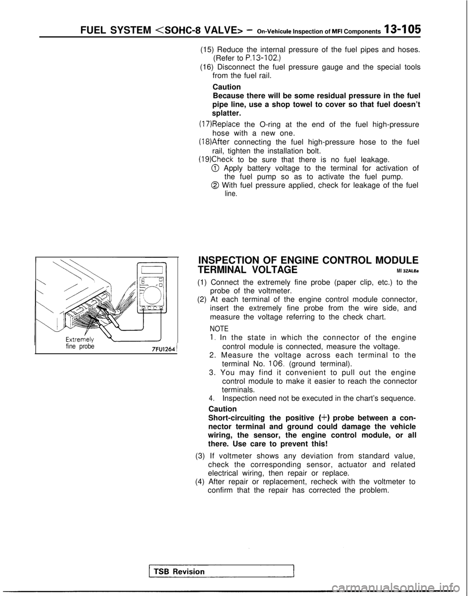
FUEL SYSTEM
fine probe7FU1264 1
(15) Reduce the internal pressure of the fuel pipes and hoses.
(Refer to
P.13-102.)
(16) Disconnect the fuel pressure gauge and the special toolsfrom the fuel rail.
Caution
Because there will be some residual pressure in the fuel
pipe line, use a shop towel to cover so that fuel doesn’t
splatter.
(17)Replace the O-ring at the end of the fuel high-pressure
hose with a new one. (18)After
connecting the fuel high-pressure hose to the fuel
rail, tighten the installation bolt.
(19)Check to be sure that there is no fuel leakage.
@ Apply battery voltage to the terminal for activation of the fuel pump so as to activate the fuel pump.
@ With fuel pressure applied, check for leakage of the fuel
line.
INSPECTION OF ENGINE CONTROL MODULE
TERMINAL VOLTAGEMl 3ZALBa
(1) Connect the extremely fine probe (paper clip, etc.) to the probe of the voltmeter.
(2) At each terminal of the engine control module connector,
insert the extremely fine probe from the wire side, and
measure the voltage referring to the check chart.
NOTE
1. In the state in which the connector of the engine
control module is connected, measure the voltage.
2. Measure the voltage across each terminal to the
terminal No. 106.
(ground terminal).
3. You may find it convenient to pull out the engine control module to make it easier to reach the connector
terminals.
4.Inspection need not be executed in the chart’s sequence.
Caution
Short-circuiting the positive
(+) probe between a con-
nector terminal and ground could damage the vehicle
wiring, the sensor, the engine control module, or all
there. Use care to prevent this!
(3) If voltmeter shows any deviation from standard value, check the corresponding sensor, actuator and related
electrical wiring, then repair or replace.
(4) After repair or replacement, recheck with the voltmeter to confirm that the repair has corrected the problem.
Page 248 of 1273
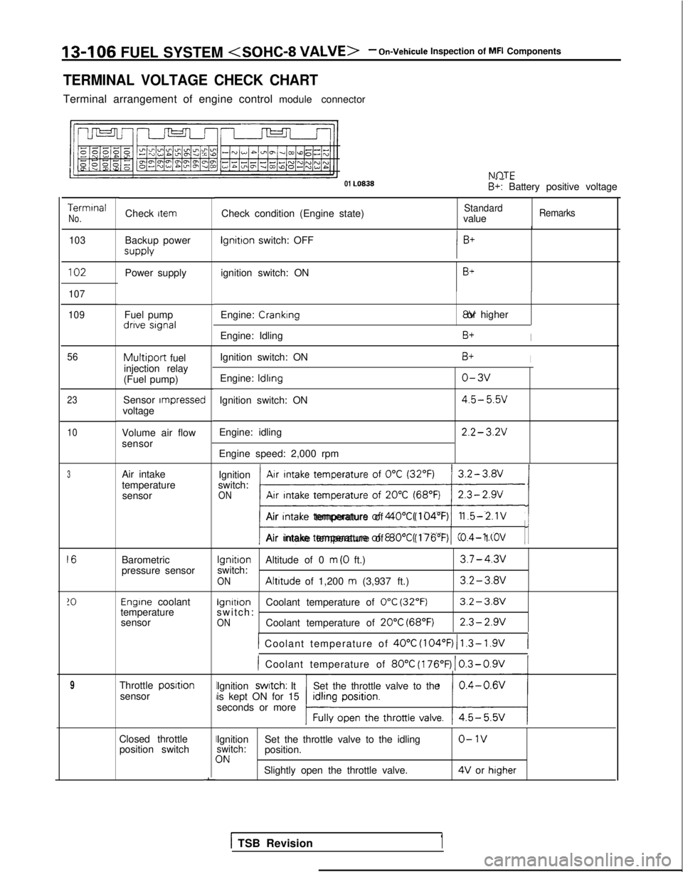
13-106
FUEL SYSTEM
TERMINAL VOLTAGE CHECK CHART
Terminal arrangement of engine control module connector NflTF
01 LO838
. .- -B+: Battery positive voltage
Terminal
No.Check condition (Engine state)StandardvalueRemarksCheck item
103
Backup power supply lgnitron
switch: OFF
102Power supply ignition switch: ONB+
107
109
Fuel pump dnve signal
Engine: Cranking 8V or higher
Engine: Idling
B+I
Ignition switch: ON
Engine:
ldlrng
Ignition switch: ON
Engine: idling
Engine speed: 2,000 rpm
B+I
o-3v
4.5- 5.5v
2.2- 3.2V
56
23
10
Multiport fuel
injection relay
(Fuel pump)
Sensor
rmpressecvoltage
Volume air flow
sensor
Air intake
temperature sensor Ignition
Air intake temperature of
0°C (32°F)switch:ONAir Intake temperature of 20°C (68°F); ji/
Air Intake temperature of 40°C (104°F)1.5-2.1V
Air intake temperature of 80°C (176’F)0.4- 1 .OV
Barometric
pressure sensor
Ignition
Altitude of 0 m (0 ft.)3.7-4.3vswitch:ON Altitude
of 1,200 m (3,937 ft.)3.2-3.av
Engrne coolant lgnitron
Coolant temperature of 0°C (32°F)3.2-3.Wtemperature switch: -sensorONCoolant temperature of 20°C (68°F)2.3-2.9v
1 Coolant temperature of 40°C
(104°F) 1 1.3- 1.9V(
) Coolant temperature of 80°C
(176’F)
1 0.3-0.9V
Throttle posrtionsensor Ignition swatch: It
Set the throttle valve to the
is kept ON for 15
seconds or more
Closed throttle position switchII
I
I
-
Ignition Set the throttle valve to the idlingo-1vswitch:position.3NSlightly open the throttle valve. 4V
or higher
3
16
!O
9
1 TSB Revision1