water pump MITSUBISHI GALANT 1989 Service Owner's Manual
[x] Cancel search | Manufacturer: MITSUBISHI, Model Year: 1989, Model line: GALANT, Model: MITSUBISHI GALANT 1989Pages: 1273, PDF Size: 37.62 MB
Page 174 of 1273
13-32
FUEL SYSTEM
FUEL TANK AND FUEL LINEMlBEAAA
Symptom Probable cause Remedy
Engtne malfunctions
Bent or kinked fuel pipe or hose Repair or replace3ue to insufficient fuel
SUPPlYClogged fuel pipe or hoseClean or replace
Clogged fuel filter or in-tank fuel filter Replace
Water in fuel filter Replace the fuel filter or clean the fuel tank
and fuel line
Dirty or rusted fuel tank interior Malfunctioning fuel pump
(Clogged filter in the pump) Clean or replace
Replace
Evaporative emission Mispiping of vapor line
Correct
control system malfunc-
tions (When fuel tank Disconnect vapor line piping joint Correct
filler tube cap is re- moved, pressure releas-
Folded, bent, cracked or clogged vapor line Replace
ng noise is heard) Faulty fuel tank filler tube cap
Malfunctioning fuel tank pressure control
valve Replace
Replace
LL
m ~~ : Paper clip-
F l!;“I /yFp- -
izd--_7-01
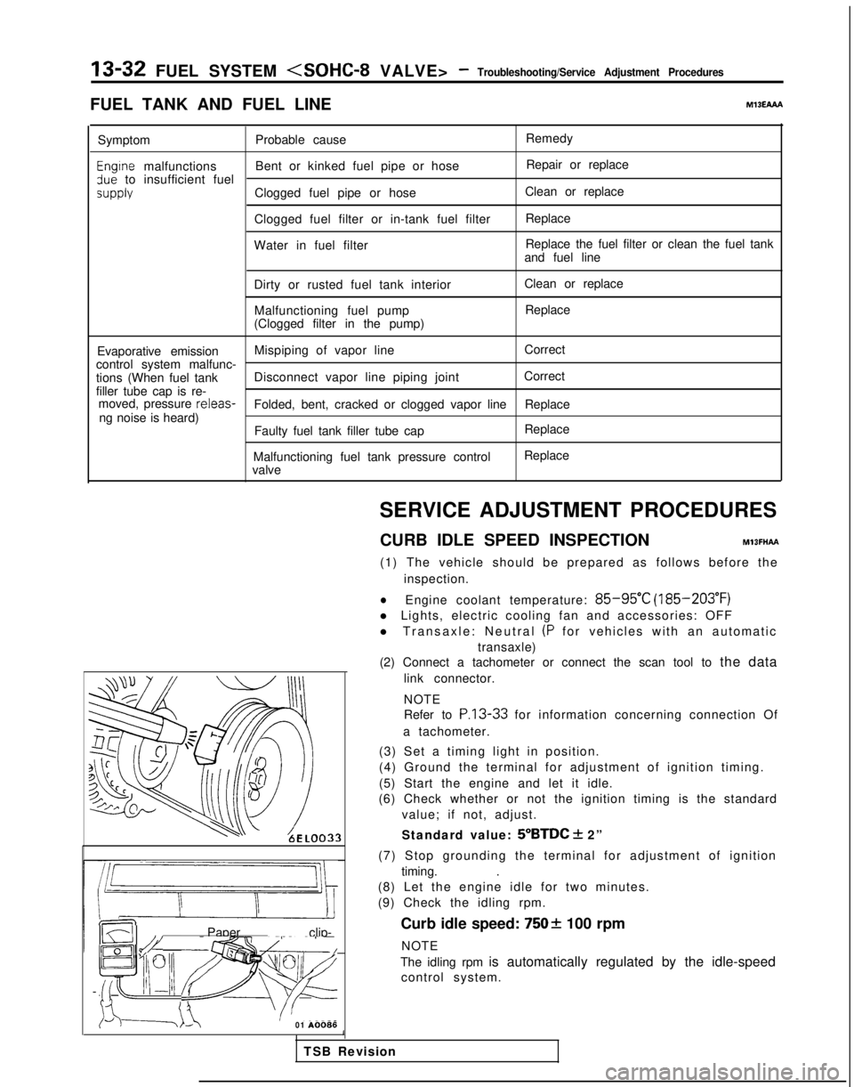
A0086SERVICE ADJUSTMENT PROCEDURES
CURB IDLE SPEED INSPECTION
MlBFHAFt
(1) The vehicle should be prepared as follows before the inspection.
lEngine coolant temperature: 85-95°C (185-203°F)
l Lights, electric cooling fan and accessories: OFF
l Transaxle: Neutral
(P for vehicles with an automatic
transaxle)
(2) Connect a tachometer or connect the scan tool to the data
link connector.
NOTE
Refer to
P.13-33 for information concerning connection Of
a tachometer.
(3) Set a timing light in position.
(4) Ground the terminal for adjustment of ignition timing.
(5) Start the engine and let it idle.
(6) Check whether or not the ignition timing is the standard
value; if not, adjust.
Standard value:
5”BTDC + 2”
(7) Stop grounding the terminal for adjustment of ignition timing. .
(8) Let the engine idle for two minutes.
(9) Check the idling rpm.
Curb idle speed:
7502 100 rpm
NOTE
The idling rpm is automatically regulated by the idle-speed control system.
1
TSB Revision
Page 275 of 1273
FUEL SYSTEM
FUEL TANK AND FUEL LINEMIBEAAB
Symptom
Probable cause Remedy
Engine malfunctions
due to insufficient
fuel supply Bent or kinked fuel pipe or hose
Clogged fuel pipe or hose
Clogged fuel filter or in-tank fuel filter
Water in fuel filter Repair or replace
Clean or replace
Replace
Replace the fuel filter or clean the
fuel tank and fuel line
Dirty or rusted fuel tank interior
Clean or replace
Malfunctioning fuel pump
(Clogged filter in the pump)Replace
Evaporative emission
control system
malfunctions
[When fuel tank filler
tube cap is removed,
pressure releasingnoise is heard) Mispiping of vapor line
Disconnected vapor line piping joint
Folded, bent, cracked or clogged vapor line
Faulty fuel tank filler tube cap
Malfunctioning fuel tank pressure control valve Correct
Correct
Replace
Replace
Replace
SERVICE ADJUSTMENT
PROCEDURES
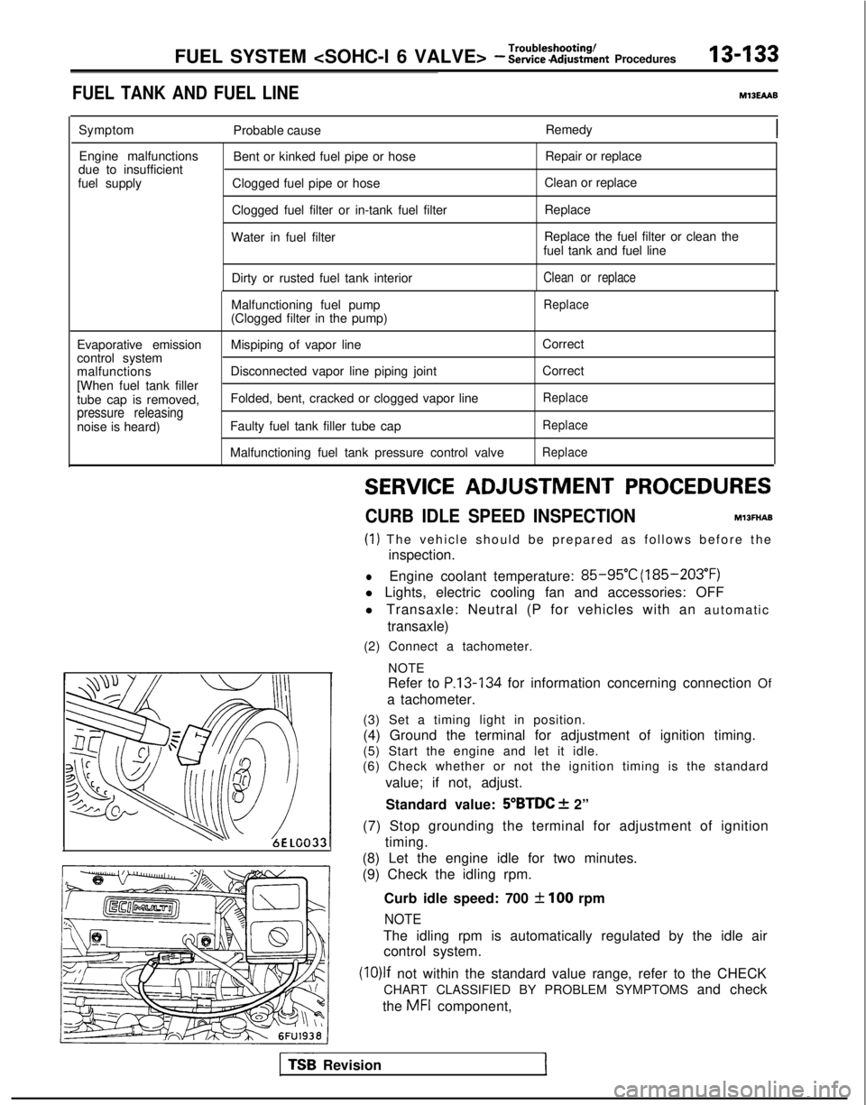
CURB IDLE SPEED INSPECTIONhll3MAE
(1) The vehicle should be prepared as follows before th
e
inspection.
lEngine coolant temperature: 85-95°C (185-203°F)
l Lights, electric cooling fan and accessories: OFF
l Transaxle: Neutral (P for vehicles with an automatic
transaxle)
(2) Connect a tachometer.
NOTE
Refer to
P.13-134 for information concerning connection Of
a tachometer.
(3) Set a timing light in position.
(4) Ground the terminal for adjustment of ignition timing.
(5) Start the engine and let it idle.
(6) Check whether or not the ignition timing is the standard
value; if not, adjust.
Standard value:
5”BTDC f 2”
(7) Stop grounding the terminal for adjustment of ignition timing.
(8) Let the engine idle for two minutes.
(9) Check the idling rpm.
Curb idle speed: 700
31100 rpm
NOTE
The idling rpm is automatically regulated by the idle aircontrol system.
(lO)lf not within the standard value range, refer to the CHECK
CHART CLASSIFIED BY PROBLEM SYMPTOMS and check
the
MFI component,
TS6 Revision1
Page 386 of 1273
13-244FUEL SYSTEM
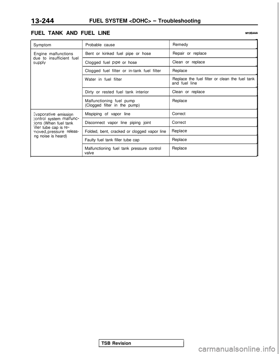
FUEL TANK AND FUEL LINE
MlBEAAh
Symptom Probable cause Remedy
Engine malfunctions Bent or kinked fuel pipe or hose Repair or replace
due to insufficient fuel supply
Clogged fuel pipe
or hose Clean or replace
Clogged fuel filter or in-tank fuel filter Replace
Water in fuel filter Replace the fuel filter or clean the fuel tank
and fuel line
Dirty or rested fuel tank interior
Malfunctioning fuel pump
(Clogged filter in the pump) Clean or replace
Replace Zvaporative
emission Mispiping of vapor line
Correct
:ontrol system malfunc-:ions (When fuel tank
Disconnect vapor line piping joint
Correct‘iller tube cap is re-noved, pressure releas-
Folded, bent, cracked or clogged vapor lineReplaceng noise is heard)
Faulty fuel tank filler tube cap
Malfunctioning fuel tank pressure control
valve Replace
Replace
TSB Revision
I
Page 553 of 1273
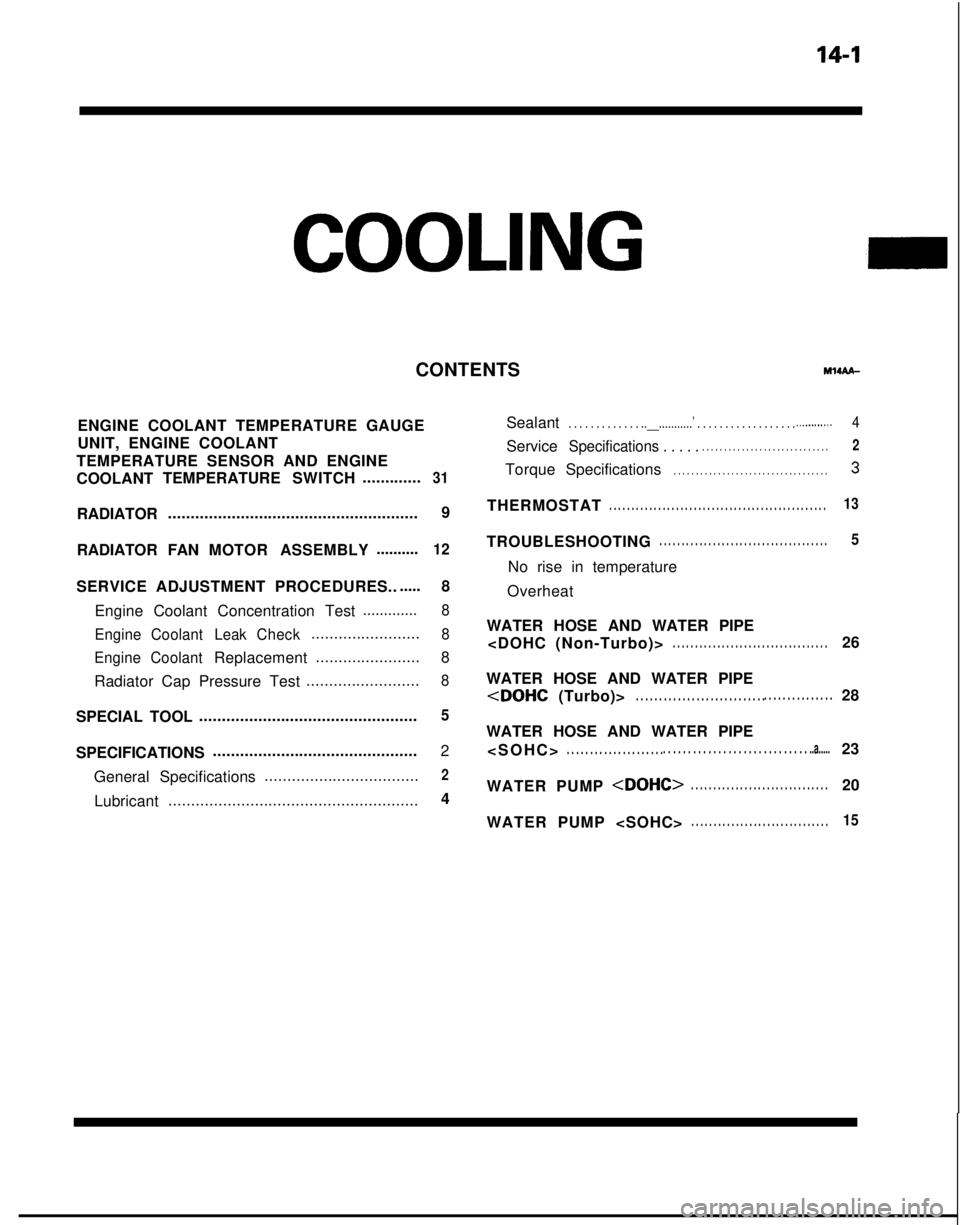
14-1
COOLING
ENGINE COOLANT TEMPERATURE GAUGE
UNIT, ENGINE COOLANT
TEMPERATURE SENSOR AND ENGINE
COOLANT TEMPERATURE
SWITCH.............
31
RADIATOR ....................................................... 9
RADIATOR FAN MOTOR ASSEMBLY ..........
12
SERVICE ADJUSTMENT PROCEDURES..
.....
8
Engine Coolant Concentration Test .............
8
Engine Coolant LeakCheck
........................8
Engine Coolant
Replacement .......................
8
Radiator Cap Pressure Test .........................
8
SPECIAL TOOL................................................5
SPECIFICATIONS .............................................
2
General Specifications ..................................
2
Lubricant
....................................................... 4
CONTENTS
IM14AA-
Sealant. . . . . . . . . . . . . ..__...........’ . . . . . . . . . . . . . \
. . . . . .._.........4
ServiceSpecifications . . . . .. . . . . . . . . . . . . . . . . . . . . . . . . . . . .2
Torque
Specifications. . . . . . . . . . . . . . . . . . . . . . . . . . . . . . . . . . .3
THERMOSTAT. . . . . . . . . . . . . . . . . . . . . . . . . . . . . . . . . . . . \
. . . . . . . . . . . . .13
TROUBLESHOOTING. . . . . . . . . . . . . . . . . . . . . . . . . . . . . . . . . . . . \
. .5
No rise in temperature
Overheat
WATER HOSE AND WATER PIPE
. . . . . . . . . . . . . . . . . . . . . . . . . . . . . . . . . . .26
WATER HOSE AND WATER PIPE
WATER HOSE AND WATER PIPE
. . . . . . . . . . . . . . . . . . . . .
. . . . . . . . . . . . . . . . . . . . . . . . . . . . . ..a.....23
WATER PUMP
WATER PUMP
. . . . . . . . . . . . . . . . . . . . . . . . . . . . . . .15
Page 554 of 1273
14-2
COOLING- Specifications
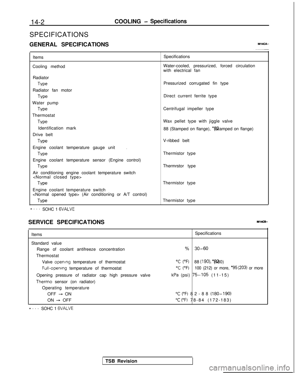
SPECIFICATIONS
GENERAL SPECIFICATIONS
MlICA-
Items
Cooling method Specifications
Water-cooled, pressurized, forced circulation
with electrical fan
Radiator Type
Radiator fan motor Type
Water pump Type
Thermostat Type
Identification mark
Drive belt Type
.Engine coolant temperature gauge unit
Type
Engine coolant temperature sensor (Engine control) Type
Air conditioning engine coolant temperature switch
Engine coolant temperature switch
* . . .SOHC 1 GVALVE
Pressurized corrugated fin type
Direct current ferrite type
Centrifugal impeller type
Wax pellet type with jiggle valve 88 (Stamped on flange), *82 (Stamped on flange)
V-ribbed belt
Thermistor type
Thermrstor type
Thermistor type
Thermistor type
SERVICE SPECIFICATIONS
MlOCB-
Items
Standard value Range of coolant antifreeze concentration
Thermostat Valve opening
temperature of thermostat Full-opening
temperature of thermostat
Opening pressure of radiator cap high pressure valve Therm0
sensor (on radiator)
Operating temperature OFF
+ ON
ON
+ OFF
* . . .SOHC 1 GVALVE
Specifications
% 30-60
“C (“F)88 (IgO), *82 (180)
T (OF)100 (212) or more, *95 (203) or more
kPa (psi) 75-105 (11-15
)
“C (“F) 82-88 (180-190)
“C (“F) 78-84 (172-183
)
TSB Revision
Page 555 of 1273
COOLING- Specifications14-3
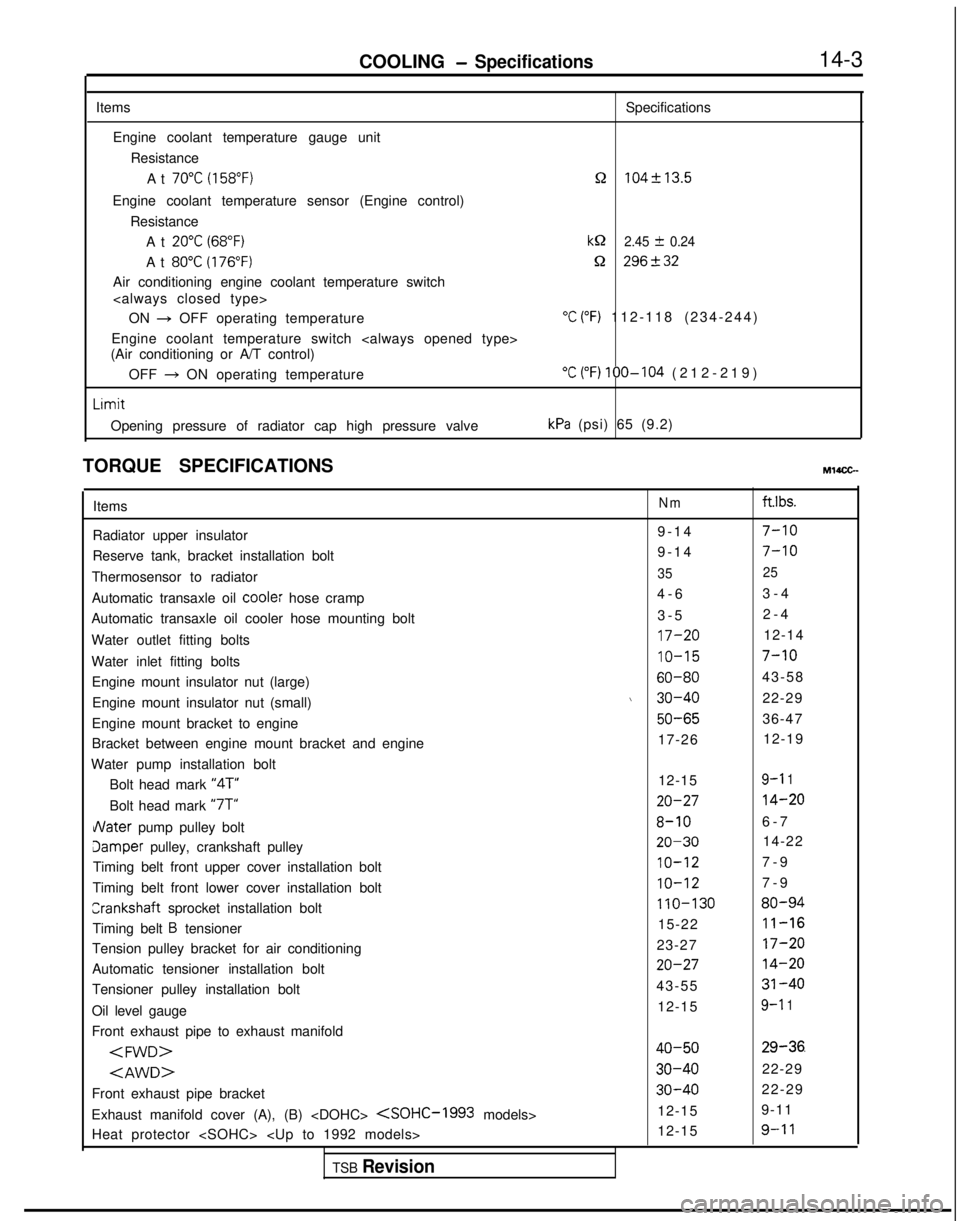
Items Specifications
Engine coolant temperature gauge unit ResistanceAt
70°C (158°F)n 104f13.5
Engine coolant temperature sensor (Engine control) ResistanceAt
20°C (68°F)kQ 2.45 f 0.24
At 80°C (176°F)Q 296+32
Air conditioning engine coolant temperature switch
ON
+ OFF operating temperature“C (“F) 112-118 (234-244
)
Engine coolant temperature switch
(Air conditioning or A/T control)
OFF
+ ON operating temperature“C (“F) 100-104 (212-219
)
Limit
Opening pressure of radiator cap high pressure valvekPa (psi) 65 (9.2)
TORQUE SPECIFICATIONS
MWCG-
ItemsNm ft.lbs.
Radiator upper insulator 9-14
7-10
Reserve tank, bracket installation bolt9-1
4
7-10
Thermosensor to radiator35
25
Automatic transaxle oil coole: hose cramp 4-
6
3-4
Automatic transaxle oil cooler hose mounting bolt 3-5
2-4
Water outlet fitting bolts
17-2012-14
Water inlet fitting bolts
IO-157-10
Engine mount insulator nut (large)60-8043-58
Engine mount insulator nut (small)
\ 30-4022-29
Engine mount bracket to engine
50-6536-47
Bracket between engine mount bracket and engine 17-26
12-19
Water pump installation bolt Bolt head mark “4T”
12-15
9-l 1
Bolt head mark “7T”20-2714-20
dater pump pulley bolt8-106-
7
Jamper pulley, crankshaft pulley20-3014-22
Timing belt front upper cover installation bolt
IO-127-
9
Timing belt front lower cover installation bolt
IO-127-
9
Crankshaft
sprocket installation bolt
110-13080-94
Timing belt B tensioner 15-2211-16
Tension pulley bracket for air conditioning
23-2717-20
Automatic tensioner installation bolt20-2714-20
Tensioner pulley installation bolt43-5531-40
Oil level gauge 12-159-l 1
Front exhaust pipe to exhaust manifold
Front exhaust pipe bracket
30-4022-29
Exhaust manifold cover (A), (B)
9-11
Heat protector
TSB Revision
Page 557 of 1273
COOLING - Special TooVTroubleshooting
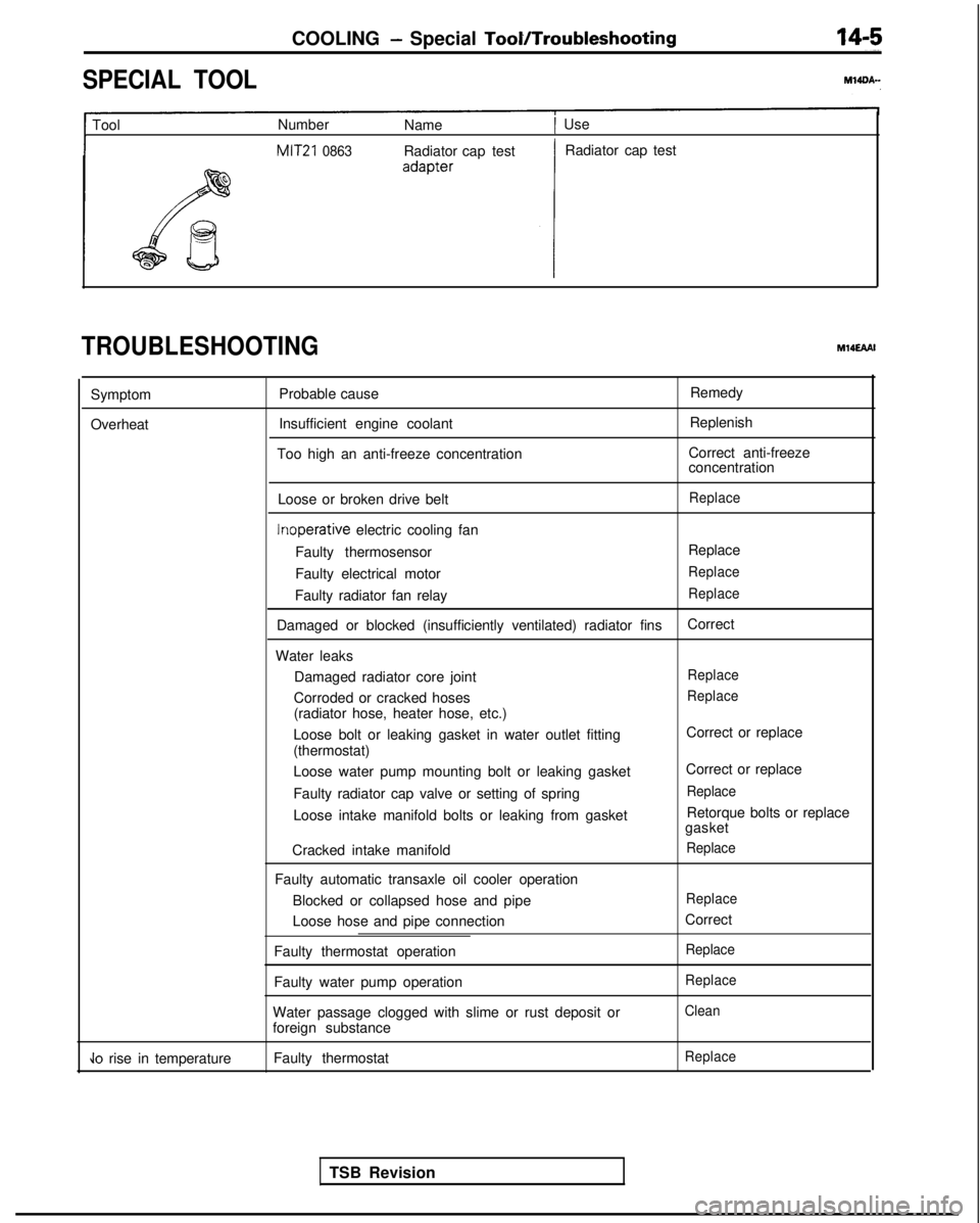
SPECIAL TOOL
1 Tool
Number
Name1 Use
MIT21 0863Radiator cap test Radiator cap test
TROUBLESHOOTINGM14EAAI
Symptom
Overheat Probable cause
Insufficient engine coolant
Too high an anti-freeze concentration Remedy
Replenish
Correct anti-freeze
concentration
Loose or broken drive belt
Replace Inoperative
electric cooling fan
Faulty thermosensor Replace
Faulty electrical motor
Replace
Faulty radiator fan relayReplace
Damaged or blocked (insufficiently ventilated) radiator fins Correct
Water leaks Damaged radiator core joint
Replace
Corroded or cracked hosesReplace
(radiator hose, heater hose, etc.)
Loose bolt or leaking gasket in water outlet fitting
(thermostat)
Loose water pump mounting bolt or leaking gasket
Faulty radiator cap valve or setting of spring
Loose intake manifold bolts or leaking from gasket
Cracked intake manifold
Faulty automatic transaxle oil cooler operation Blocked or collapsed hose and pipe
Loose hose and pipe connection
Faulty thermostat operation
Faulty water pump operation
Water passage clogged with slime or rust deposit or
foreign substance Correct or replace
Correct or replace
Replace
Retorque bolts or replace
gasket
Replace
Replace
Correct
Replace
Replace
Clean
Jo rise in temperature Faulty thermostatReplace
TSB Revision
Page 567 of 1273
COOLING - Water Pump
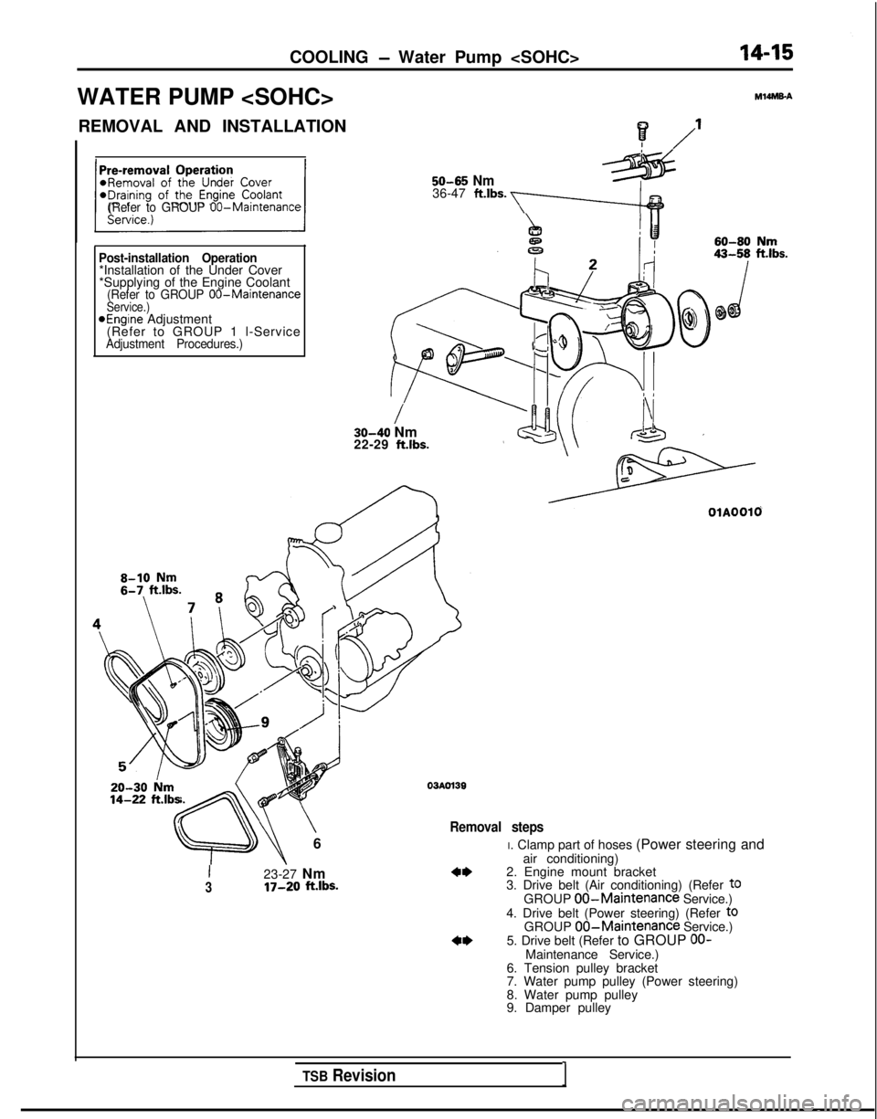
WATER PUMP
M14MEA
? /’I
50-65 Nm36-47 ft.lbs. a(Refer to GROUP 00-Maintenance
Post-installation Operation*Installation of the Under Cover
*Supplying of the Engine Coolant
(Refer to GROUP 00-MaintenanceService.)aEngine Adjustment
(Refer to GROUP 1 l-Service
Adjustment Procedures.)
/30-40 Nm
22-29 ft.lbs. 14-22
ft.lb=
\
6
03AOl39
Removal steps
I23-27 Nm3IT-20 ft.lbs.
OlAOOlO
I. Clamp part of hoses (Power steering and
air conditioning)
2. Engine mount bracket
3. Drive belt (Air conditioning) (Refer
t0GROUP 00-Maintenance Service.)
4. Drive belt (Power steering) (Refer toGROUP 00-Maintenance Service.)
5. Drive belt (Refer to GROUP OO-Maintenance Service.)
6. Tension pulley bracket
7. Water pump pulley (Power steering)
8. Water pump pulley
9. Damper pulley
TSB Revision1
Page 568 of 1273
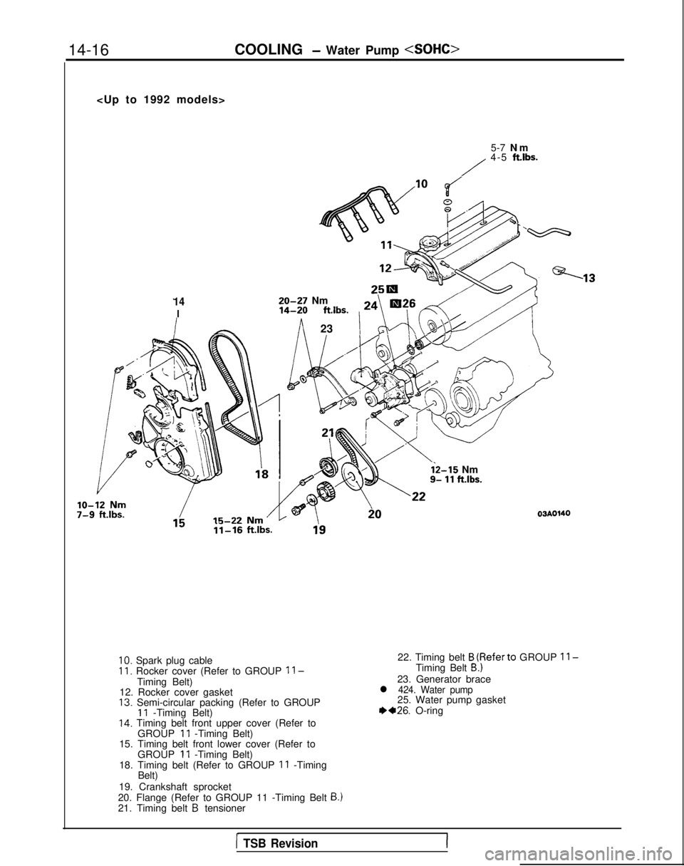
14-16
COOLING - Water Pump
5-7 N
m
/
4-5
ftlbs.
1420-27 Nm
I14-20
ftlbs.
24 ’
\ ‘G\@;&
\“7”f=-is .
In23
ii-16 ftlbs.
i2-15 Nm9- 11 ft.lbs.
03AOWO
10. Spark plug cableII. Rocker cover (Refer to GROUP ll-Timing Belt)
12. Rocker cover gasket
13. Semi-circular packing (Refer to GROUP11 -Timing Belt)14. Timing belt front upper cover (Refer to
GROUP 11 -Timing Belt) 22. Timing belt
B (Referto GROUP ll-Timing Belt B.)
23. Generator bracel 424. Water pump25. Water pump gasket 1)+26.
O-ring
15. Timing belt front lower cover (Refer to GROUP
11 -Timing Belt)
18. Timing belt (Refer to GROUP 11 -Timing
Belt)
19. Crankshaft sprocket
20. Flange (Refer to GROUP 11 -Timing Belt
B.)21. Timing belt B tensioner
1 TSB Revision
Page 569 of 1273

COOLING - Water Pump
10-7-
9
Cl993 models>
43-55 Nm31-40 ftlbs.
\
20-27 Nm14-20 ftlbs.
3-3.5 NmI
2.2-2.5 ftlbs.
y
12 Nm ftlbs.
i,4-2Oft.l;~
Nrn’x@<,I 1-16 ft.lbs.,
OlAO675
I110-130 Nm80-94 ft.lbs.
11. Rocker cover (Refer to GROUP
11 -Timing Belt.)
12. Rocker cover gasket
14. Timing belt front upper cover (Refer to
GROUP
11 -Timing Belt.)
15. Timing belt front lower cover (Refer to GROUP
11 -Timing Belt.)
16. Automatic tensioner (Refer to GROUP
11 -Timing Belt.)17. Tension pulley
18. Timing belt (Refer to GROUP 11 -Timing
Belt.)
20. Flange (Refer to GROUP 11 -Timing Belt
B.121. Timing belt B tensioner22. Timing belt B (Refer to GROUP11 -Timing Belt B.)23. Generator brace+424. Water pump
25. Water pump gasket
++26. O-ring
19. Crankshaft sprocket
1 TSB Revision