MITSUBISHI GALANT 1989 Service Repair Manual
Manufacturer: MITSUBISHI, Model Year: 1989, Model line: GALANT, Model: MITSUBISHI GALANT 1989Pages: 1273, PDF Size: 37.62 MB
Page 381 of 1273
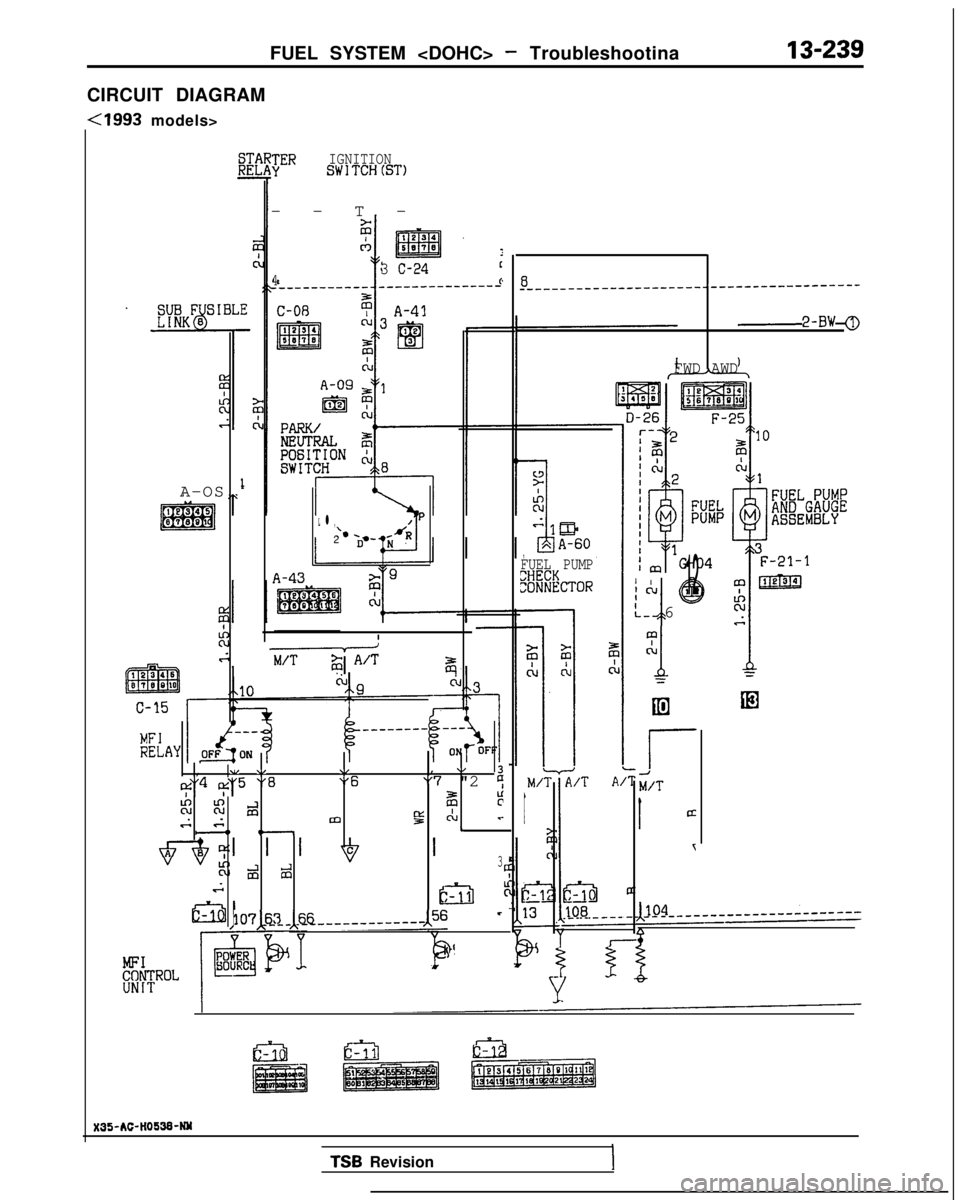
FUEL SYSTEM
CIRCUIT DIAGRAM
-Cl993 models>
A-OS
JER IGNITIONSWlTCH(ST)
--T
-
3 C-24c
4c
L l ,P
‘*2
A-43
+$1 A’Tz
, .I \/\,, \/3
I$'4 $'5 "8"6"7 "2 9
%Ki dF;rv,. 84m!z C-kJLc--o e-
d 23
2
107x~~-~~~______-------,56 -
I
&ROL
8_-____-___-_-__--___---------------------
2-BW
FWD AWD
FUEL PUMP
%#cT~RI I!”
J
@12
k. 6
m
cl
1
;
r
M/T
1ci
T
X35-AC-HO!i3&NM
TSB
Revision
Page 382 of 1273
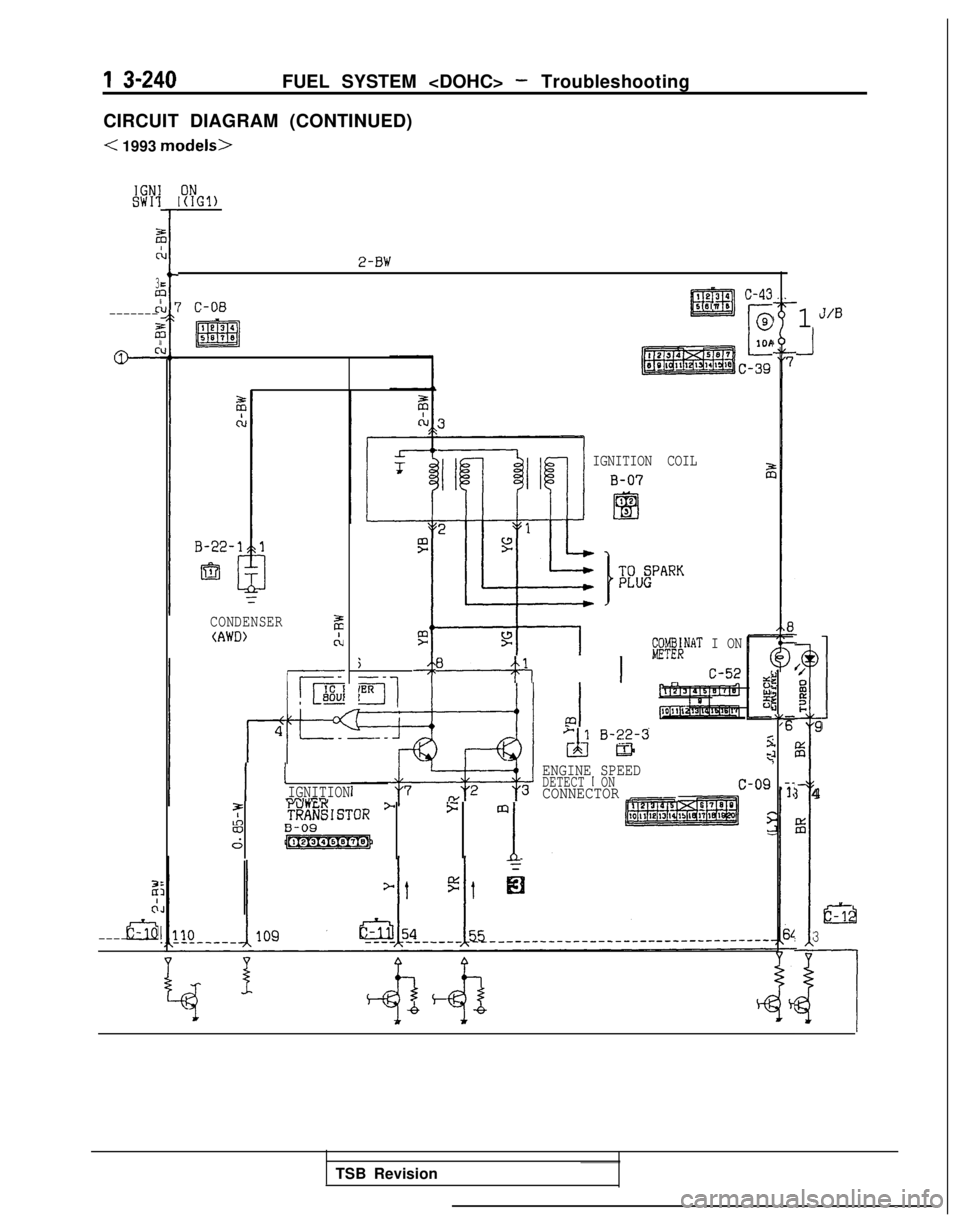
1 S-240FUEL SYSTEM
CIRCUIT DIAGRAM (CONTINUED)
< 1993 models>
IGNISW11
2
C
30
z’-------
2
ci+
21
&--------
I?YGl)
2-BW
7 C-08
1134
m5870
CONDENSERz(AWD)ct
j--
IER11
I ’IGNITIONnn3IIPl-,
I e3 4 c-43
ED507 5
C
@
1011
c-39
IGNITION COIL
iFZ;NAT I ON
w, 1 C-52
&) B-g-3
ENGINE SPEEDDETECT I ONCONNECTOR Irl
j:5 m
83B-09
61
4;5ALI.
i,
,
1J/B
J
‘/0i?0I-]9
%
~
I 4
iz
:I
liEA
3
u
TSB Revision
Page 383 of 1273
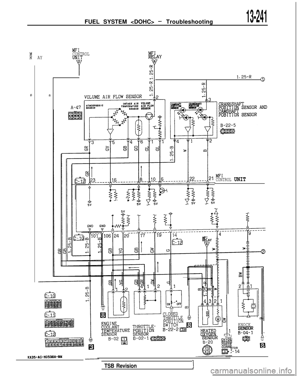
FUEL SYSTEM
MFICONTROLl&Y
lxlAcu.-i1.25-R0
AY
a
A-47
MFI
CONTROL UNIT
!z
&%R l.Tl
KNOCK
,"";y
I lg@l 42
CTOREl
2-14
TSB Revision1
KX35-AC-lt0536kNY
Page 384 of 1273
![MITSUBISHI GALANT 1989 Service Repair Manual 13-242FUEL SYSTEM <DOHC> - Troubleshooting
CIRCUIT DIAGRAM (CONTINUED)
< 1993 models>
sA-OB-
I
6
T
POWERSTEERINGgpX&RE
J/l3
\,\I4c-3
m
clLl
;
z
~~+l~:&--
*.z 3.
110+ v]
(CNG) (DATA
)
C- 18EFRONT SIDE MITSUBISHI GALANT 1989 Service Repair Manual 13-242FUEL SYSTEM <DOHC> - Troubleshooting
CIRCUIT DIAGRAM (CONTINUED)
< 1993 models>
sA-OB-
I
6
T
POWERSTEERINGgpX&RE
J/l3
\,\I4c-3
m
clLl
;
z
~~+l~:&--
*.z 3.
110+ v]
(CNG) (DATA
)
C- 18EFRONT SIDE](/img/19/57312/w960_57312-383.png)
13-242FUEL SYSTEM
CIRCUIT DIAGRAM (CONTINUED)
< 1993 models>
sA-OB-
I
6
T
POWERSTEERINGgpX&RE
J/l3
\,\I4c-3
m
clLl
;
z
~~+l~:&--
*.z 3.
110+ v]
(CNG) (DATA
)
C- 18EFRONT SIDE
5V
I
4%_-__-_-_________-----.--
11
r
12g 15g%
1
2
i
F
1
IGNITION
TIMING ADJUSTMENT
CONNECTOR
1
II
E
2 1
2
A-61
ml
%ES&$MERATURE
WEHI CLES FORCALIFORNIA)
E-04
Igig .
TROLP(AWD>
1 TSB RevisionI
Page 385 of 1273
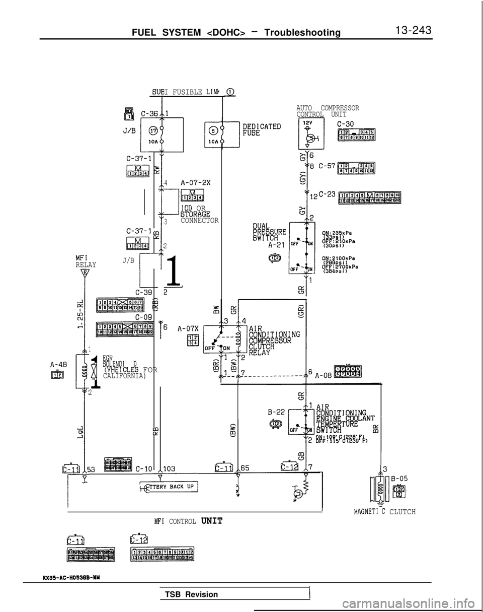
FUEL SYSTEM
13-243
A-48
IEEl
Sl-
c-37-3,:
l&l
lx
1e34
MFIRELAYJ/Br
1
1
x
BSLHENOI D(VHEICLES FORCALIFORNIA)
2
&
53c-10
-
103
, BAWL”‘,
E2-J
G
I FUSIBLE LINb
C
0
10A
4A-07-2X
1
liizEa1234
IOD ORGTORAGE3CONNECTOR
2
1
2
AUTO COMPRESSOR
CONTROL UNIT
OF? N
i
!
%
#j;;y;,
(3OPSl)
0N:ZlOOhPa(29DPSi)OFF:2’i’OOkPa(384PS I)
I
[
MAGNET1 C CLUTCH
3
lh
B-05
Elle.3
=
MFI CONTROL UNIT
TSB Revision
Page 386 of 1273
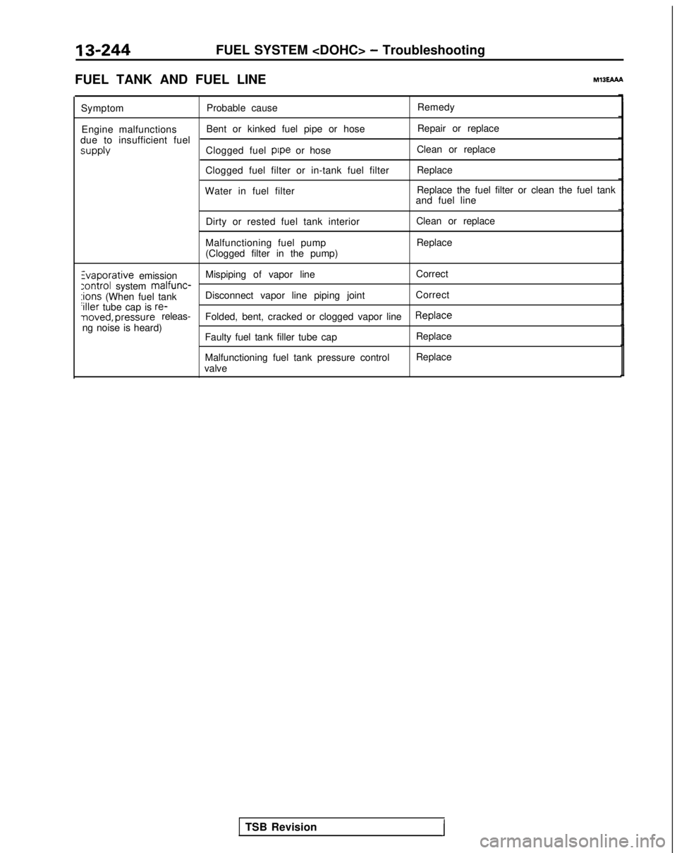
13-244FUEL SYSTEM
FUEL TANK AND FUEL LINE
MlBEAAh
Symptom Probable cause Remedy
Engine malfunctions Bent or kinked fuel pipe or hose Repair or replace
due to insufficient fuel supply
Clogged fuel pipe
or hose Clean or replace
Clogged fuel filter or in-tank fuel filter Replace
Water in fuel filter Replace the fuel filter or clean the fuel tank
and fuel line
Dirty or rested fuel tank interior
Malfunctioning fuel pump
(Clogged filter in the pump) Clean or replace
Replace Zvaporative
emission Mispiping of vapor line
Correct
:ontrol system malfunc-:ions (When fuel tank
Disconnect vapor line piping joint
Correct‘iller tube cap is re-noved, pressure releas-
Folded, bent, cracked or clogged vapor lineReplaceng noise is heard)
Faulty fuel tank filler tube cap
Malfunctioning fuel tank pressure control
valve Replace
Replace
TSB Revision
I
Page 387 of 1273
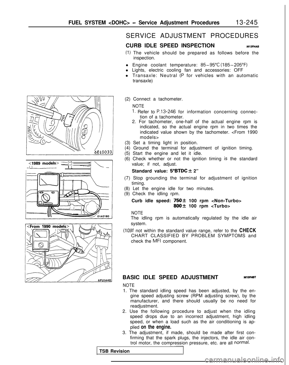
FUEL SYSTEM
cl989 models> -a’i\.-upI t
SERVICE ADJUSTMENT PROCEDURES
CURB IDLE SPEED INSPECTION
MlSFHAB
(1) The vehicle should be prepared as follows before the inspection.
l Engine coolant temperature:
85-95°C (185-205°F)
l Lights, electric cooling fan and accessories: OFF
l Transaxle: Neutral
(P for vehicles with an automatic
transaxle)
(2) Connect a tachometer.
NOTE
1. Refer to P.13-246 for information concerning connec-
tion of a tachometer.
2. For tachometer, one-half of the actual engine rpm is
indicated, so the actual engine rpm in two times the
indicated value shown by the tachometer.
(3) Set a timing light in position.
(4) Ground the terminal for adjustment of ignition timing.
(5) Start the engine and let it idle.
(6) Check whether or not the ignition timing
is the standard
value; if not, adjust.
Standard value:
5”BTDC f 2”
(7) Stop grounding the terminal for adjustment of ignition timing.
(8) Let the engine idle for two minutes.
(9) Check the idling rpm.
Curb idle speed:
75Ok 100 rpm
800+ 100 rpm
NOTE
The idling rpm is automatically regulated by the idle airsystem.
(10)lf not within the standard value range, refer to the CHECK
CHART CLASSIFIED BY PROBLEM SYMPTOMS and
check the
MFI component.
BASIC IDLE SPEED ADJUSTMENT
Ml3FHBl
NOTE
1. The standard idling speed has been adjusted, by the en- gine speed adjusting screw (RPM adjusting screw), by the
manufacturer, and there should usually be no need for
readjustment.
2. Use the following procedure to adjust when the idling speed drops due to an incorrect adjustment, high idling
speed, or when a load such as the air conditioning is ap-
plied on the engine.
3. The adjustment, if made, should be made after first con- firming that the spark plugs, the injectors, the idle air con-trol motor, the compression pressure, etc. are all
normal.~~-
TSB Revision
Page 388 of 1273
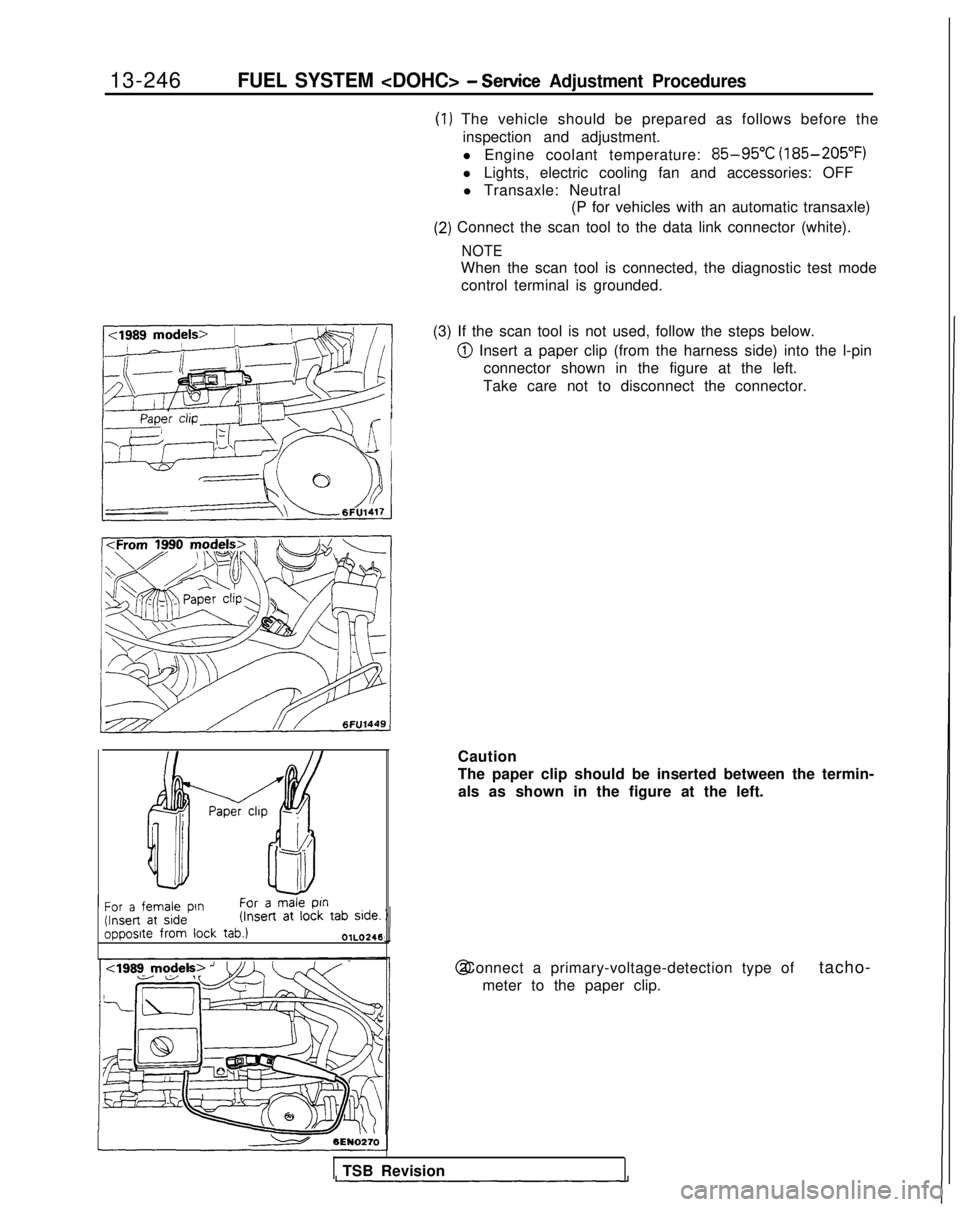
13-246FUEL SYSTEM
17k&---,!E~,~~/iY I
(1) The vehicle should be prepared as follows before the
inspection and adjustment.
l Engine coolant temperature:
85-95°C (185-205°F)
l Lights, electric cooling fan and accessories: OFF l Transaxle: Neutral (P for vehicles with an automatic transaxle)
(2) Connect the scan tool to the data link connector (white).
NOTE
When the scan tool is connected, the diagnostic test mode
control terminal is grounded.
(3) If the scan tool is not used, follow the steps below.
@ Insert a paper clip (from the harness side) into the l-pin connector shown in the figure at the left.
Take care not to disconnect the connector.
/ Paper chp -
f!f--i!t
Ah
-II
For a female pin
For a male
ptn (Insert
at side (Insert
at
lock tab side.
opposite from
lock
tab.)OlL0246
Caution
The paper clip should be inserted between the termin-
als as shown in the figure at the left. @ Connect a primary-voltage-detection type of
tacho-
meter to the paper clip.
TSB Revision
Page 389 of 1273
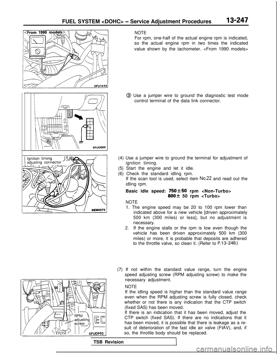
FUEL SYSTEM
NOTE
For rpm, one-half of the actual engine rpm is indicated,
so the actual engine rpm in two times the indicated
value shown by the tachometer.
@I Use a jumper wire to ground the diagnostic test mode control terminal of the data link connector.
(4) Use a jumper wire to ground the terminal for adjustment of ignition timing.
(5) Start the engine and let it idle.
(6) Check the standard idling rpm. If the scan tool is used, select item
No.22 and read out the
idling rpm.
Basic idle speed:
750+50 rpm
800f 50 rpm
NOTE
1. The engine speed may be 20 to 100 rpm lower than indicated above for a new vehicle [driven approximately
500 km (300 miles) or less], but no adjustment is
necessary.
2.If the engine stalls or the rpm is low even though the
vehicle has been driven approximately 500 km (300
miles) or more, it is probable that deposits are adhered
to the throttle valve, so clean it. (Refer to P.13-248.)
TSB Revision
1
(7) If not within the standard value range, turn the engine speed adjusting screw (RPM adjusting screw) to make thenecessary adjustment.
NOTE
If the idling speed is higher than the standard value range
even when the RPM adjusting screw is fully closed, check
whether or not there is any indication that the CTP switch
(fixed SAS) has been moved.
If there is an indication that it has been moved, adjust the
CTP switch (fixed SAS). If there are no indications that it has been moved, it is possible that there is leakage as a re-
sult of deterioration of the fast idle air valve (FIAV), and, if
so, the throttle body should be replaced.
Page 390 of 1273
13-248FUEL SYSTEM
(8) Switch OFF the ignition switch.
(9) If the scan tool was not used, disconnect the jumper wire from the diagnostic test mode control terminal. (10)Disconnect
the jumper wire from the terminal for adjust-
ment of ignition timing, and return the connector to its
original condition.
(11
)Start the engine again and let it run at idle speed for about
ten minutes; check to be sure that the idling condition is
normal.
THROTTLE BODY (THROTTLE VALVE AREA)
CLEANING
Ml3ACL
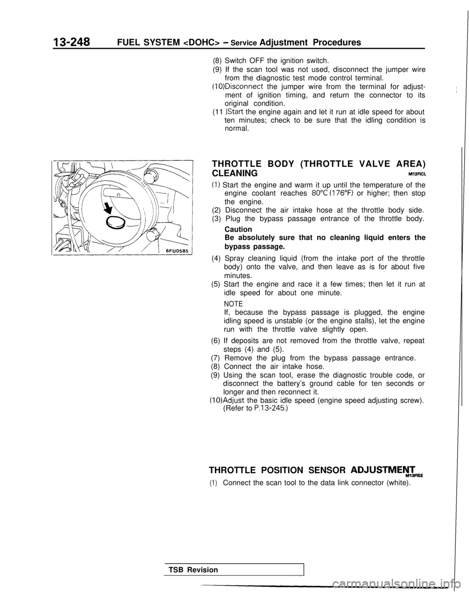
(1) Start the engine and warm it up until the temperature of the engine coolant reaches
80°C (176°F) or higher; then stop
the engine.
(2) Disconnect the air intake hose at the throttle body side.
(3) Plug the bypass passage entrance of the throttle body.
Caution
Be absolutely sure that no cleaning liquid enters the
bypass passage.
(4) Spray cleaning liquid (from the intake port of the throttle body) onto the valve, and then leave as is for about five
minutes.
(5) Start the engine and race it a few times; then let it run at
idle speed for about one minute.
NOTE
If, because the bypass passage is plugged, the engine
idling speed is unstable (or the engine stalls), let the engine
run with the throttle valve slightly open.
(6) If deposits are not removed from the throttle valve, repeat steps (4) and (5).
(7) Remove the plug from the bypass passage entrance.
(8) Connect the air intake hose.
(9) Using the scan tool, erase the diagnostic trouble code, or disconnect the battery’s ground cable for ten seconds or
longer and then reconnect it. (lO)Adjust
the basic idle speed (engine speed adjusting screw).
(Refer to
P.13-245.)
THROTTLE POSITION SENSOR ADJUSTMEyTmEE
(1)Connect the scan tool to the data link connector (white).
TSB Revision