engine coolant MITSUBISHI GALANT 1989 Service Repair Manual
[x] Cancel search | Manufacturer: MITSUBISHI, Model Year: 1989, Model line: GALANT, Model: MITSUBISHI GALANT 1989Pages: 1273, PDF Size: 37.62 MB
Page 3 of 1273
00-l
GENERAL
CONTENTS
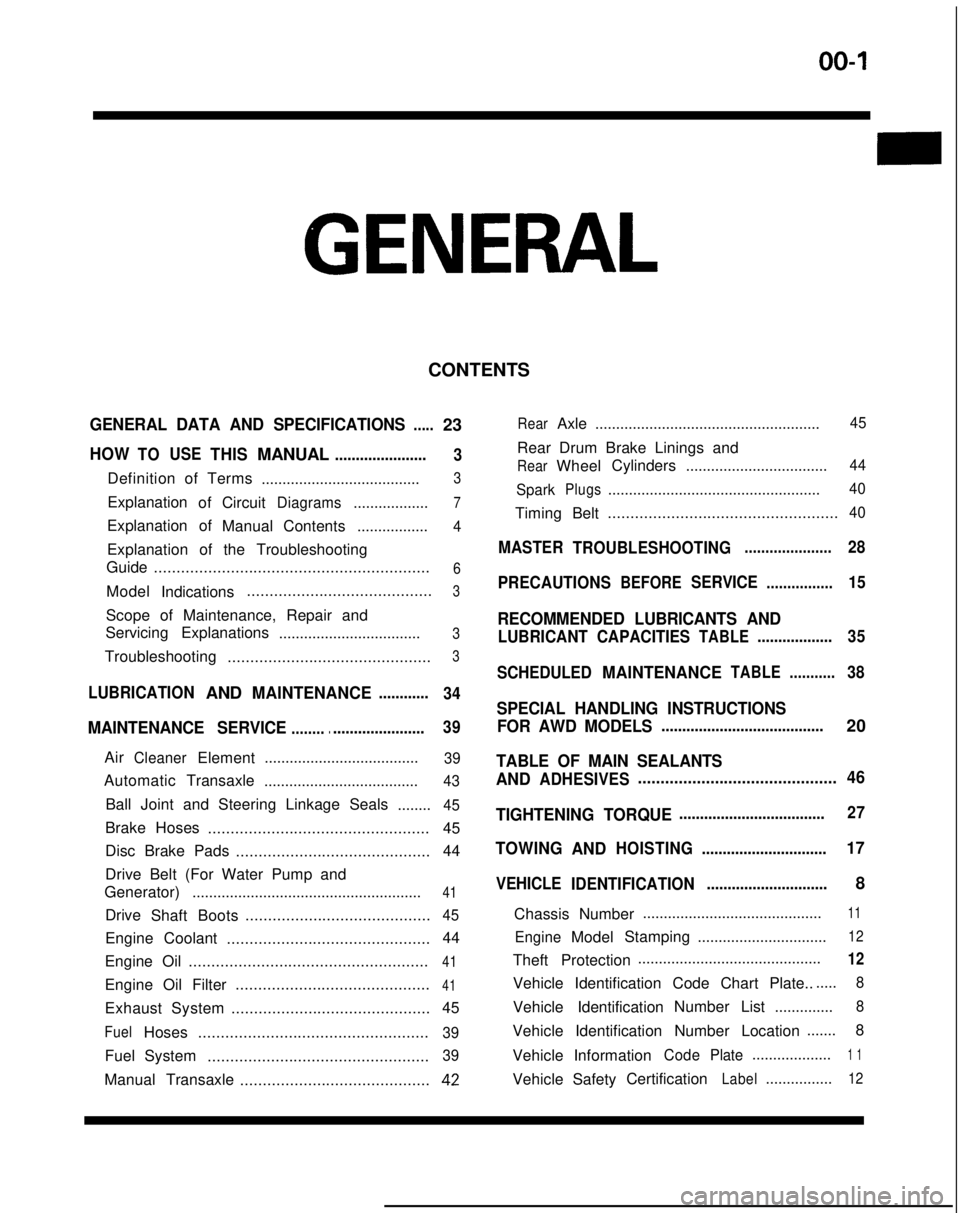
GENERAL DATA AND SPECIFICATIONS.....23
HOWTOUSETHISMANUAL......................
3
Definition of Terms ......................................3
ExplanationofCircuitDiagrams..................7
Explanation of
ManualContents .................4
Explanation of the Troubleshooting
Guide .............................................................
6
Model
Indications .........................................3
Scope of Maintenance, Repair and
Servicing Explanations
..................................
3
Troubleshooting .............................................3
LUBRICATIONANDMAINTENANCE............
34
MAINTENANCE SERVICE............................... 39
AirCleanerElement
.....................................39
Automatic
Transaxle
.....................................43
Ball Joint and Steering Linkage Seals ........45
Brake Hoses................................................. 45
Disc Brake Pads ........................................... 44
Drive Belt (For Water Pump and
Generator) .......................................................
41
Drive
Shaft Boots .........................................45
Engine Coolant
............................................. 44
Engine Oil .....................................................
41
Engine Oil Filter ...........................................41
Exhaust System
............................................ 45
FuelHoses
...................................................39
Fuel System
.................................................39
Manual Transaxle ..........................................42
RearAxle......................................................45
Rear Drum Brake Linings and
RearWheel Cylinders
..................................44
Spark
Plugs...................................................40
Timing Belt...................................................40
MASTER
TROUBLESHOOTING.....................28
PRECAUTIONS
BEFORESERVICE................15
RECOMMENDED LUBRICANTS AND
LUBRICANT CAPACITIESTABLE..................35
SCHEDULED
MAINTENANCETABLE ...........38
SPECIAL HANDLING INSTRUCTIONS
FOR AWD MODELS
.......................................20
TABLE OF MAIN SEALANTS
AND
ADHESIVES ............................................46
TIGHTENING TORQUE
................................... 27
TOWING
ANDHOISTING ..............................17
VEHICLE
IDENTIFICATION .............................8
Chassis Number ...........................................
11
EngineModel
Stamping
...............................12
Theft Protection ............................................12
Vehicle Identification Code Chart Plate.......
8
Vehicle Identification Number List
..............8
Vehicle Identification Number Location .......
8
Vehicle Information
CodePlate...................1 1
Vehicle SafetyCertificationLabel................12
Page 18 of 1273
00-l 6GENERAL - Precautions before Service
Caution
1. Before connecting or disconnecting the negative
cable, be sure to turn off the ignition switch and the
lighting switch.
(If this is not done,there is the possibility of
semiconductor parts being damaged.)
2.For MFI-equipped models, after completion of the
work steps [when the battery’s negative (-) termi-
nal is connected], warm up the engine and allow it
to idle for approximately five minutes under the
conditions described below, in order to stabilize
engine control conditions, and then check to be
sure that the idling is satisfactory.
Engine coolant temperature:
85-95X (185-203°F)
Lights, electric fans, accessories: OFF
Transaxle: neutral position (A/T models: “N” or
“P”)
Steering wheel:neutral (center) position
mm (tn.1
Scan Tool(Multi-use tester
ROM pack
1
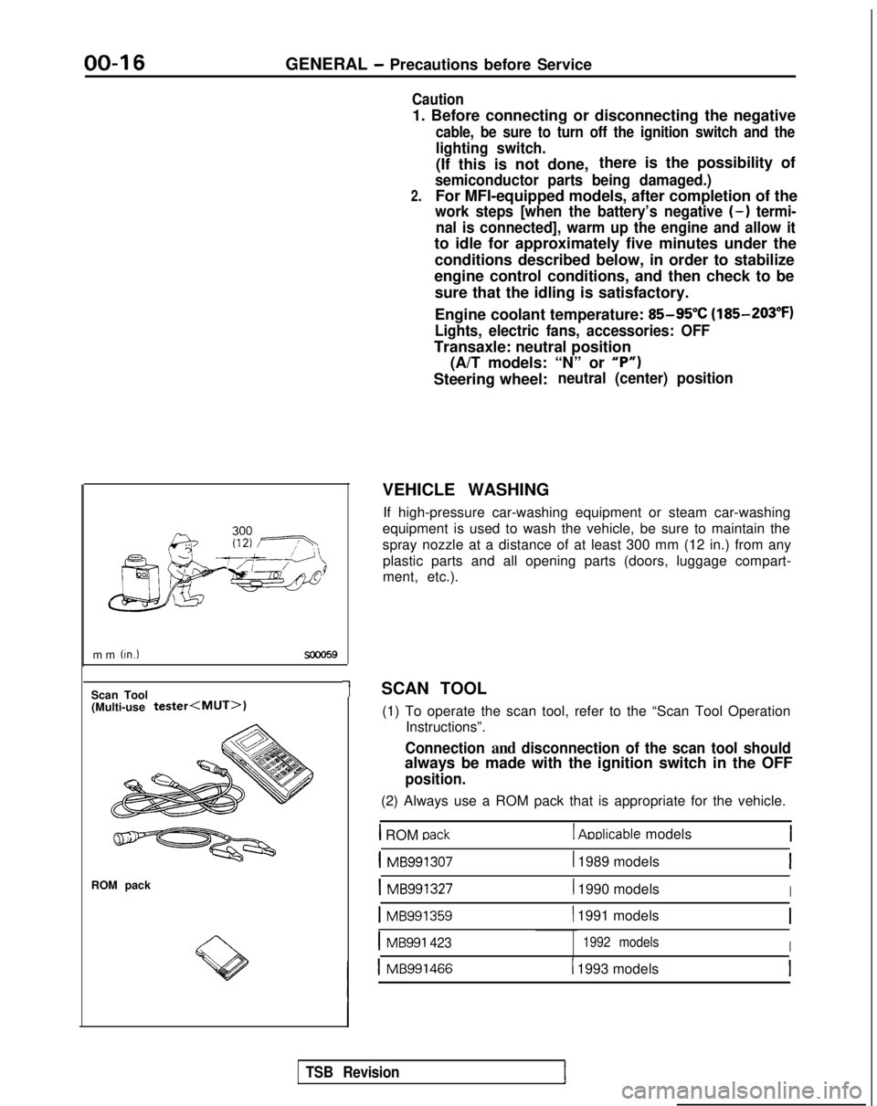
VEHICLE WASHING
If high-pressure car-washing equipment or steam car-washing
equipment is used to wash the vehicle, be sure to maintain the
spray nozzle at a distance of at least 300 mm (12 in.) from any plastic parts and all opening parts (doors, luggage compart-
ment, etc.).
SCAN TOOL (1) To operate the scan tool, refer to the “Scan Tool Operation Instructions”.
Connection and disconnection of the scan tool should
always be made with the ignition switch in the OFF
position.
(2) Always use a ROM pack that is appropriate for the vehicle.
1 ROM oack1 Aoblicable models
1 MB9913071 1989 modelsI
1 MB9913271 1990 modelsI
1 MB991359( 1991 models
IMB991 4231992 modelsI
1 MB9914661 1993 models
TSB Revision
Page 37 of 1273
GENERAL -Lubrication and Maintenance/Recommended Lubricants and Lubricant Capacities Table00-35
If premium unleaded gasoltne IS not available,
MATERIALS ADDED TO FUEL
unleaded gasoline having a octane rating of 87 or
91 RON (Research Octane Number) may be used. Indiscriminate use of fuel system cleaning agents
In this case, the performance and fuel consumption should be avoided. Many of these materials
in-
WIII suffer a little degradatron.tended for gum and varnish removal may contain
highly active
solvents or similar ingredients that can
be harmful to gasket and diaphragm materials used
in fuel system component parts.
Gasolines containing alcohol
Some gasolrnes sold at service stations contain
alcohol, although they may not be SC identified. Use
of fuels containing alcohol is not recommended
unless the nature of the blend can be
determrned
as being satisfactory.
Gasohol
- A mixture of 10% ethanol (grain alcohol)
and 90% unleaded gasoline may be used
In your
car. If
driveability problems are experienced as a
result of using gasohol, it IS recommended that the
car be operated on gasoline. Methanol
- Do not use gasolines containing
methanol (wood alcohol). Use of this type of
alcohol can result in vehicle performance deteriora-
tion and damage critical parts in the fuel system
components. Fuel system damage and performance
problems, resulting from the use of gasolines
containing methanol, may not be covered by the
new car warranty.
Gasolines containing MTBE (Methyl Tertiary Butyl
Ether)
Unleaded gasolrne containrng
15% or less MTBE
may be used in your car. (Fuel containing MTBE
over 15% vol. may cause reduced engine per-
formance and produce vapor lock or hard starting.) RECOMMENDED
LUBRICANTS AND
LUBRICANT CAPACITIES TAB,&-
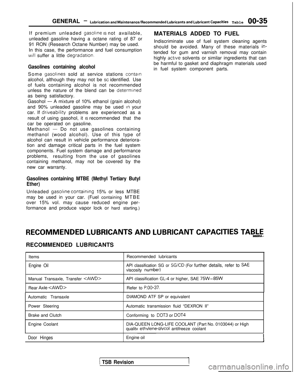
RECOMMENDED LUBRICANTS
Items
Engine Oil
Recommended lubricants
API classification SG or SGKD (For further details, refer to SAEviscosity number)
Manual Transaxle, Transfer
Rear Axle
API classification GL-4 or higher, SAE 75W-85W
Refer to P.OO-37.
Automatic Transaxle
Power Steering
Brake and Clutch
Engine Coolant DIAMOND ATF SP or equivalent
Automatic transmission fluid “DEXRON II” Conforming to
DOT3 or DOT4
DIA-QUEEN LONG-LIFE COOLANT (Part No. 0103044) or High
qualitv ethvlene-qlvcol
antifreeze coolant
Door HingesEngine oil
1 TSB Revision
Page 38 of 1273
00-36
GENERAL -Recommended Lubricants and Lubricant Capacities Table
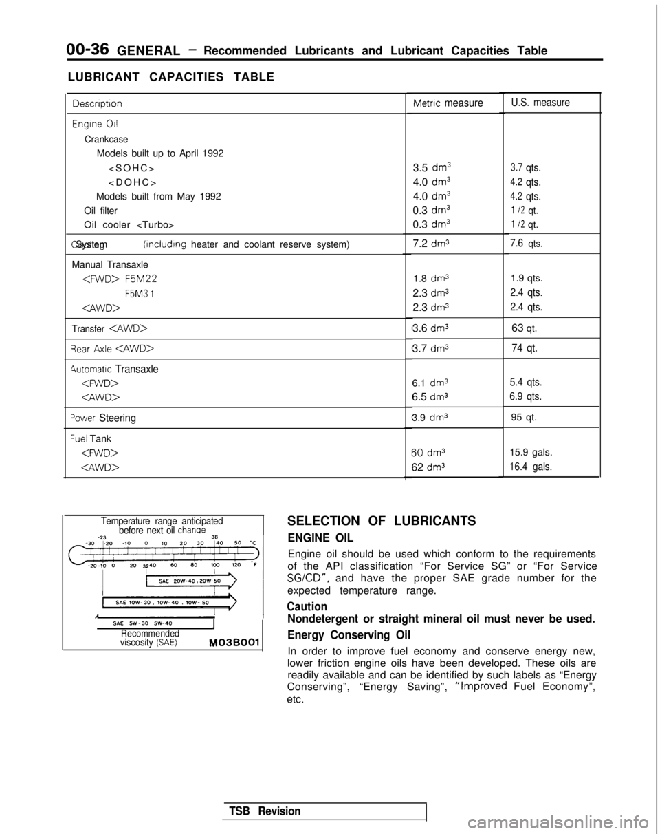
LUBRICANT CAPACITIES TABLE
Descrrptron
Engrne 011
Crankcase
Models built up to April 1992
Models built from May 1992
Oil filter
Oil cooler
(rncludrng heater and coolant reserve system)
Manual Transaxle
F5M3
1
Transfer
qear Axle
4utomatrc Transaxle
‘ower Steering %el
Tank
Metric measure
3.5 dm3
4.0 dm3
4.0 dm3
0.3 dm3
0.3 dm3
7.2 dm3
1.8 dm31.9 qts.
2.3
dm32.4 qts.
2.3 dm32.4 qts.
3.6 dm363 qt.
3.7
dm374 qt.
6.1 dm3
6.5 dms
3.9 dm3 60
dm3
62 dm3
U.S. measure
3.7qts.
4.2qts.
4.2qts.
1 I2qt.
1 I2qt.
7.6qts.
5.4 qts.
6.9 qts.
95 qt.
15.9 gals.
16.4 gals.
Temperature range anticipated before next oil chanae
SAE SW-30 SW-40IRecommendedviscosity (SAE) M03BOOl
SELECTION OF LUBRICANTS
ENGINE OIL
Engine oil should be used which conform to the requirements
of the API classification “For Service SG” or “For Service
SGKD”, and have the proper SAE grade number for the
expected temperature range.
Caution
Nondetergent or straight mineral oil must never be used.
Energy Conserving Oil
In order to improve fuel economy and conserve energy new,
lower friction engine oils have been developed. These oils are readily available and can be identified by such labels as “Energy
Conserving”, “Energy Saving”,
“Improved Fuel Economy”,
etc.
TSB Revision
Page 39 of 1273
GENERAL - Recommended LubricaMs and Lubricant Capacities Table 00-37
721004
4
Oil Identification Symbol
A standard
.symbol appears on the top of oil containers and has
three district areas for identifying various aspects of the oil.
The top
polqion will indicate the quality of the oil. The center
portion will show the SAE viscosity grade, such as SAE lOW-30.
“Energy Conserving” shown in the lower portion,
indicates that the oil has fuel-saving capabilities.
REAR AXLE
API classificationGL-5 or higher
Anticipated temperature range
Above -23°C
(- 10°F)
-23°C to --34°C (-10°F
to -30°F)
Viscosity range
SAE 90
SAE 85W-90SAE 8OW-90
SAE 8OW. SAE 8OW-90
Below
-34°C
(-30°F)SAE 75W
SELECTION OF COOLANT
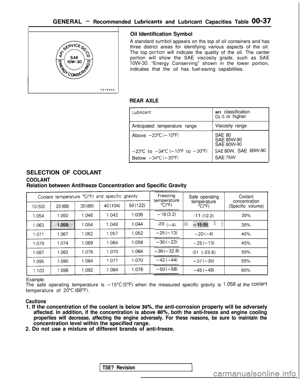
COOLANT
Relation between Antifreeze Concentration and Specific Gravity
Safe operatingCoolant
temperatureconcentration
“C(“F)(Specific volume)
-11 (12.2) 30%
-20
t-4)(,.‘_ -+j{@, ‘, :;35%
-2O(-4)40%
-25(-13)45%
-31 (-23.8) 50%
-37(-35)55%
-45(-49)60%
Example:
The safe operating temperature is - 15°C (5°F) when the measured specific gravity is 1.058 at the Coolant
temperature of 20°C (68°F).
Cautions
1. If the concentration of the coolant is below 30%, the anti-corrosion property will be adversely
affected. In addition, if the concentration is above 60%, both the anti-freeze and engine cooling
properties will decrease, affecting the engine adversely. For these reas\
ons, be sure to maintain the
concentration level within the specified range.
2. Do not use a mixture of different brands of anti-freeze.
TSE? Revision
Page 40 of 1273
00-38GENERAL- Scheduled Maintenance Table
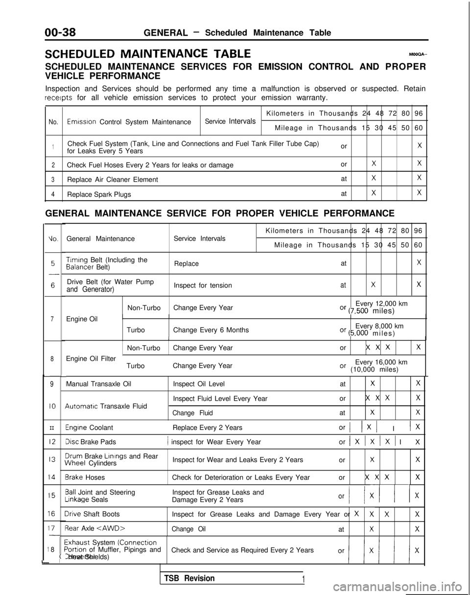
SCHEDULED MAINTENANCE
TABLEMOOOA-
SCHEDULED MAINTENANCE SERVICES FOR EMISSION CONTROL AND PROPER
VEHICLE PERFORMANCE
Inspection and Services should be performed any time a malfunction is ob\
served or suspected. Retain receipts
for all vehicle emission services to protect your emission warranty.
Kilometers in Thousands 24 48 72 80 96
No.Emwsron Control System MaintenanceService IntervalsMileage in Thousands 15 30 45 50 60
1Check Fuel System (Tank, Line and Connections and Fuel Tank Filler Tube\
Cap) orXfor Leaks Every 5 Years
2Check Fuel Hoses Every 2 Years for leaks or damage orXX
3Replace Air Cleaner ElementatXX
4Replace Spark PlugsatXX
GENERAL MAINTENANCE SERVICE FOR PROPER VEHICLE PERFORMANCE
L
1
1
1
1
1
i
IO.General Maintenance
Service Intervals
7Engine Oil
8
9
IO
III2
I3
14
15
I6
I71
8
L
I
I
I
I
I\
I
II
I
I
;(
Kilometers in Thousands 24 48 72 80 96
Mileage in Thousands 15 30 45 50 60 Timing
Belt (Including the Balancer
Belt)
ReplaceatX
Drive Belt (for Water Pump
Inspect for tensionatXXand Generator)
Non-TurboChange Every Year Every 12,000 kmOr (7,500 miles)
Turbo Change Every 6 Months Every 8,000 km
Or (5.000 miles
)
II
Non-Turbo
Change Every Year or X X XX
Every 16,000 kmOr (10,000 miles)
Engine Oil Filter
TurboChange Every Year
Manual Transaxle Oil 4utomatrc
Transaxle Fluid Inspect Oil Level
at
XX
Inspect Fluid Level Every Yearor X X XX
Change FluidatXX
Engine Coolant
Replace Every 2 YearsOrI 1x1 I IX
Disc Brake Pads1 inspect for Wear Every Yearor/XlXlXl I
X
3rum
Brake Linings
and Rear iNheel
Cylinders Inspect for Wear and Leaks Every 2 Years
or
XX
3rake HosesCheck for Deterioration or Leaks Every Year or X X XX
3all Joint and SteeringInspect for Grease Leaks and-inkage
Seals
Damage Every 2 Years
Or I/ XII x
Irive Shaft Boots Inspect for Grease Leaks and Damage Every Year or XXXX
3ear Axle
Exhaust System (Connectron>ortion of Muffler, Pipings and
Check and Service as Required Every 2 YearsConverter Heat Shields)
TSB Revision1
Page 46 of 1273
GENERAL -Maintenance Service
(1O)Star-t engine and allow to idle for at least two minutes.
Then, with parking brake on, move selector
fever
momentarily to each position, ending in “N” Neutral
position.
(11)Add sufficient ATF to bring fluid level to lower mark.
Recheck fluid level after transaxle is at normal Operating
temperature. Fluid level should be between upper and lower marks of
“HOT” range, Insert dipstick fully to prevent dirt from
entering transaxle.
OOA0051
11 .ENGINE
COOLANT (Change)MOOSEEAC
Check the cooling system parts, such as radiator, heater,
and oil cooler hoses, thermostat and connections for
leakage and damage.
CHANGE COOLANT
1. Remove the radiator cap.
2. Loosen the drain plug to drain the coolant.
3. Drain the coolant from the reserve tank.
4. After draining the coolant, tighten the drain plug securely.
5.Supply the coolant into the radiator until it is filled up to
its filler neck.
6. Supply the coolant into the reserve tank.
7. After warming the engine until the thermostat opens, remove the radiator cap and check the coolant level.
8.Supply the coolant into the radiator until it is filled up to
its filler neck, and install the radiator cap securely.
9.Fill the reserve tank with coolant up to the “FULL” line.
14K512
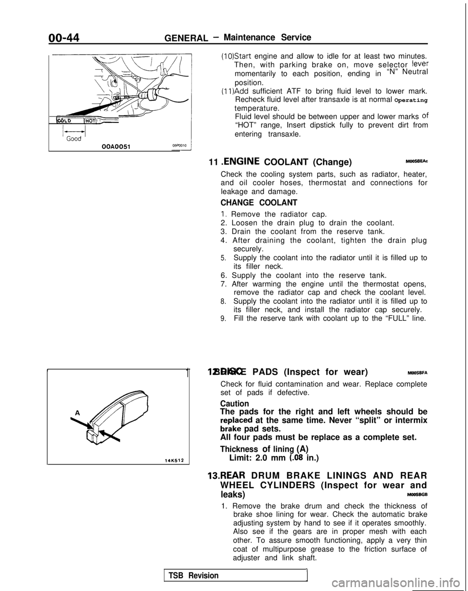
1 12.DISC BRAKE PADS (Inspect for wear) MWSBFA
Check for fluid contamination and wear. Replace complete
set of pads if defective.
Caution
The pads for the right and left wheels should be
reDlaced at the same time. Never “split” or intermix
brkke pad sets.
All four pads must be replace as a complete set.
Thickness of lining (A)
Limit: 2.0 mm (.08 in.)
13.REAR DRUM BRAKE LININGS AND REAR
WHEEL CYLINDERS (Inspect for wear and
leaks)MOOSBGB
1. Remove the brake drum and check the thickness of brake shoe lining for wear. Check the automatic brake
adjusting system by hand to see if it operates smoothly.
Also see if the gears are in proper mesh with each
other. To assure smooth functioning, apply a very thin
coat of multipurpose grease to the friction surface of
adjuster and link shaft.
TSB Revision1
Page 48 of 1273
00-46GENERAL - Table of Main Sealants and Adhesives
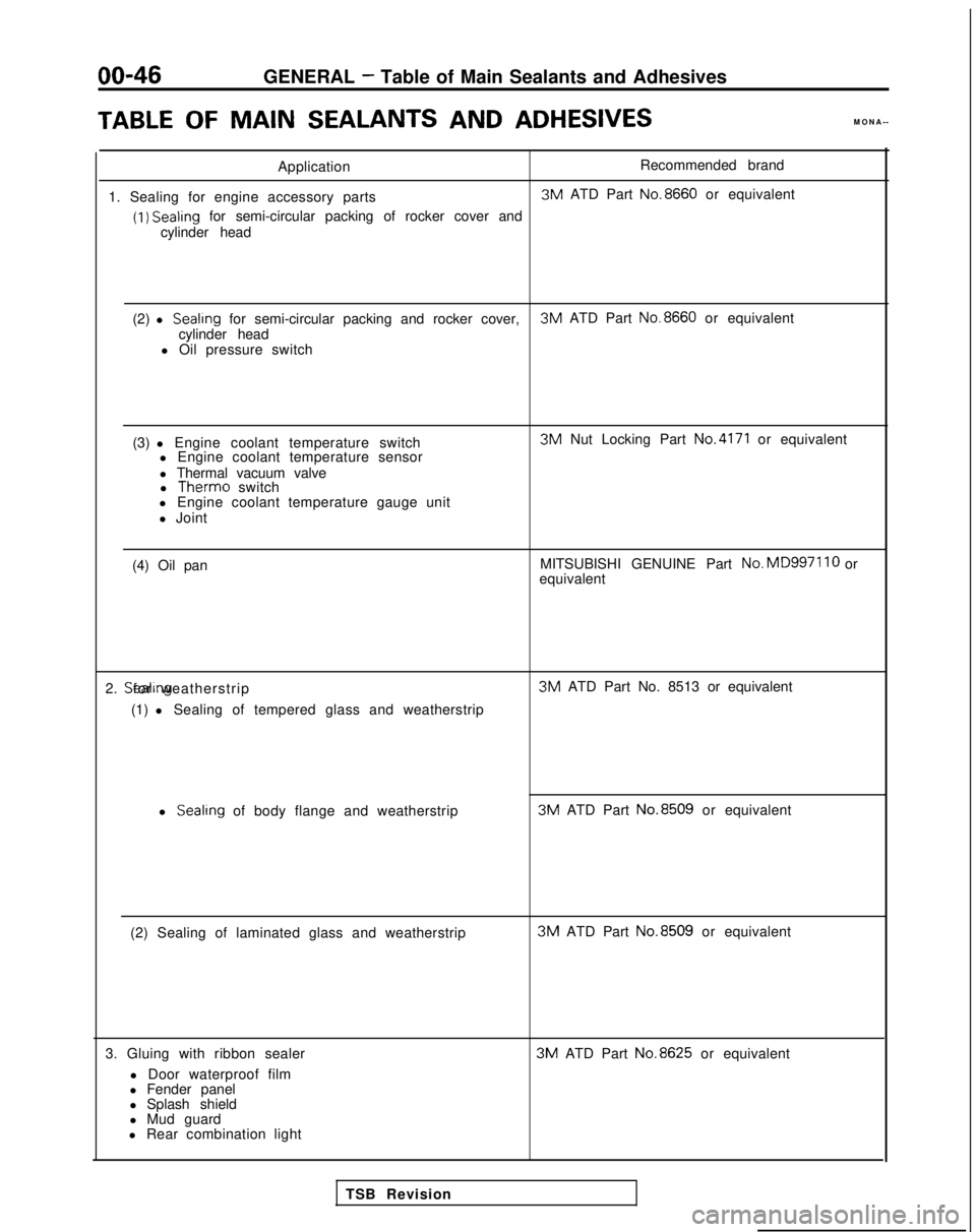
TABLEOF MAINSEALANTS
AND
ADHESIVES
MONA--
Application Recommended brand
1. Sealing for engine accessory parts 3M
ATD Part No.8660
or equivalent
(1) Sealing
for semi-circular packing of rocker cover and
cylinder head
(2) l
Sealrng for semi-circular packing and rocker cover, 3M
ATD Part No.8660
or equivalent
cylinder head
l Oil pressure switch
(3) l Engine coolant temperature switch l Engine coolant temperature sensor
l Thermal vacuum valvel Therm0
switch
l Engine coolant temperature gauge unit
l Joint 3M
Nut Locking Part
No.4171 or equivalent
(4) Oil pan MITSUBISHI GENUINE Part No.MD997110
or
equivalent
2. Sealing for weatherstrip
(1) l Sealing of tempered glass and weatherstrip 3M
ATD Part No. 8513 or equivalent
l Sealing
of body flange and weatherstrip 3M
ATD Part No.8509
or equivalent
(2) Sealing of laminated glass and weatherstrip 3M
ATD Part No.8509
or equivalent
3. Gluing with ribbon sealer l Door waterproof film
l Fender panel
l Splash shield
l Mud guard 3M
ATD Part No.8625
or equivalent
l Rear combination light TSB Revision
Page 57 of 1273
ENGINE
OlR0340
1
SERVICE ADJUSTMENT PROCEDU$$o
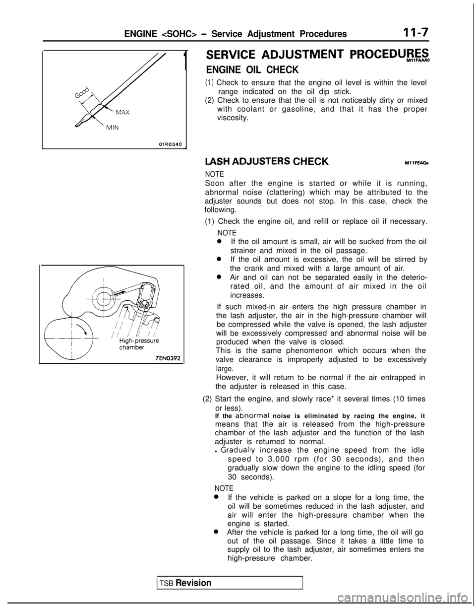
ENGINE OIL CHECK
(1) Check to ensure that the engine oil level is within the level
range indicated on the oil dip stick.
(2) Check to ensure that the oil is not noticeably dirty or mixed
with coolant or gasoline, and that it has the proper
viscosity. IASH
ACIJUSTERS CHECKMllFEAGa
NOTE
Soon after the engine is started or while it is running,
abnormal noise (clattering) which may be attributed to the
adjuster sounds but does not stop. In this case, check the
following.
(1) Check the engine oil, and refill or replace oil if necessary.
NOTE
0If the oil amount is small, air will be sucked from the oil
strainer and mixed in the oil passage.
0If the oil amount is excessive, the oil will be stirred by
the crank and mixed with a large amount of air.
0Air and oil can not be separated easily in the deterio- rated oil, and the amount of air mixed in the oil
increases.
If such mixed-in air enters the high pressure chamber in
the lash adjuster, the air in the high-pressure chamber will be compressed while the valve is opened, the lash adjuster
will be excessively compressed and abnormal noise will be produced when the valve is closed.
This is the same phenomenon which occurs when the
valve clearance is improperly adjusted to be excessively
large.
However, it will return to be normal if the air entrapped in
the adjuster is released in this case.
(2) Start the engine, and slowly race* it several times (10 times or less).
If the
ablnormal noise is eliminated by racing the engine, it
means that the air is released from the high-pressure
chamber of the lash adjuster and the function of the lash
adjuster is returned to normal.
l
Graclually increase the engine speed from the idle
speed to 3,000 rpm (for 30 seconds), and then
gradually slow down the engine to the idling speed (for
30 seconds).
NOTE 0
If the vehicle is parked on a slope for a long time, the
oil will be sometimes reduced in the lash adjuster, and
air will enter the high-pressure chamber when the
engine is started. 0
After the vehicle is parked for a long time, the oil will go
out of the oil passage. Since it takes a little time to
supply oil to the lash adjuster, air sometimes enters the
high-pressure chamber.
1 TSB Revision
Page 58 of 1273
II-8ENGINE
8 VALVE
W Tlmlng belt side
il6
16
727
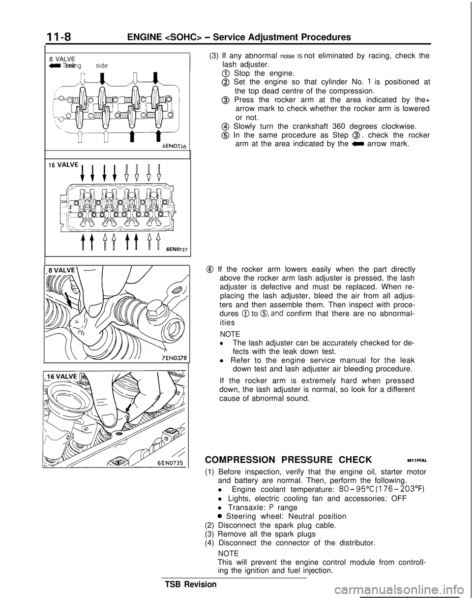
(3) If any abnormal noise IS not eliminated by racing, check the
lash adjuster.
@ Stop the engine.
@ Set the engine so that cylinder No. 1 is positioned at
the top dead centre of the compression.
@ Press the rocker arm at the area indicated by the+ arrow mark to check whether the rocker arm is lowered
or not.
@ Slowly turn the crankshaft 360 degrees clockwise.
@ In the same procedure as Step 0, check the rocker
arm at the area indicated by the
0 arrow mark.
@ If the rocker arm lowers easily when the part directly
above the rocker arm lash adjuster is pressed, the lash
adjuster is defective and must be replaced. When re-
placing the lash adjuster, bleed the air from all adjus-
ters and then assemble them. Then inspect with proce-
dures
@ to 0, and confirm that there are no abnormal-
ities
NOTE
lThe lash adjuster can be accurately checked for de-
fects with the leak down test.
l Refer to the engine service manual for the leak down test and lash adjuster air bleeding procedure.
If the rocker arm is extremely hard when pressed
down, the lash adjuster is normal, so look for a different
cause of abnormal sound.
COMPRESSION PRESSURE CHECK
MllFFAL
(1) Before inspection, verify that the engine oil, starter motor and battery are normal. Then, perform the following.
l Engine coolant temperature:
80- 95°C
(176- 203°F)
l Lights, electric cooling fan and accessories: OFF
l Transaxle:
P range
0 Steering wheel: Neutral position
(2) Disconnect the spark plug cable.
(3) Remove all the spark plugs
(4) Disconnect the connector of the distributor.
NOTE
This will prevent the engine control module from controll- ing the ignition and fuel injection.
TSB Revision