oil type MITSUBISHI GALANT 1989 Service Owner's Guide
[x] Cancel search | Manufacturer: MITSUBISHI, Model Year: 1989, Model line: GALANT, Model: MITSUBISHI GALANT 1989Pages: 1273, PDF Size: 37.62 MB
Page 816 of 1273

25-2PROPELLER SHAFT - Specifications
SPEClFlCATjONS
The AWD vehicles have been discontinued from 1993 models.
GENERAL SPECIFICATIONSM2scA-
Specifications
Items M/T
Arr
Propeller shaft
Type
4 joint propeller shaft
4 joint propeller shaft
Length x
O.D.mm (in.)
Front 707 x 50.8 (27.8
x 2.00)707 x 50.8 (27.8 x
2.00)
Center 777.5 x 65 (30.8 x 2.56)
764.4 x
65 (30.1 x
2.56)
Rear530.5 x 50.8 (20.9 x
2.00)543.3 x 50.8 (21.4 x
2.00)
Universal joint Type
No. 1 (front) Cross typeCross typeNo.2
(center front)
Cross type Cross typeNo.3
(center rear) [Lobro joint
Equal velocity type Equal velocity type
No. 4 (rear) or
D.O.J.1Cross type
Cross type
Cross type universal joint bearing Needle roller bearing (oilless
type) Needle roller bearing (oilless
type)
Cross type universal joint
Journal O.D. mm (in.) 14.689 l.5783)
14.689 i.5783)
Equal velocity joint type Lobro joint
(oilless type)D.O.J. (oilless
type)
Equal velocity joint size O.D.mm
(in.) 94
(3.7)94 (3.7)
NOTEPropeller shaft length indicates the length between the center points of\
each joint.
SERVICE SPECIFICATIONSMz5c&-
Items Specifications
Standard value Journal axial play mm (in.)
0.02-0.06 (.0008-.0024)
Limit
Propeller shaft runout(Dial
indicator reading)
Frontmm (in.) 0.6 t.024) or less
Center mm (in.)
0.6
t.024) or less
Rearmm (in.)
0.6 (.024) or less
TORQUE SPECIFICATIONSMzxc-
Items1 Nm
Center bearing self locking nut
30-4022-29
Flange yoke to differential companion flange
30-3522-25
Center propeller shaft to center yoke
160-220116-159
Rear propeller shaft to companion flange
160-220116-159
Companion flange to Lobro joint assembly
30-4022-29
Companion flange to D.O.J. assembly
30-4022-2
9
ft.lbs.
TSB Revision
Page 842 of 1273
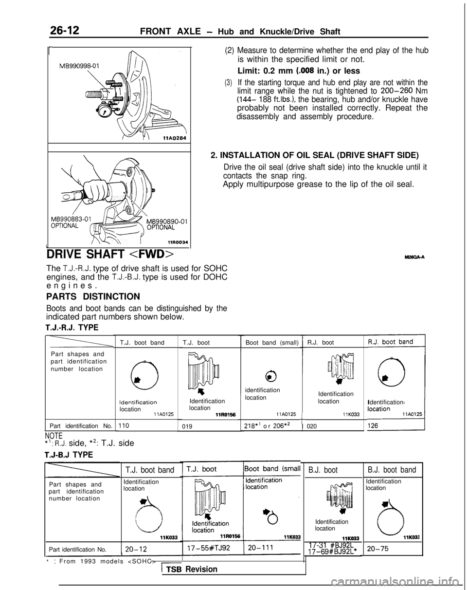
26-12FRONT AXLE - Hub and Knuckle/Drive Shaft
(2) Measure to determine whether the end play of the hub
is within the specified limit or not.
Limit: 0.2 mm
(.008 in.) or less
(3)If the starting torque and hub end play are not within the
limit range while the nut is tightened to 200-260 Nm
(144-
188 ft.lbs.), the bearing, hub and/or knuckle have
probably not been installed correctly. Repeat the
disassembly and assembly procedure.
r MB990998-01
2. INSTALLATION OF OIL SEAL (DRIVE SHAFT SIDE)
Drive the oil seal (drive shaft side) into the knuckle until it
contacts the snap ring.
Apply multipurpose grease to the lip of the oil seal.
MB990890-01
L
DRIVE SHAFT
The T.J.-R.J. type of drive shaft is used for SOHC
engines, and the
T.J.-B.J. type is used for DOHC
engines
.
PARTS DISTINCTION
Boots and boot bands can be distinguished by the
indicated part numbers shown below.
T.J.-R.J. TYPE
R.J. boot
T.J. boot band Boot band (small)
T.J. boot
a
,;: I
III 1it jii’
w
Part shapes and
part identification
number location
0
identification
location Identification
location Identification Identification
Identification
location location llA0125
llRO1!56
110019
llK033218” or
206*2 llA0125tI 020
Part identification No.
NOTE *‘:
R.J. side, *2: T.J. side
T.J-B.J TYPE
B.J. boot band
Identification
location
B.J. boot
Part shapes and
part identification number location
T.J. boot band
Identification
location
llK033
Part identification No. 20-12
Identification
location
llKO3317-31 #BJ92L17-69#BJ92L*20-75
i:: From 1993 models
Revision
Page 862 of 1273
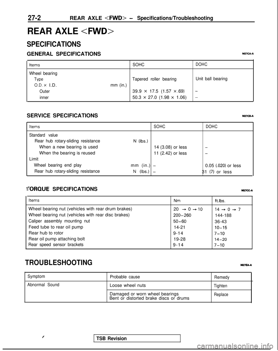
27-2REAR AXLE
REAR AXLE
SPECIFICATIONS
GENERAL SPECIFICATIONSM2?CA-A
Items
Wheel bearing
Type
O.D. x I.D.
Outer
inner SOHC
DOHC
Tapered roller bearing
Unit ball bearing
mm (in.)
39.9 x 17.5 (1.57 x ,691-
50.3 x 27.0 (1.98 x 1.06)-
SERVICE SPECIFICATIONShl27CEA
Items
Standard value
Rear hub rotary-sliding resistance
When a new bearing is used
When the bearing is reused
Limit Wheel bearing end playRear hub rotary-sliding resistance
SOHC
N (Ibs.)
14 (3.08) or less
11 (2.42) or less
mm (in.)
-
N (Ibs.) -
DOHC
-
-
0.05 i.020) or less
31
(7) or less
1i-ORQUE SPECIFICATIONS MnCGA
Items
Wheel bearing nut (vehicles with rear drum brakes)
Wheel bearing nut (vehicles with rear disc brakes)
Caliper assembly mounting nut
Feed tube to rear oil pump
Rear hub to rotor
Rear oil pump attaching bolt
Rear speed sensor brackets
Nmft.lbs.
20 + 0 + IO14+0+7 200-260
144-188
50-6036-43
14-21
IO-15
9-147-10
19-2814-20
9-1
4
7-10
TROUBLESHOOTINGM27EA-A
Symptom
Abnormal SoundProbable cause
Loose wheel nuts
Damaged or worn wheel bearings
Bent or distorted brake discs or drums
Remedy
Tighten
Replace
TSB Revision
Page 890 of 1273
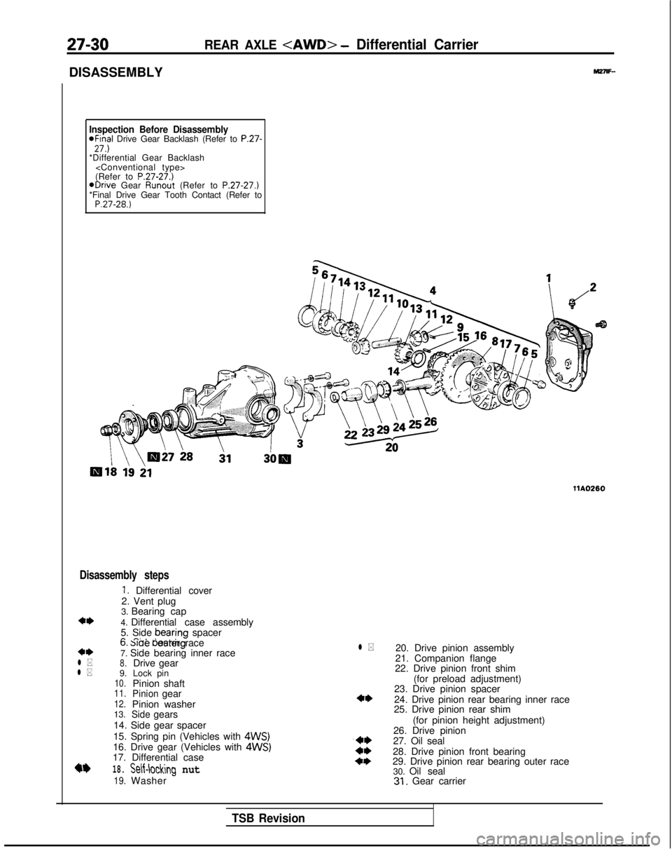
27-30
DISASSEMBLY
REAR AXLE
Inspection Before Disassembly*Final Drive Gear Backlash (Refer to P.27-27.)*Differential Gear Backlash
(Refer to
P.27-27.)@Drive Gear Runout
(Refer to P.27-27.)
*Final Drive Gear Tooth Contact (Refer to
P.27-28.)
llA0260
Disassembly steps
1. Differential cover
2. Vent plug
**l *
l *
3. Bearing cap
4. Differential case assembly
5. Side bearing
spacer
n n.* I0. slae oeanng outer race
7. Side bearing inner race
8.Drive
9. gear
10.Lock pin
Pinion shaft
11.Pinion12.gear
Pinion washer
13.
Sidegears
14. Side gear spacer
15. Spring pin (Vehicles with
4WS)16. Drive gear (Vehicles with 4WS)17. Differential case
18.
19.
Self-loclhg nut
Washer
l *20. Drive pinion assembly
21. Companion flange
22. Drive pinion front shim
(for preload adjustment)
23. Drive pinion spacer
24. Drive pinion rear bearing inner race
25. Drive pinion rear shim
(for pinion height adjustment)
26. Drive pinion
27. Oil seal
28. Drive pinion front bearing
29. Drive pinion rear bearing outer race 30. Oil seal
31. Gear carrier
TSB Revision
Page 905 of 1273
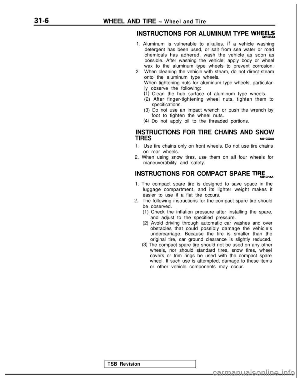
31-6WHEEL AND TIRE - Wheel and Tire
INSTRUCTIONS FOR ALUMINUM TYPE WHk&g
1. Aluminum is vulnerable to alkalies. If
a vehicle washing
detergent has been used, or salt from sea water or road
chemicals has adhered, wash the vehicle as soon as
possible. After washing the vehicle, apply body or wheel
wax to the aluminum type wheels to prevent corrosion.
2.When cleaning the vehicle with steam, do not direct steam
onto the aluminum type wheels.
When tightening nuts for aluminum type wheels, particular- ly observe the following:
(I) Clean the hub surface of aluminum type wheels.
(2) After finger-tightening wheel nuts, tighten them to specifications.
(3) Do not use an impact wrench or push the wrench by foot to tighten the wheel nuts.
(4) Do not apply oil to the threaded portions.
INSTRUCTIONS FOR TIRE CHAINS AND SNOW
TIRES M31GGbl
1.Use tire chains only on front wheels. Do not use tire chains
on rear wheels.
2. When using snow tires, use them on all four wheels for maneuverability and safety.
INSTRUCTIONS FOR COMPACT SPARE TlR,E,,,,
1. The compact spare tire is designed to save space in theluggage compartment, and its lighter weight makes it
easier to use if a flat tire occurs.
2.The following instructions for the compact spare tire should be observed.
(1) Check the inflation pressure after installing the spare, and adjust to the specified pressure.
(2) Avoid driving through automatic car washes and over obstacles that could possibly damage the vehicle’s
undercarriage. Because the tire is smaller than the
original tire, car ground clearance is slightly reduced.
(3) The compact spare tire should not be used on any other wheels, nor should standard tires, snow tires, wheel
covers or trim rings be used with the compact spare
wheel. If such use is attempted, damage to these items
or other vehicle components may occur.
TSB Revision
Page 923 of 1273
33A-2FRONT SUSPENSION - Specifications
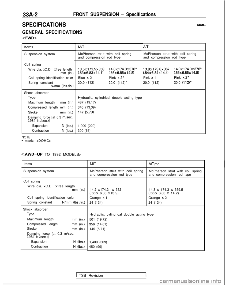
SPECIFICATIONS
GENERAL SPECIFICATIONS
Items
Suspension system
Coil springW
ire dia. x O.D. x free length
mm (in.)
Coil spring identification color
Spring constant N/mm (IbsAn.)
Shock absorber Type
Maximum length mm (in.)
Compressed length mm (in.)
Stroke mm (in.)
Damping force [at 0.3 misec.
t.984 ft./sec.)l
ExpansionN (Ibs.)
Contraction
N (Ibs.) MIT Al-r
McPherson strut with coil spring McPherson strut with coil spring
and compression rod type and compression rod type
13.5x173.5x358 14.0x174.0x376*(.53x6.83x14.1) (55x6.85x14.8)
Blue x 2
Pink x
2”
20.0 (112)20.0 (112)”
13.8x173.8x367 14.0x174.0x376*(54x6.84x14.4) (.55x6.85x14.8)
Pink x 1 Pink x
2”
20.0 (112) 20.0 (112)*
Hydraulic, cylindrical double acting type
487 (19.17)
340 (13.39) 147
(5.j9)
1,000 (220)
300 (66)
NOTE* mark:
Items
Suspension system
Coil spring W
ire dia. x O.D. x free length
mm (in.)
Coil spring identification color
Spring constant N/mm
(Ibs./in.)
Shock absorberType
Maximum length mm (in.)
Compressed length mm (in.)
Stroke mm (in.)
Damping force [at 0.3
m/set.t.984 ft./set.)]
ExpansionN (Ibs.)
ContractionN (Ibs.)
MIT A/T, Turbo
McPherson strut with coil spring McPherson strut with coil spring
and compression rod type and compression rod type
14.2 x 174.2 x
352(56
x
6.86 x 13.9)
Orange x
1
24 (134) 14.3 x
174.3 x
359.5(56 x
6.86 x
14.2)
Orange x
2
24 (134)
Hydraulic, cylindrical double acting type
501 (19.72)
356 (14.01) 145 (5.71)
1,400 (309)
450 (99)
1 TSB Revision
Page 941 of 1273
33B-2ACTIVE-ELECTRONIC CONTROL SUSPENSION - Specifications
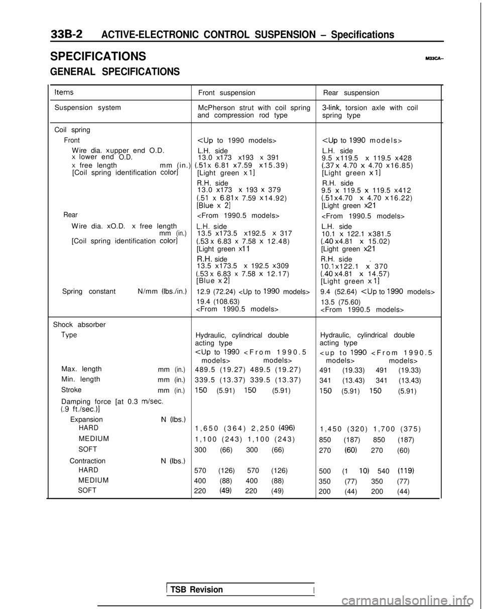
SPECIFICATIONSM33CA-
GENERAL SPECIFICATIONS
ItemsFront suspensionRear suspension
Suspension system McPherson strut with coil spring 3-link,
torsion axle with coil
and compression rod type spring type
Coil spring
Front
Wire dia. x upper end O.D.
L.H. side L.H. side
x lower endO.D.13.0 x 173 x 193 x 391
9.5 x 119.5 x
119.5 x 428x free length
mm (in.) (51
x 6.81 x 7.59 x 15.39)(.37
x
4.70 x 4.70 x 16.85)
[Coil spring identification color1[Light green x II[Light green x
11
R.H. side R.H. side
13.0 x 173 x 193 x 379
9.5 x
119.5 x
119.5 x 412
;;lexx6$1 x 7.59
x 14.92) (51
x 4.70 x
4.70 x 16.22)U[Light green
x 21
Rear
W
ire dia. x O.D.
x free lengthL.H. side
L.H. side
mm(in.)13.5 x 173.5 x 192.5 X 317
10.1 x
122.1 x 381.5
[Coil spring identification color]
(.53 x 6.83 x 7.58
x
12.48)(.40 x 4.81 x
15.02)
[Light green x 11
[Light green x 21
R.H. side
R.H. side
13.5 x 173.5 x 192.5 x 30910.1
x 122.1 x. 370(53 x 6.83 x 7.58
x
12.17)(.40 x 4.81 x
14.57)
[Blue x 21[Light green
x
11
Spring constant N/mm (Ibs./in.)12.9 (72.24)
19.4 (108.63) 13.5 (75.60)
Shock absorber Type
Hydraulic, cylindrical double
Hydraulic, cylindrical double
acting type acting type
models> models>
models> models>
Max. length mm
(in.)489.5 (19.27) 489.5 (19.27) 491 (19.33) 491 (19.33)
Min. length mm
(in.)339.5 (13.37) 339.5 (13.37) 341 (13.43) 341 (13.43)
Stroke mm
(in.)150 (5.91) 150 (5.91)150 (5.91) 150 (5.91)
Damping force [at 0.3
m/set.(.9 ft./sec.)l
ExpansionN (Ibs.)
HARD
1,650 (364) 2,250 (496)1,450 (320) 1,700 (375
)
MEDIUM 1,100 (243) 1,100 (243) 850 (187) 850 (187)
SOFT300 (66) 300 (66) 270 (60) 270 (60)
Contraction
N (Ibs.)
HARD
570 (126) 570 (126) 500 (1 IO) 540 (119)
MEDIUM400 (88) 400 (88) 350 (77) 350 (77)
SOFT220 (49) 220 (49)200 (44) 200 (44)
1 TSB RevisionI
Page 952 of 1273
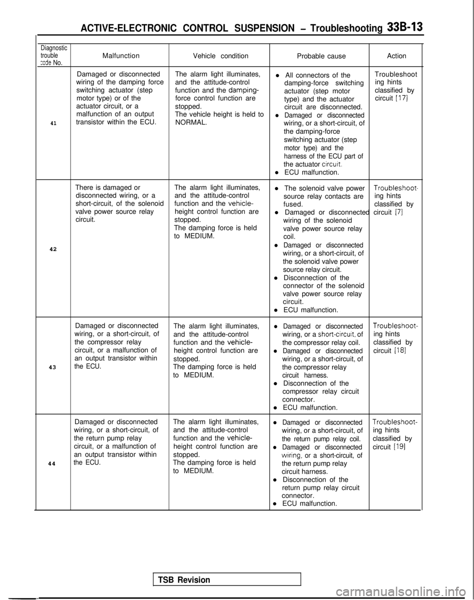
ACTIVE-ELECTRONIC CONTROL SUSPENSION - Troubleshooting 33B-13
Diagnostic
trouble
zode No.MalfunctionVehicle condition Probable causeAction
Damaged or disconnected The alarm light illuminates,
l All connectors of theTroubleshoot
wiring of the damping force and the attitude-control
damping-force switchinging hints
switching actuator (step function and the damping-
actuator (step motor classified by
motor type) or of the force control function are
type) and the actuatorcircuit
[ 171
actuator circuit, or a
stopped.
circuit are disconnected.
malfunction of an output The vehicle height is held to
l Damaged or disconnected41transistor within the ECU. NORMAL.
wiring, or a short-circuit, of
the damping-force
switching actuator (step
motor type) and the
harness of the ECU part of
the actuator circutt.
l ECU malfunction.
There is damaged or The alarm light illuminates,
l The solenoid valve power Troubleshoot-
disconnected wiring, or a and the attitude-control
short-circuit, of the solenoid source relay contacts are
ing hints
function and the
vehicle-fused. classified by
valve power source relay height control function are
circuit. l Damaged or disconnected circuit
(71stopped.
wiring of the solenoid
The damping force is held valve power source relay
to MEDIUM. coil.
42
l Damaged or disconnected
wiring, or a short-circuit, of
the solenoid valve power source relay circuit.
l Disconnection of the connector of the solenoid
valve power source relay
circuit.
l ECU malfunction.
Damaged or disconnected The alarm light illuminates,
l Damaged or disconnected Troubleshoot-
wiring, or a short-circuit, of and the attitude-control wiring, or a
short-circuit, ofing hints
the compressor relay function and the
vehicle-the compressor relay coil.classified by
circuit, or a malfunction of height control function are
l Damaged or disconnectedcircuit [I81an output transistor within
stopped.
43
the ECU.wiring, or a short-circuit, of
The damping force is held the compressor relay
to MEDIUM.
circuit harness.
l Disconnection of the
compressor relay circuit
connector.
l ECU malfunction.
Damaged or disconnected The alarm light illuminates,
l Damaged or disconnected Troubleshoot-
wiring, or a short-circuit, of and the attitude-control
wiring, or a short-circuit, ofing hints
the return pump relay function and the
vehicle-the return pump relay coil.classified by
circuit, or a malfunction of height control function are
l Damaged or disconnectedcircuit [I91an output transistor withinstopped.
the ECU.The damping force is heldwrring, or a short-circuit, of44
the return pump relay
to MEDIUM. circuit harness.
l Disconnection of the return pump relay circuit
connector.
l ECU malfunction.
TSB Revision
Page 1083 of 1273
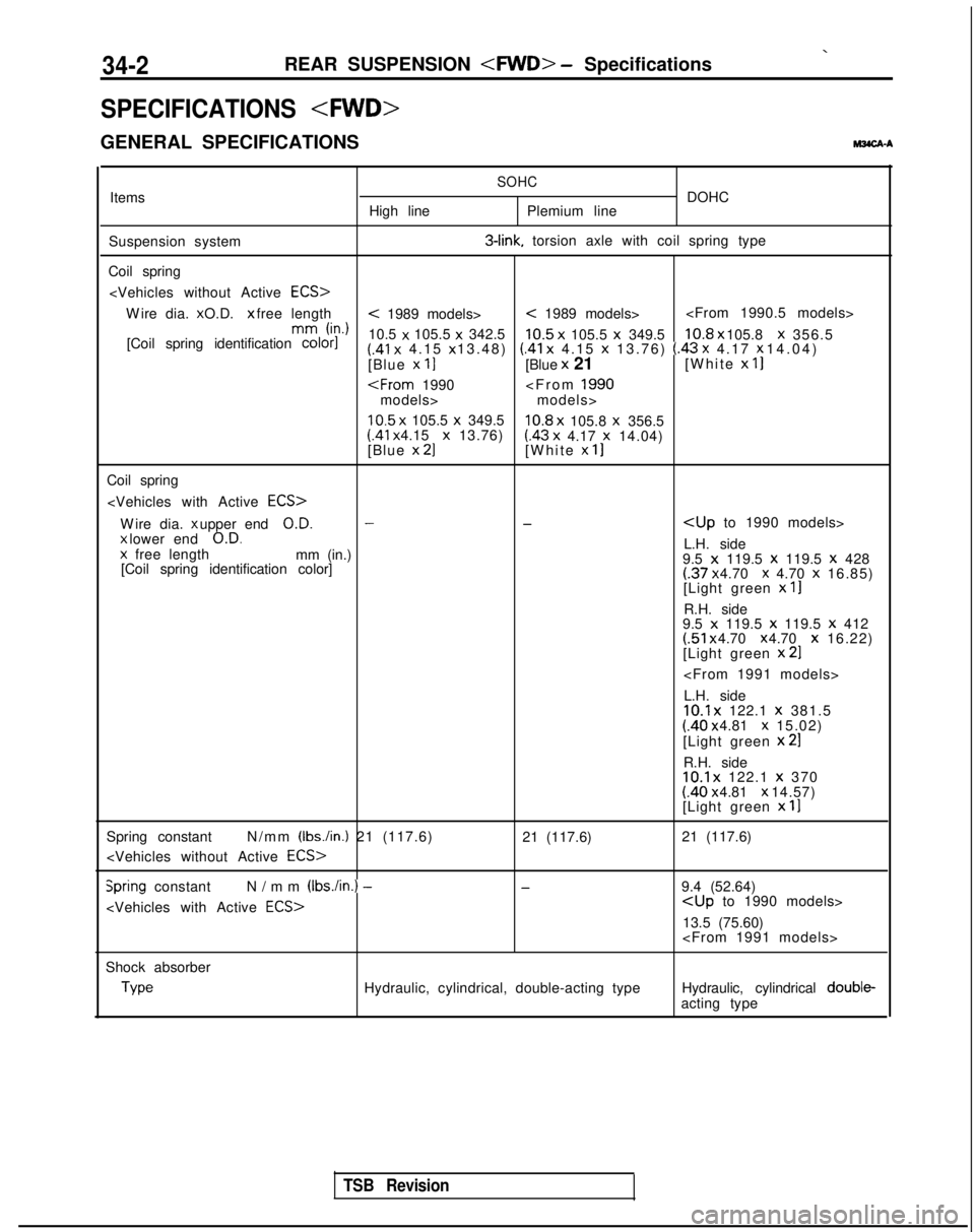
34-2REAR SUSPENSION
SPECIFICATIONS
GENERAL SPECIFICATIONS
M3CA-A
Items
Suspension system
Coil spring High lineSOHCDOHC
Plemium line 3-link.
torsion axle with coil spring type
Wire dia. x O.D. x free length
< 1989 models>< 1989 models>
h-d
[Coil spring identification color]
10.5 x
105.5 x
342.5
10.5 x
105.5 x
349.510.8 x 105.8 x
356.5(.41 x
4.15 x 13.48) (.41 x
4.15 x
13.76) (.43 x 4.17 x 14.04)
[Blue x 11[Blue x
21 [White x
II
models>
10.5 x
105.5 x
349.510.8 x
105.8 x
356.5 (41
x 4.15 x
13.76)(.43 x
4.17 x
14.04)
[Blue x 21[White x 11
Coil spring
Wire dia. x upper end
O.D.--
x lower end
O.D.L.H. side
x
free length
mm (in.)
9.5 x 119.5 x
119.5 x
428
[Coil spring identification color](.37 x 4.70 x 4.70 x
16.85)
[Light green x
II
R.H. side
9.5 x 119.5 x
119.5 x 412(.51 x 4.70 x 4.70 x
16.22)
[Light green x
21
L.H. side
10.1 x
122.1 x
381.5(.40 x 4.81 x 15.02)
[Light green x
21
R.H. side10.1 x
122.1 x
370 (.40 x 4.81 x 14.57)
[Light green x
11
Spring constant N/mm (Ibs./in.) 21 (117.6)
21 (117.6)
21 (117.6)
Spring constant
N/mm (Ibs./in.) -
-9.4 (52.64)
13.5 (75.60)
Shock absorber Type
Hydraulic, cylindrical, double-acting type
Hydraulic, cylindrical double-
acting type
TSB Revision
Page 1100 of 1273
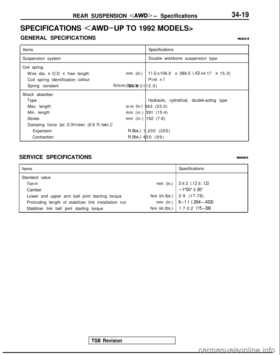
REAR SUSPENSION
SPECIFICATIONS
GENERAL SPECIFICATIONS M34cA-0
Items Specifications
Suspension system Double wishbone suspension type
Coil spring Wire dia. x
O.D. x
free length mm (in.)
11.0 x 106.0 x
389.5 (.43 x 4.17 x
15.3)
Coil spring identification colour
Pink x
1
Spring constant N/mm
(Ibs./in.) 20.0 (112.0)
Shock absorber Type
Hydraulic, cylindrical, double-acting type
Max. length mm
(in.) 583 (23.0)
Min. length mm (in.) 391 (15.4)
Stroke mm (in.) 192 (7.6)
Damping force [at 0.3m/sec.
(0.9
ft./sec.)l
ExpansionN (Ibs.) 1,200 (265
)
Contraction
N (Ibs.) 450 (99
)
SERVICE SPECIFICATIONS Items
Standard value
Toe-in
Camber mm (in.)
Lower and upper arm ball joint starting torque
Protruding length of stabilizer link installation nut
Stabilizer link ball joint starting torque Nm
(inlbs.)
mm (in.)
Nm
(inlbs.)
Specifications
TSB Revision
. .
3+3 (.12+.12)
-1”00’+30’
2-9 (17-78)
9-l 1 (.354-.433)
1.7-3.2 (15-28)