relay MITSUBISHI GALANT 1989 Service Manual Online
[x] Cancel search | Manufacturer: MITSUBISHI, Model Year: 1989, Model line: GALANT, Model: MITSUBISHI GALANT 1989Pages: 1273, PDF Size: 37.62 MB
Page 427 of 1273
FUEL SYSTEM
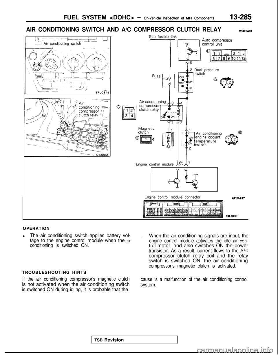
AIR CONDITIONING SWITCH AND A/C COMPRESSOR CLUTCH RELAYmt3n7.4al
Jk: L 1 /J l-k~-~+ L!- Air conditioning switch
0
/’
’ ’ -~.i>
‘\ /,
(\ QeF --:
’ -q,,T
(‘a/ A-.,>*/ \
) !I/ ,+f---J;I’,,p
s- / :\,$jy W/’
\mc-- -; --
\\ \\$ &
IF -~1. bI /~-~ i E--z
\ \I i
!
L-,-1&L.- ~~~~.
6FUO845 I
Sub fusible link
‘7 IpI Z%37°GZressor
2 Dual pressure
switch
1
t
Air conditioning OFF
engif’Ie codant* temperatureON switc
h
T
2
TSB Revision
Engine control module
,(65 1\7
v v
Engine control module connector6FU1457
OlLo838
OPERATION
l
The air conditioning switch applies battery vol-
tage to the engine control module when the
air
conditioning is switched ON.
TROUBLESHOOTING HINTS
If the air conditioning compressor’s magnetic clutch
is not activated when the air conditioning switch
is switched ON during idling, it is probable that the
.When the air conditioning signals are input, the
engine control module activates the idle air con-
trol motor, and also switches ON the power
transistor. As a result, current flows to the A/C
compressor clutch relay coil and the relay
switch is switched ON, the air conditioning
compressor’s magnetic clutch is activated.
cause is a malfunction of the air conditioning control
system.
Page 428 of 1273
13-286FUEL SYSTEM
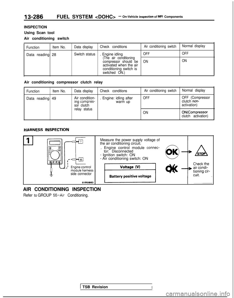
INSPECTION Using Scan tool
Air conditioning switch
Function Item No.
Data reading 28
Data displayCheck conditionsAir conditioning switchNormal
display
Switch status
. Engine idlingOFF OFF
(The air conditioning
compressor should beONONactivated when the air
conditioning switch is
switched ON.)
Air conditioning compressor clutch relay
Function
Item No.
Data reading 49
Data display
Check conditionsAir conditioning switchNormal display
Air condition-
. Engine: idling afterOFFOFF (Compressor
ing compres-warm up clutch non-
sor clutch
activation)
relay status ON
ONKompressorclutch activation)
HARNESS INSPECTION________ --- -__-. -- ~~-
Measure the power supply voltage of
the air conditioning circuit.
. Engine control module connec-tor: Disconnected- Ignition switch: ON+ Air conditioning switch: ON
side connector
AIR CONDITIONING INSPECTION
Refer to GROUP 55-Air Conditioning.
1 TSB RevisionI
Page 432 of 1273
13-290FUEL SYSTEM
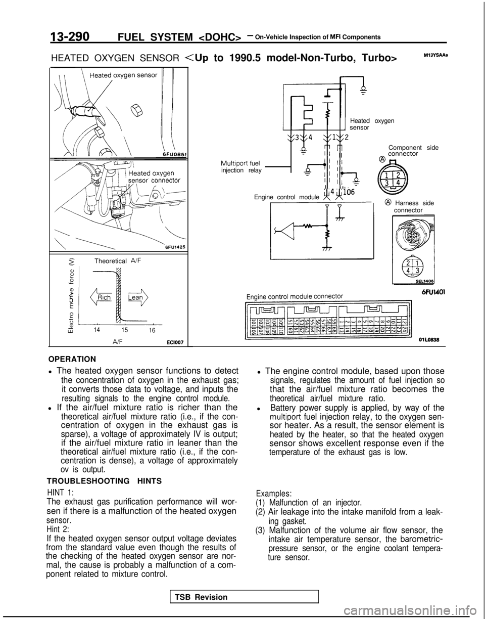
HEATED OXYGEN SENSOR
sensor connector
2Theoretical A/F
8.5
P.-
5
E
Pt;2Lw1415 16
AJFEC1007
Component side
Heated oxygen
. sensor
y3y4 $1y2
nri rlT” IIMultiport fuel
injection relayd; II
TII :‘aII Il. 7
Engine control module x4H106@ Harness side
connector
OlLoB38
OPERATION
l The heated oxygen sensor functions to detect
the concentration of oxygen in the exhaust gas;
it converts those data to voltage, and inputs the
resulting signals to the engine control module.
l If the air/fuel mixture ratio is richer than the
theoretical air/fuel mixture ratio (i.e., if the con-
centration of oxygen in the exhaust gas is
sparse), a voltage of approximately IV is output;
if the air/fuel mixture ratio in leaner than the
theoretical air/fuel mixture ratio (i.e., if the con-centration is dense), a voltage of approximately
ov is output.
TROUBLESHOOTING HINTS
HINT 1:
The exhaust gas purification performance will wor-
sen if there is a malfunction of the heated oxygen
sensor.
Hint 2:
If the heated oxygen sensor output voltage deviates
from the standard value even though the results of
the checking of the heated oxygen sensor are nor-
mal, the cause is probably a malfunction of a com-
ponent related to mixture control.
l The engine control module, based upon those
signals, regulates the amount of fuel injection so
that the air/fuel mixture ratio becomes the
theoretical air/fuel mixture ratio.
lBattery power supply is applied, by way of the
multiport fuel injection relay, to the oxygen sen-
sor heater. As a result, the sensor element is
heated by the heater, so that the heated oxygen
sensor shows excellent response even if the
temperature of the exhaust gas is low.
Examples:
(1) Malfunction of an injector.
(2) Air leakage into the intake manifold from a leak-
ing gasket.
(3) Malfunction of the volume air flow sensor, the intake air temperature sensor, the
barometric-
pressure sensor, or the engine coolant tempera-
ture sensor.
TSB Revision
Page 435 of 1273

FUEL SYSTEM
HEATED OXYGEN SENSOR
sensor connector
\ \
6FU1425
2
d6
25E
gt;a,W
TheoreWal A/F
14
15
16 A/F
EC1007
OPERATION
TROUBLESHOOTING HINTS INSPECTION-Using Scan tool
Refer to P.1.3-290.
HARNESS INSPECTION
connector Heated oxygen
sensor ComDonent
side
Multiport fuel
injection relay
Engine control module
Engine control module connector @
Harness side
connector
6FU1628
OlLO838
Measure the power supply voltage of
the heated oxygen sensor.
Connector: DisconnectedIgnition switch: O
N
,
TSB Revision
Page 437 of 1273
FUEL SYSTEM
of
MFI
Components13-295
Filter
Connector
Solenoid coil
Plunger
Needle valve -&$
lnjedtion6FUO51
Multiport
fuel injection relayMIBvrbA1
I
The area enclosed with ~~~~ is@I Harness side
applicable onlv for Turbo.
connector
Enginecofitrolmodule
Engine control module connectorI6FU1547
OlLo63
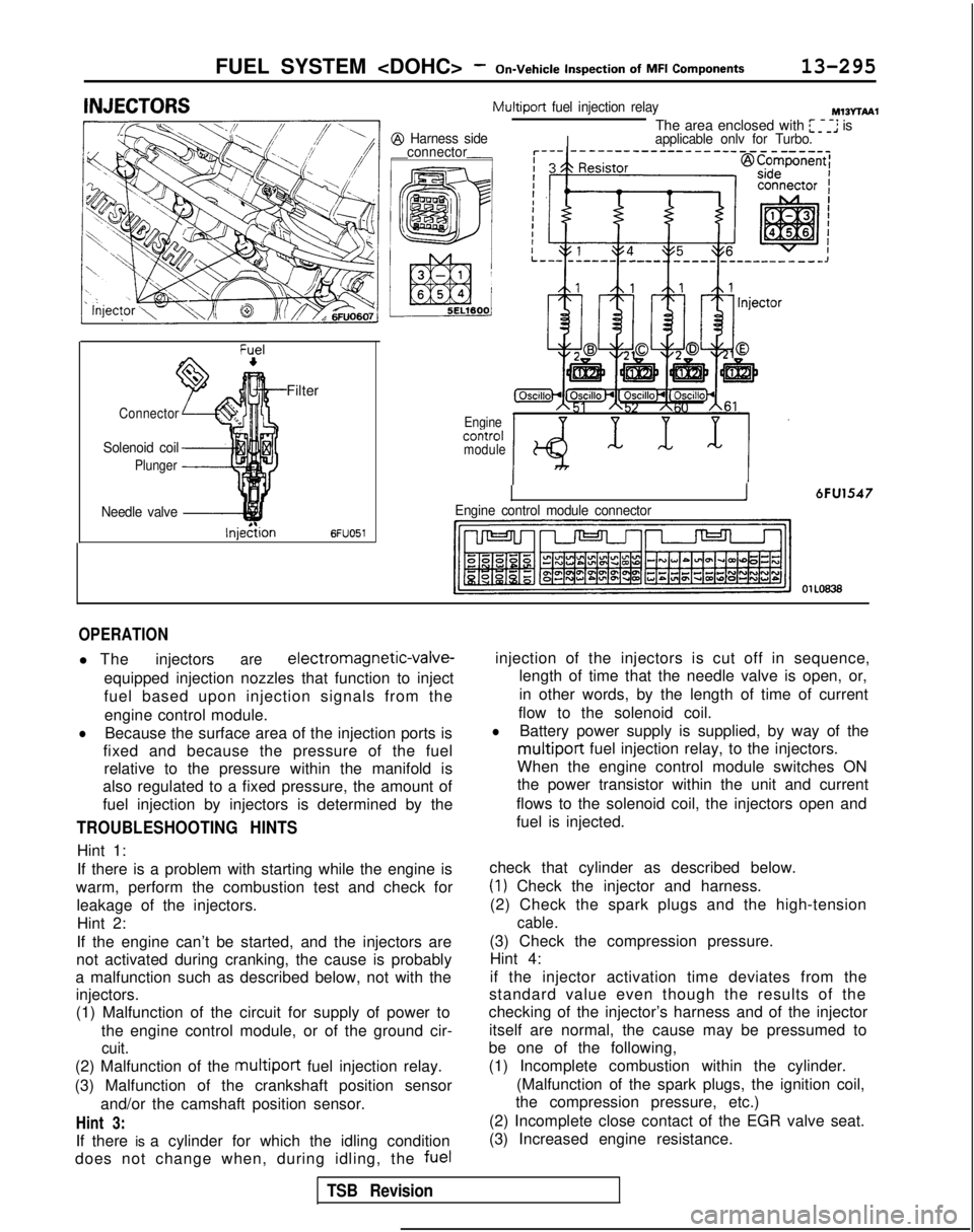
OPERATION
l The injectorsare electromagnetic-valve-
equipped injection nozzles that function to inject
fuel based upon injection signals from the engine control module.
lBecause the surface area of the injection ports is
fixed and because the pressure of the fuel relative to the pressure within the manifold is
also regulated to a fixed pressure, the amount of
fuel injection by injectors is determined by the
TROUBLESHOOTING HINTS
Hint 1:
If there is a problem with starting while the engine is
warm, perform the combustion test and check for leakage of the injectors.Hint 2:
If the engine can’t be started, and the injectors are
not activated during cranking, the cause is probably
a malfunction such as described below, not with the injectors.
(1) Malfunction of the circuit for supply of power to
the engine control module, or of the ground cir-
cuit.
(2) Malfunction of the multiport fuel injection relay.
(3) Malfunction of the crankshaft position sensor and/or the camshaft position sensor.
Hint 3:
If there is a cylinder for which the idling condition
does not change when, during idling, the fuelinjection of the injectors is cut off in sequence,
length of time that the needle valve is open, or,
in other words, by the length of time of current
flow to the solenoid coil.
lBattery power supply is supplied, by way of the
multiport fuel injection relay, to the injectors.
When the engine control module switches ON
the power transistor within the unit and current
flows to the solenoid coil, the injectors open and
fuel is injected.
check that cylinder as described below.
(1) Check the injector and harness.
(2) Check the spark plugs and the high-tension
cable.
(3) Check the compression pressure. Hint 4:
if the injector activation time deviates from the
standard value even though the results of the
checking of the injector’s harness and of the injector
itself are normal, the cause may be pressumed to
be one of the following,
(1) Incomplete combustion within the cylinder.
(Malfunction of the spark plugs, the ignition coil,
the compression pressure, etc.)
(2) Incomplete close contact of the EGR valve seat.
(3) Increased engine resistance.
TSB Revision
Page 440 of 1273
131298FUEL SYSTEM
of
MFI Components
E 0,-I3
4
El00
RESISTOR
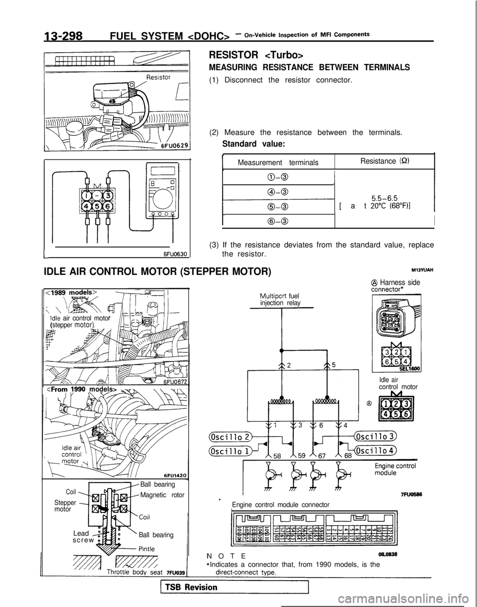
MEASURING RESISTANCE BETWEEN TERMINALS
(1) Disconnect the resistor connector.
(2) Measure the resistance between the terminals.
Standard value:
Measurement terminals Resistance (52)
O-0I
1-1 [at %$%&)I
t@-0I
(3) If the resistance deviates from the standard value, replace
L6FUO630the resistor.
IDLE AIR CONTROL MOTOR (STEPPER MOTOR)
Idle air control motor(stepper motor)
-~~~~:Froty
?990models>\\ v-,
6FU142(
Coil
Steppermotor Ball bearing
Magnetic rotor
Ball bearing
Pintle
Lead z
1screw 0
Multiport fuel
injection relay
--l-
MlJYUAH
1 Harness sidelnnector”
.Engine control module connectorII
NOT
E
olLos3s
*: Indicates a connector that, from 1990 models, is the
7FUO586
Idle aircontrol motor
Page 441 of 1273
FUEL SYSTEM
MFI Components13-299
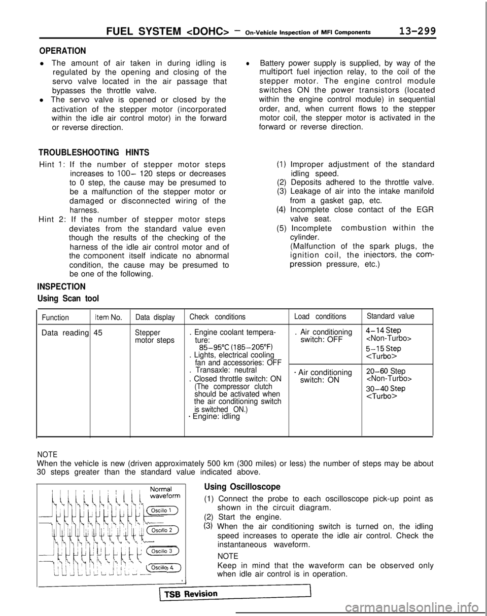
OPERATION
l The amount of air taken in during idling is
regulated by the opening and closing of the
servo valve located in the air passage that
bypasses the throttle valve.
l The servo valve is opened or closed by the
activation of the stepper motor (incorporated
within the idle air control motor) in the forward
or reverse direction.
TROUBLESHOOTING HINTS
Hint 1: If the number of stepper motor steps increases to
IOO- 120 steps or decreases
to 0 step, the cause may be presumed to be a malfunction of the stepper motor or
damaged or disconnected wiring of the
harness.
Hint 2: If the number of stepper motor steps
deviates from the standard value even
though the results of the checking of the
harness of the idle air control motor and of
the comoonent
itself indicate no abnormal
condition, the cause may be presumed to be one of the following.
INSPECTION
Using Scan tool
lBattery power supply is supplied, by way of the
multiport fuel injection relay, to the coil of the
stepper motor. The engine control module
switches ON the power transistors (located
within the engine control module) in sequential
order, and, when current flows to the stepper motor coil, the stepper motor is activated in the
forward or reverse direction.
(1) Improper adjustment of the standard
idling speed.
(2) Deposits adhered to the throttle valve.
(3) Leakage of air into the intake manifold
from a gasket gap, etc.
(4) Incomplete close contact of the EGRvalve seat.
(5) Incomplete combustion within the
cylinder.
(Malfunction of the spark plugs, the
ignition coil, the iniectors,
the
com- pression
pressure, etc.)
FunctionItem No.Data display Check conditions Load conditionsStandard value
Data reading 45Steppermotor steps. Engine coolant tempera-
. Air conditioning
4-14Step
ture:switch: OFF
(185-205°F)
. Lights, electrical cooling
:$b::pfan and accessories: OFF
. Transaxle: neutral
. Closed throttle switch: ON
- Air conditioning 20-60 Step
switch: ON
(The compressor clutchshould be activated when
the air conditioning switch;J-;;o~P
is switched ON.)* Engine: idling
1;:!,1;:!,
/!-I\/!-I\
f$&$:”f$&$:”
! ,‘,! ,‘,
4);4);
;jj\(Q(j!jGZ-);jj\(Q(j!jGZ-)
lili
q#Q~Hq#Q~HF]F]
ii 2 L J 2 L ~ -0SClllO 4ii 2 L J 2 L ~ -0SClllO 4
NOTE
When the vehicle is new (driven approximately 500 km (300 miles) or l\
ess) the number of steps may be about
30 steps greater than the standard value indicated above.
Using Oscilloscope
(1) Connect the probe to each oscilloscope pick-up point as
shown in the circuit diagram.
(2) Start the engine.
(3) When the air conditioning switch is turned on, the idling speed increases to operate the idle air control. Check theinstantaneous waveform.
NOTE
Keep in mind that the waveform can be observed only
when idle air control is in operation.
Page 449 of 1273
FUEL SYSTEM
On-Vehicle
Inspection
of MFI
Components13-307
Harness side
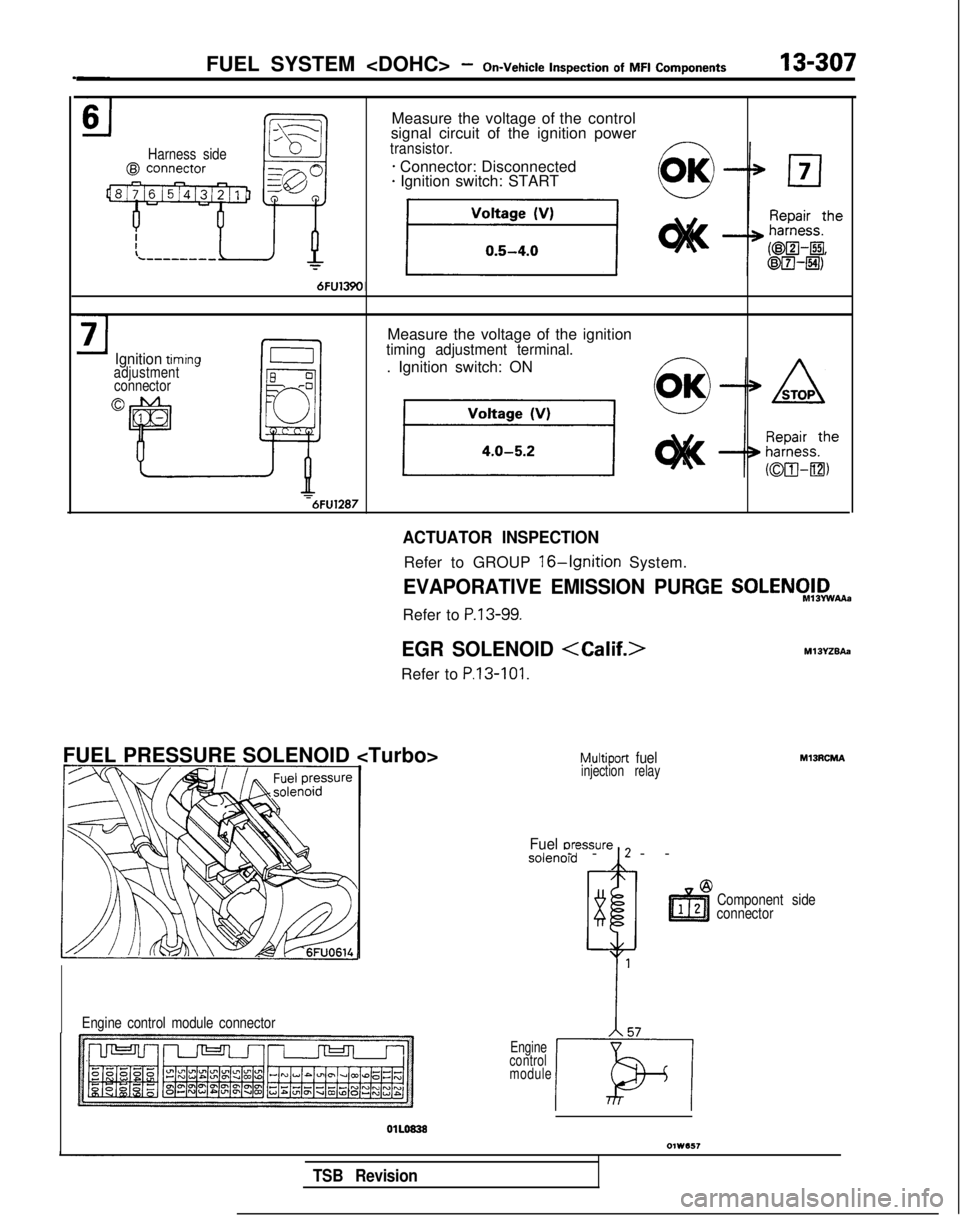
Measure the voltage of the control
signal circuit of the ignition power
transistor.
* Connector: Disconnected* Ignition switch: START
Ignition timrngadjustment connector
0
Measure the voltage of the ignitiontiming adjustment terminal.
. Ignition switch: ON =6FU1287
FUEL PRESSURE SOLENOID
Engine control module connector
ACTUATOR INSPECTION
Refer to GROUP 16-Ignition System.
EVAPORATIVE EMISSION PURGE SOLENCI!,D,,.
Refer to P.13-99.
EGR SOLENOID
Refer to P.13-101.
Multiport fuelinjection relay
--I-
-
Fuel uressure , 2
Component side
connector
Engine
control
module
TSB Revision
Page 450 of 1273
13-308FUEL SYSTEM
of
MFI
Components
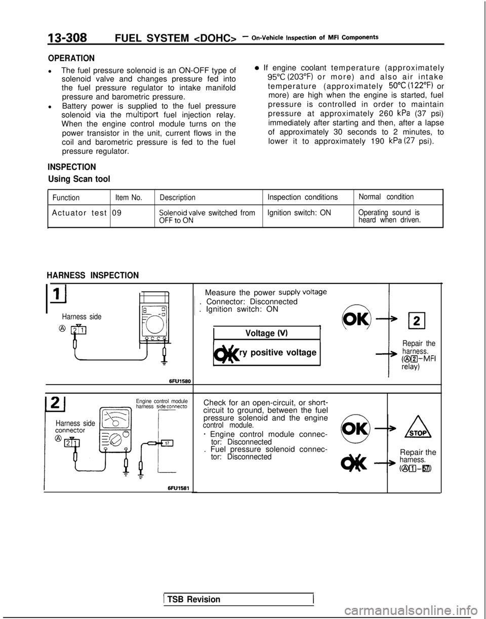
OPERATION
l
The fuel pressure solenoid is an ON-OFF type of
solenoid valve and changes pressure fed into
the fuel pressure regulator to intake manifold
pressure and barometric pressure.
l Battery power is supplied to the fuel pressure
solenoid via the multiport
fuel injection relay.
When the engine control module turns on the
power transistor in the unit, current flows in the
coil and barometric pressure is fed to the fuel pressure regulator.
INSPECTION
Using Scan tool
0 If engine coolant temperature (approximatel
y
95°C (203°F) or more) and also air intake
temperature (approximately
50°C (122°F) or
more) are high when the engine is started, fuel
pressure is controlled in order to maintain
pressure at approximately 260
kPa (37 psi)
immediately after starting and then, after a lapse
of approximately 30 seconds to 2 minutes, to lower it to approximately 190
kPa (27 psi).
Function Item No.
Actuator test 09
DescriptionInspection conditionsNormal condition
$$;;i;;;alve switched fromIgnition switch: ONOperating sound is
heard when driven.
HARNESS INSPECTION
Harness side
Measure the power supply VokW 1
. Connector: Disconnected 1
. Ignition switch: ON
Voltage 04
1 Battery positive voltage 1t)lt<
02
Repair theharness.
@I4,MFI
Engine control module
harness side connecto
Harness side
Check for an open-circuit, or shot-t-circuit to ground, between the fuel
pressure solenoid and the engine
control module.
- Engine control module connec-tor: Disconnected. Fuel pressure solenoid connec-tor: DisconnectedRepair theharness.
h25xwzl21,
1 TSB Revision
Page 451 of 1273
FUEL SYSTEM
Inspection
of
MFI Components13-309
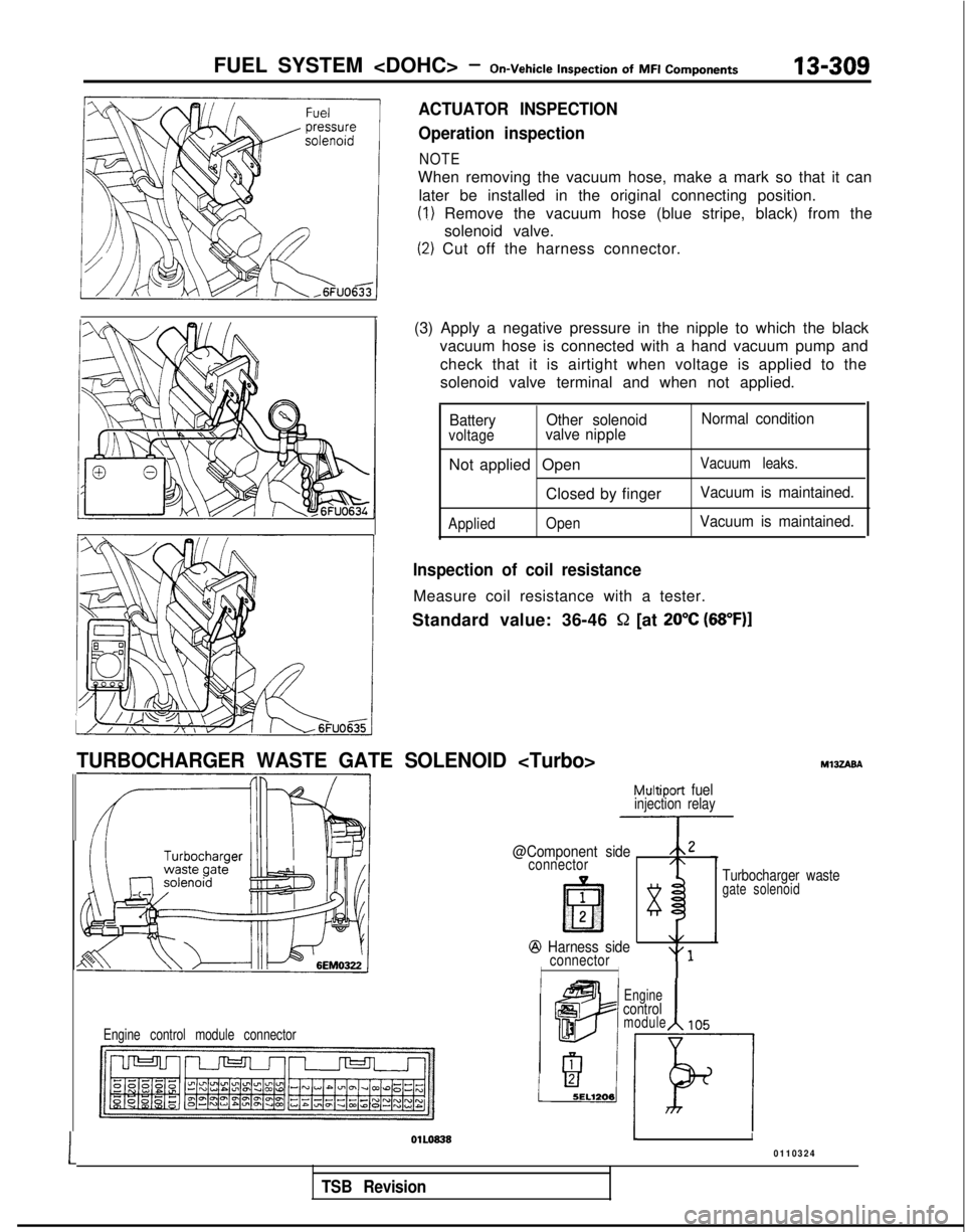
ACTUATOR INSPECTION
Operation inspection
NOTE
When removing the vacuum hose, make a mark so that it can
later be installed in the original connecting position.
(1) Remove the vacuum hose (blue stripe, black) from the solenoid valve.
(2) Cut off the harness connector.
(3) Apply a negative pressure in the nipple to which the black vacuum hose is connected with a hand vacuum pump and
check that it is airtight when voltage is applied to the
solenoid valve terminal and when not applied.
Battery Other solenoid Normal conditionvoltagevalve nipple
Not applied OpenVacuum leaks.
Closed by fingerVacuum is maintained.
Applied
OpenVacuum is maintained.
Inspection of coil resistance
Measure coil resistance with a tester.
Standard value: 36-46
S2 [at 20°C (68”F)I
TURBOCHARGER WASTE GATE SOLENOID
Multiport fuelinjection relay
@Component side,,2
connector/\
1
lE?l283
@J Harness side\/
connector“1
II
Engine control module connector
MlJZABA
Turbocharger wastegate solenoid
Engine
control
1module105
1
OlLo8381I
0110324
TSB Revision