warning light MITSUBISHI L200 2014 Owner's Manual (in English)
[x] Cancel search | Manufacturer: MITSUBISHI, Model Year: 2014, Model line: L200, Model: MITSUBISHI L200 2014Pages: 362, PDF Size: 20.97 MB
Page 6 of 362
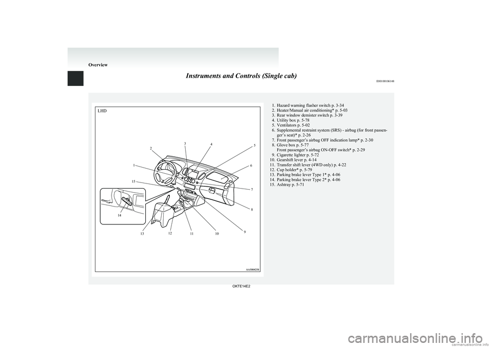
Instruments and Controls (Single cab)E001001061481. Hazard warning flasher switch p. 3-34
2. Heater/Manual air conditioning* p. 5-03
3. Rear window demister switch p. 3-39
4. Utility box p. 5-78
5. Ventilators p. 5-02
6. Supplemental restraint system (SRS) - airbag (for front passen- ger’s seat)* p. 2-26
7. Front passenger’s airbag OFF indication lamp* p. 2-30
8. Glove box p. 5-77 Front passenger’s airbag ON-OFF switch* p. 2-29
9. Cigarette lighter p. 5-72
10. Gearshift lever p. 4-14
11. Transfer shift lever (4WD only) p. 4-22
12. Cup holder* p. 5-79
13. Parking brake lever Type 1* p. 4-06
14. Parking brake lever Type 2* p. 4-06
15. Ashtray p. 5-71
Overview
OKTE14E212
3
4
5
6
78
9
10
11
12
13
14 15
LHD
Page 7 of 362
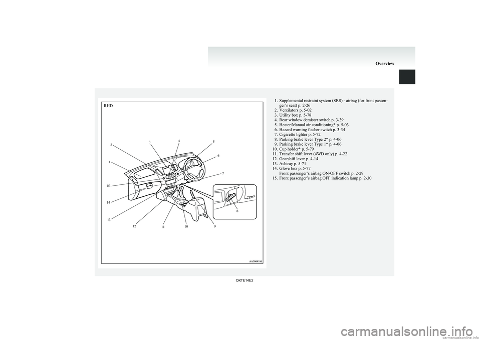
1. Supplemental restraint system (SRS) - airbag (for front passen-ger’s seat) p. 2-26
2. Ventilators p. 5-02
3. Utility box p. 5-78
4. Rear window demister switch p. 3-39
5. Heater/Manual air conditioning* p. 5-03
6. Hazard warning flasher switch p. 3-34
7. Cigarette lighter p. 5-72
8. Parking brake lever Type 2* p. 4-06
9. Parking brake lever Type 1* p. 4-06
10. Cup holder* p. 5-79
11. Transfer shift lever (4WD only) p. 4-22
12. Gearshift lever p. 4-14
13. Ashtray p. 5-71
14. Glove box p. 5-77 Front passenger’s airbag ON-OFF switch p. 2-29
15. Front passenger’s airbag OFF indication lamp p. 2-30
Overview
OKTE14E212
3
4
5
6
7
8
9
10
11
12
13
14
15
RHD
Page 8 of 362
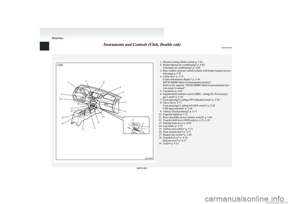
Instruments and Controls (Club, Double cab)E001001066431. Hazard warning flasher switch p. 3-34
2. Heater/Manual air conditioning* p. 5-03 Automatic air conditioning* p. 5-08
3. Rear window demister switch (vehicle with heater/manual air con-
ditioning) p. 3-39
4. Utility box* p. 5-78 Centre information display* p. 3-10
MITSUBISHI Multi-Communication System*
Refer to the separate “MITSUBISHI Multi-Communication Sys-
tem owner’s manual”
5. Ventilators p. 5-02
6. Supplemental restraint system (SRS) - airbag (for front passen- ger’s seat)* p. 2-26
7. Front passenger’s airbag OFF indication lamp* p. 2-30
8. Glove box p. 5-77 Front passenger’s airbag ON-OFF switch* p. 2-29
USB input terminal* p. 5-68
9. Ashtray (fixed position)* p. 5-71
10. Cigarette lighter p. 5-72
11. Rear retractable power window switch* p. 1-08
12. Transfer shift lever (4WD only) p. 4-22, 4-26
13. Parking brake lever p. 4-06
14. Cup holder p. 5-79
15. Ashtray (moveable)* p. 5-71
16. Front console box* p. 5-77
17. Heated seat switch* p. 2-06
18. Gearshift lever* p. 4-14 Selector lever* p. 4-17
19. Audio* p. 5-13
Overview
OKTE14E2LHD1 2
3
4
56
7
8
9
10
11
12
13
14 15 16
17 18
19
Page 9 of 362
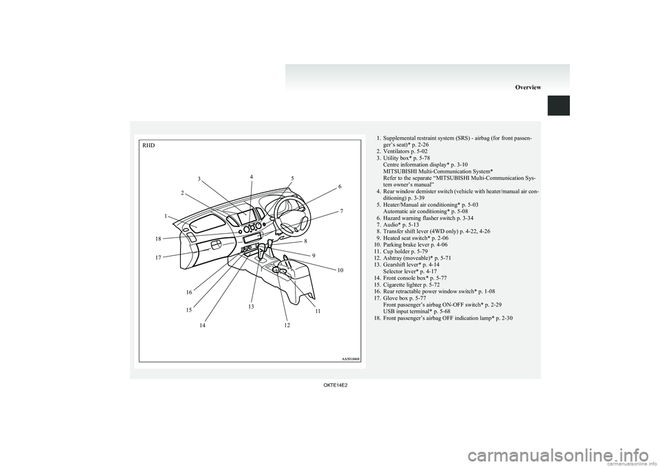
1. Supplemental restraint system (SRS) - airbag (for front passen-ger’s seat)* p. 2-26
2. Ventilators p. 5-02
3. Utility box* p. 5-78 Centre information display* p. 3-10
MITSUBISHI Multi-Communication System*
Refer to the separate “MITSUBISHI Multi-Communication Sys-
tem owner’s manual”
4. Rear window demister switch (vehicle with heater/manual air con-
ditioning) p. 3-39
5. Heater/Manual air conditioning* p. 5-03 Automatic air conditioning* p. 5-08
6. Hazard warning flasher switch p. 3-34
7. Audio* p. 5-13
8. Transfer shift lever (4WD only) p. 4-22, 4-26
9. Heated seat switch* p. 2-06
10. Parking brake lever p. 4-06
11. Cup holder p. 5-79
12. Ashtray (moveable)* p. 5-71
13. Gearshift lever* p. 4-14 Selector lever* p. 4-17
14. Front console box* p. 5-77
15. Cigarette lighter p. 5-72
16. Rear retractable power window switch* p. 1-08
17. Glove box p. 5-77 Front passenger’s airbag ON-OFF switch* p. 2-29
USB input terminal* p. 5-68
18. Front passenger’s airbag OFF indication lamp* p. 2-30
Overview
OKTE14E2RHD12
3
4
5
6
7
8 9 10
11
12
13
14
15 16
17
18
Page 32 of 362
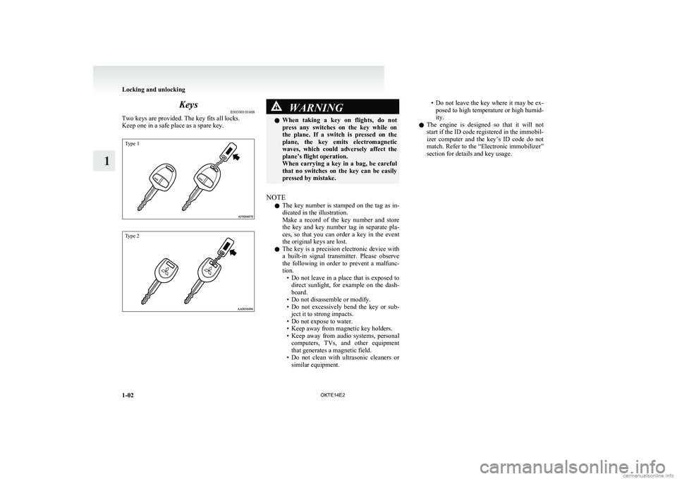
KeysE00300101608
Two keys are provided. The key fits all locks.
Keep one in a safe place as a spare key.
Type 1Type 2
WARNINGl When taking a key on flights, do not
press any switches on the key while on
the plane. If a switch is pressed on the
plane, the key emits electromagnetic
waves, which could adversely affect the
plane’s flight operation.
When carrying a key in a bag, be careful
that no switches on the key can be easily
pressed by mistake.
NOTE
l The key number is stamped on the tag as in-
dicated in the illustration.
Make a record of the key number and store
the key and key number tag in separate pla-
ces, so that you can order a key in the event
the original keys are lost.
l The key is a precision electronic device with
a built-in signal transmitter. Please observe
the following in order to prevent a malfunc-
tion. •Do not leave in a place that is exposed to
direct sunlight, for example on the dash-
board.
• Do not disassemble or modify.
• Do not excessively bend the key or sub-
ject it to strong impacts.
• Do not expose to water.
• Keep away from magnetic key holders.
• Keep away from audio systems, personal
computers, TVs, and other equipment
that generates a magnetic field.
• Do not clean with ultrasonic cleaners or
similar equipment.
• Do not leave the key where it may be ex-
posed to high temperature or high humid-
ity.
l The engine is designed so that it will not
start if the ID code registered in the immobil-
izer computer and the key’s ID code do not
match. Refer to the “Electronic immobilizer”
section for details and key usage.
Locking and unlocking
1-02 OKTE14E2
1
Page 40 of 362
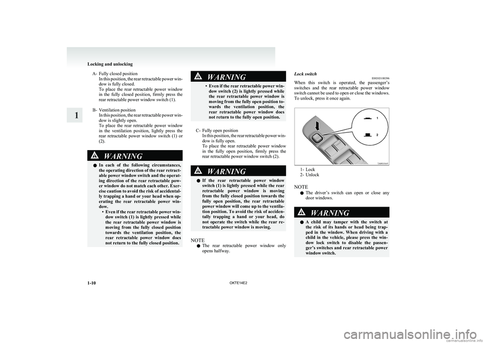
A- Fully closed positionIn this position, the rear retractable power win-
dow is fully closed.
To place the rear retractable power window
in the fully closed position, firmly press the
rear retractable power window switch (1).
B- Ventilation position In this position, the rear retractable power win-
dow is slightly open.
To place the rear retractable power window
in the ventilation position, lightly press the
rear retractable power window switch (1) or
(2).WARNINGl In each of the following circumstances,
the operating direction of the rear retract-
able power window switch and the operat-
ing direction of the rear retractable pow-
er window do not match each other. Exer-
cise caution to avoid the risk of accidental-
ly trapping a hand or your head when op-
erating the rear retractable power win-
dow. •Even if the rear retractable power win-
dow switch (1) is lightly pressed while
the rear retractable power window is
moving from the fully closed position
towards the ventilation position, the
rear retractable power window does
not return to the fully closed position.WARNING• Even if the rear retractable power win-
dow switch (2) is lightly pressed while
the rear retractable power window is
moving from the fully open position to-
wards the ventilation position, the
rear retractable power window does
not return to the fully open position.
C- Fully open position In this position, the rear retractable power win-
dow is fully open.
To place the rear retractable power window
in the fully open position, firmly press the
rear retractable power window switch (2).
WARNINGl If the rear retractable power window
switch (1) is lightly pressed while the rear
retractable power window is moving
from the fully closed position towards the
fully open position, the rear retractable
power window will come up to the ventila-
tion position. To avoid the risk of acciden-
tally trapping a hand or your head, do
not operate the switch while the rear re-
tractable power window is moving.
NOTE
l The rear retractable power window only
opens halfway.
Lock switch E00303100396
When this switch is operated, the passenger’s
switches and the rear retractable power window
switch cannot be used to open or close the windows.
To unlock, press it once again.
1- Lock
2- Unlock
NOTE l The driver’s switch can open or close any
door windows.
WARNINGl A child may tamper with the switch at
the risk of its hands or head being trap-
ped in the window. When driving with a
child in the vehicle, please press the win-
dow lock switch to disable the passen-
ger’s switches and rear retractable power
window switch.
Locking and unlocking
1-10 OKTE14E2
1
Page 56 of 362
WARNINGlNo modifications or additions should be
made by the user which will either pre-
vent the seat belt adjusting devices from
operating to remove slack, or prevent the
seat belt assembly from being adjusted to
remove slack.
l To reduce risk of serious or fatal injury
in an accident, including the deploying
driver’s airbag, adjust the driver’s seat
as far back as possible while maintaining
a position that still allows good visibility
and good control of the steering wheel,
the brake and accelerator, and vehicle con-
trols.
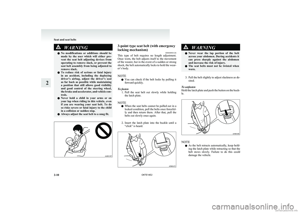
l Never hold a child in your arms or on
your lap when riding in this vehicle, even
if you are wearing your seat belt. To do
so risks severe or fatal injury to the child
in a collision or sudden stop.
l Always adjust the seat belt to a snug fit.3-point type seat belt (with emergency
locking mechanism) E00404901126
This type of belt requires no length adjustment.
Once worn, the belt adjusts itself to the movement
of the wearer, but in the event of a sudden or strong
shock, the belt automatically locks to hold the wear-
er’s body.
NOTE l You can check if the belt locks by pulling it
forward quickly.
To fasten 1.Pull the seat belt out slowly while holding
the latch plate.
NOTE l When the seat belts cannot be pulled out in a
locked condition, pull the belts once forceful-
ly and then return them. After that, pull the
belts out slowly once again.
2. Insert the latch plate into the buckle until a
“click” is heard.WARNINGl Never wear the lap portion of the belt
across your abdomen. During accidents it
can press sharply against the abdomen
and increase the risk of injury.
l The seat belts must not be twisted when
worn.
3. Pull the belt slightly to adjust slackness as de-
sired.
To unfasten
Hold the latch plate and push the button on the buck-
le.
NOTE
l As the belt retracts automatically, keep hold-
ing the latch plate while retracting so that the
belt stows slowly. Failure to do this could
damage the vehicle.
Seat and seat belts
2-10 OKTE14E2
2
Page 75 of 362
The airbags will operate only when the ignition
switch is in the “ON” or “START” position.
When the airbag control unit detect an impact of suf-
ficient frontal or side force, it sends an ignition sig-
nal to the airbag modules to ignite materials in the
inflator and generate gas and inflate the airbags.
The airbags deployment produces a sudden, loud
noise, and releases some smoke and powder, but
these conditions are not injurious, and do not indi-
cate a fire in the vehicle. People with respiratory
problems may feel some temporary irritation from
chemicals used to produce the deployment; open
the windows after airbag deployment, if safe to do
so.
The airbags deflate very rapidly after deployment,
so there is little danger of obscured vision.
The time required from the sensors detecting an im-
pact to deflation of the airbags after deployment is
shorter than a blink of an eye.CAUTIONl Airbags inflate at an extremely rapid
speed. In certain situations, contact with
inflating airbags can result in abrasions,
light cuts, bruises, and the like.Front passenger’s airbag ON-OFF
switch E00410100331
The front passenger’s airbag ON-OFF switch can
be used to disable the front passenger’s airbag. If
you have a rearward facing child restraint system
that cannot be fitted to any seat other than the front
passenger seat, be sure to turn OFF the front passen-
ger’s airbag ON-OFF switch before using it. (Refer
to “To turn an airbag off” on page 2-29.)
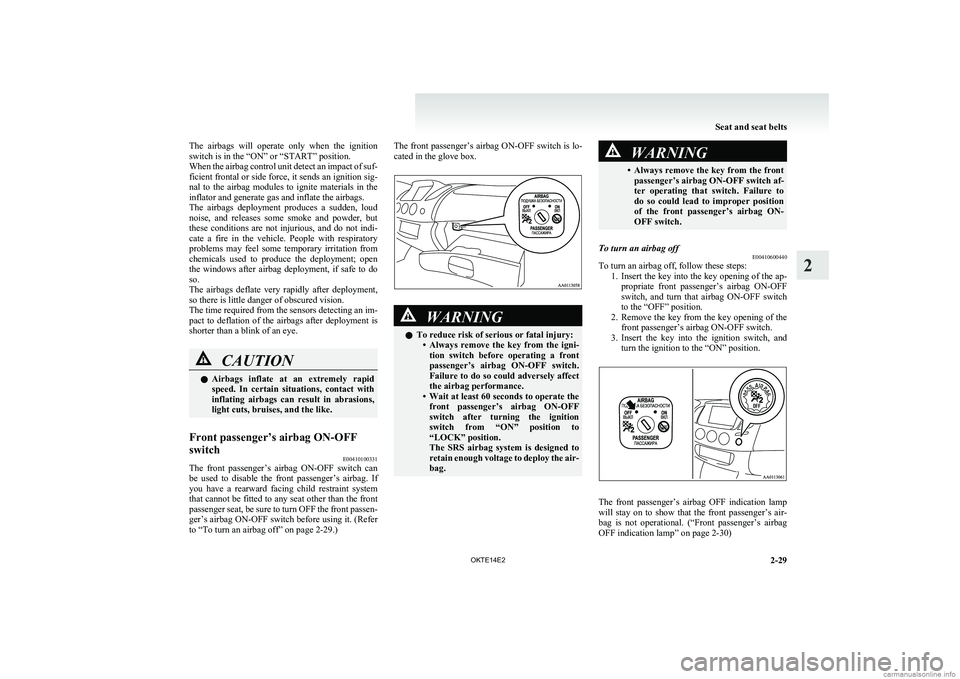
The front passenger’s airbag ON-OFF switch is lo-
cated in the glove box.WARNINGl To reduce risk of serious or fatal injury:
•Always remove the key from the igni-
tion switch before operating a front
passenger’s airbag ON-OFF switch.
Failure to do so could adversely affect
the airbag performance.
• Wait at least 60 seconds to operate the
front passenger’s airbag ON-OFF
switch after turning the ignition
switch from “ON” position to
“LOCK” position.
The SRS airbag system is designed to
retain enough voltage to deploy the air-
bag.WARNING• Always remove the key from the front
passenger’s airbag ON-OFF switch af-
ter operating that switch. Failure to
do so could lead to improper position
of the front passenger’s airbag ON-
OFF switch.To turn an airbag off E00410600440
To turn an airbag off, follow these steps:
1.Insert the key into the key opening of the ap-
propriate front passenger’s airbag ON-OFF
switch, and turn that airbag ON-OFF switch
to the “OFF” position.
2. Remove the key from the key opening of the
front passenger’s airbag ON-OFF switch.
3. Insert the key into the ignition switch, and
turn the ignition to the “ON” position.
The front passenger’s airbag OFF indication lamp
will stay on to show that the front passenger’s air-
bag is not operational. ( “Front passenger’s airbag
OFF indication lamp” on page 2-30)
Seat and seat belts
2-29
OKTE14E2
2
Page 88 of 362
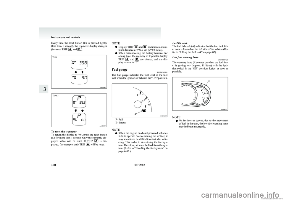
Every time the reset button (C) is pressed lightly
(less than 1 second), the tripmeter display changes
(between TRIP
and ).
Type 1Type 2
To reset the tripmeter
To return the display to “0”, press the reset button
(C) for more than 1 second. Only the currently dis-
played value will be reset. If TRIP
is dis-
played, for example, only TRIP will be reset.
NOTE
l Display TRIP
and each have a maxi-
mum distance of 999.9 km (999.9 miles).
l When disconnecting the battery terminal for
a long time, the memory of tripmeter display
TRIP
and are cleared, and the dis-
play returns to “0”.
Fuel gauge E00500700902
The fuel gauge indicates the fuel level in the fuel
tank when the ignition switch is in the “ON” position.
F- Full
E- Empty
NOTE l When the engine on diesel-powered vehicles
fails to operate due to running out of fuel, it
may sometimes be difficult to start after refu-
eling. This is due to air entering the fuel sys-
tem. Therefore, air must be bled from the sys-
tem. (Refer to “Bleeding the fuel system” on
page 6-05.)
Fuel lid mark
The fuel lid mark (A) indicates that the fuel tank fill-
er door is located on the left side of the vehicle (Re-
fer to “Filling the fuel tank” on page 02).Low fuel warning lamp E00508100739
The warning lamp (A) comes on when the fuel lev-
el is getting low (approx. 11 litres) with the igni-
tion switch in the “ON” position. Refuel as soon as
possible.
NOTE
l On inclines or curves, due to the movement
of fuel in the tank, the low fuel warning lamp
may indicate incorrectly.
Instruments and controls
3-04 OKTE14E2
3
Page 91 of 362
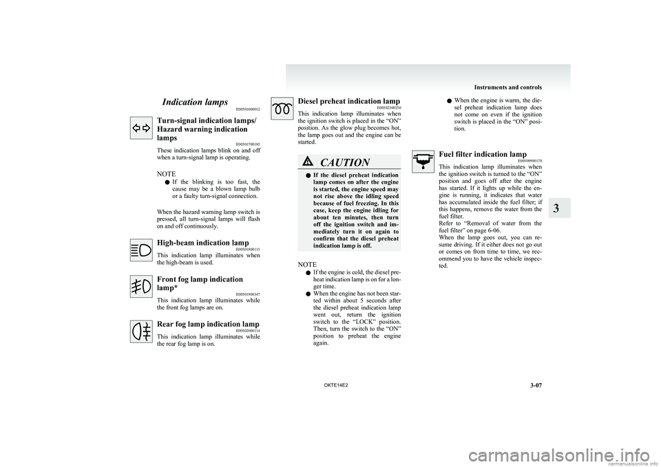
Indication lampsE00501600012Turn-signal indication lamps/
Hazard warning indication
lamps E00501700185
These indication lamps blink on and off
when a turn-signal lamp is operating.
NOTE l If the blinking is too fast, the
cause may be a blown lamp bulb
or a faulty turn-signal connection.
When the hazard warning lamp switch is
pressed, all turn-signal lamps will flash
on and off continuously.High-beam indication lamp E00501800115
This indication lamp illuminates when
the high-beam is used.Front fog lamp indication
lamp* E00501900347
This indication lamp illuminates while
the front fog lamps are on.Rear fog lamp indication lamp E00502000114
This indication lamp illuminates while
the rear fog lamp is on.Diesel preheat indication lamp E00502300250
This indication lamp illuminates when
the ignition switch is placed in the “ON”
position. As the glow plug becomes hot,
the lamp goes out and the engine can be
started.CAUTIONl If the diesel preheat indication
lamp comes on after the engine
is started, the engine speed may
not rise above the idling speed
because of fuel freezing. In this
case, keep the engine idling for
about ten minutes, then turn
off the ignition switch and im-
mediately turn it on again to
confirm that the diesel preheat
indication lamp is off.
NOTE
l If the engine is cold, the diesel pre-
heat indication lamp is on for a lon-
ger time.
l When the engine has not been star-
ted within about 5 seconds after
the diesel preheat indication lamp
went out, return the ignition
switch to the “LOCK” position.
Then, turn the switch to the “ON”
position to preheat the engine
again.
l When the engine is warm, the die-
sel preheat indication lamp does
not come on even if the ignition
switch is placed in the “ON” posi-
tion.Fuel filter indication lamp E00509900170
This indication lamp illuminates when
the ignition switch is turned to the “ON”
position and goes off after the engine
has started. If it lights up while the en-
gine is running, it indicates that water
has accumulated inside the fuel filter; if
this happens, remove the water from the
fuel filter.
Refer to “Removal of water from the
fuel filter” on page 6-06.
When the lamp goes out, you can re-
sume driving. If it either does not go out
or comes on from time to time, we rec-
ommend you to have the vehicle inspec-
ted.
Instruments and controls
3-07
OKTE14E2
3