key MITSUBISHI L200 2015 (in English) Workshop Manual
[x] Cancel search | Manufacturer: MITSUBISHI, Model Year: 2015, Model line: L200, Model: MITSUBISHI L200 2015Pages: 418, PDF Size: 25.8 MB
Page 268 of 418
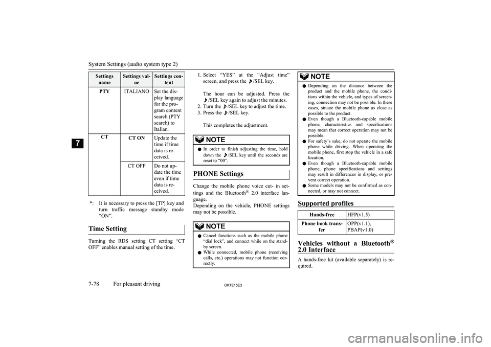
SettingsnameSettings val- ueSettings con-tentPTYITALIANOSet the dis-
play language
for the pro-
gram content
search (PTY
search) to
Italian.CTCT ONUpdate the
time if time
data is re-
ceived.CT OFFDo not up-
date the time
even if time
data is re-
ceived.*:It is necessary to press the [TP] key and
turn traffic message standby mode “ON”.
Time Setting
Turning the RDS setting CT setting “CT
OFF” enables manual setting of the time.
1. Select “YES” at the “Adjust time”
screen, and press the
/SEL key.
The hour can be adjusted. Press the
/SEL key again to adjust the minutes.
2. Turn the
/SEL key to adjust the time.
3. Press the
/SEL key.
This completes the adjustment.
NOTEl In order to finish adjusting the time, hold
down the /SEL key until the seconds are
reset to “00”.
PHONE Settings
Change the mobile phone voice cut- in set-
tings and the Bluetooth ®
2.0 interface lan-
guage.
Depending on the vehicle, PHONE settings
may not be possible.
NOTEl Cancel functions such as the mobile phone
“dial lock”, and connect while on the stand- by screen.
l While connected, mobile phone (receiving
calls, etc.) operations may not function cor- rectly.NOTEl Depending on the distance between the
product and the mobile phone, the condi- tions within the vehicle, and types of screen-ing, connection may not be possible. In thesecases, situate the mobile phone as close as possible to the product.
l Even though a Bluetooth-capable mobile
phone, characteristics and specifications
may mean that correct operation may not be possible.
l For safety’s sake, do not operate the mobile
phone while driving. When operating the mobile phone, first stop the vehicle in a safe location.
l Even though a Bluetooth-capable mobile
phone, phone specifications and settings may result in differences in display, or pre-vent correct operation.
l Some models may not be confirmed as con-
nected, or may not connect.
Supported profiles
Hands-freeHFP(v1.5)Phone book trans-
ferOPP(v1.1),
PBAP(v1.0)
Vehicles without a Bluetooth ®
2.0 Interface
A hands-free kit (available separately) is re- quired.
System Settings (audio system type 2)
7-78OKTE15E3For pleasant driving7
Page 269 of 418
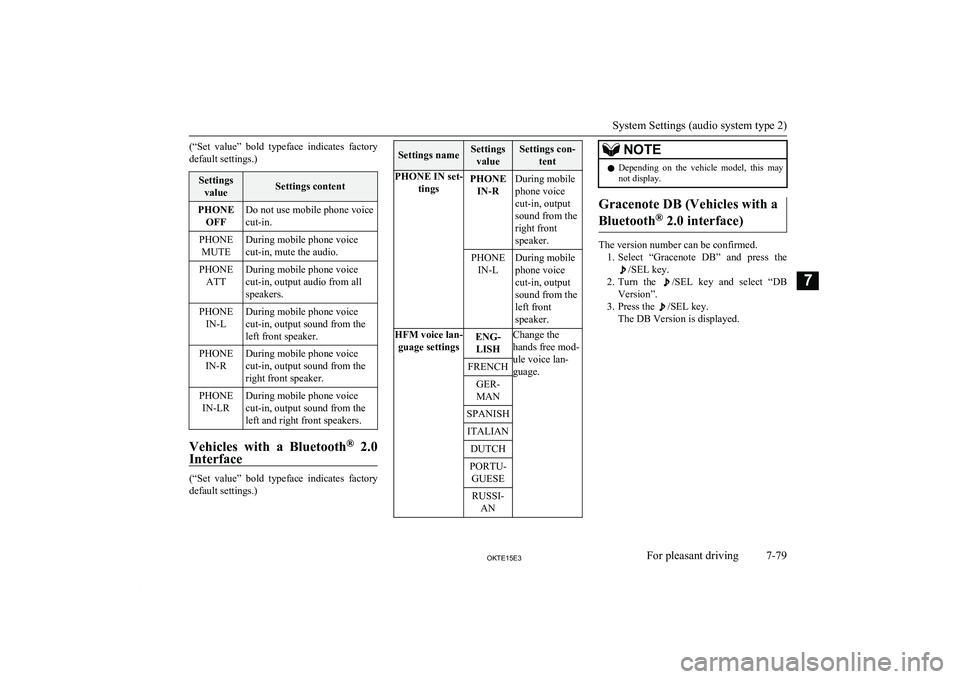
(“Set value” bold typeface indicates factory
default settings.)Settings valueSettings contentPHONE OFFDo not use mobile phone voice
cut-in.PHONE MUTEDuring mobile phone voice
cut-in, mute the audio.PHONE ATTDuring mobile phone voice
cut-in, output audio from all
speakers.PHONE IN-LDuring mobile phone voice
cut-in, output sound from the
left front speaker.PHONE IN-RDuring mobile phone voice
cut-in, output sound from the
right front speaker.PHONE IN-LRDuring mobile phone voice
cut-in, output sound from the
left and right front speakers.
Vehicles with a Bluetooth ®
2.0
Interface
(“Set value” bold typeface indicates factory
default settings.)
Settings nameSettings
valueSettings con- tentPHONE IN set- tingsPHONEIN-RDuring mobile
phone voice
cut-in, output
sound from the
right front
speaker.PHONE IN-LDuring mobile
phone voice
cut-in, output
sound from the
left front
speaker.HFM voice lan- guage settingsENG-LISHChange the
hands free mod-
ule voice lan-
guage.FRENCHGER-
MANSPANISHITALIANDUTCHPORTU- GUESERUSSI- ANNOTEl Depending on the vehicle model, this may
not display.
Gracenote DB (Vehicles with a
Bluetooth ®
2.0 interface)
The version number can be confirmed.
1. Select “Gracenote DB” and press the
/SEL key.
2. Turn the
/SEL key and select “DB
Version”.
3. Press the
/SEL key.
The DB Version is displayed.
System Settings (audio system type 2)
7-79OKTE15E3For pleasant driving7
Page 281 of 418
NOTElIf 7 devices have already been paired, the
voice guide will say “Maximum devicespaired” and then the system will end the
pairing process. To register a new device, delete one device and then repeat the pairing
process.
(Refer to “Deleting a device” on page 7-92.)
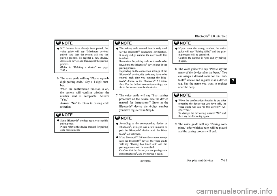
6. The voice guide will say “Please say a 4-
digit pairing code.” Say a 4-digit num- ber.
When the confirmation function is on, the system will confirm whether the
number said is acceptable. Answer
“Yes.”
Answer “No” to return to pairing code selection.
NOTEl Some Bluetooth ®
devices require a specific
pairing code.
Please refer to the device manual for pairing
code requirements.NOTEl The pairing code entered here is only used
for the Bluetooth ®
connection certification.
It is any 4-digit number the user would like
to select.
Remember the pairing code as it needs to be
keyed into the Bluetooth ®
device later in the
pairing process.
Depending on the connection settings of the
Bluetooth ®
device, this code may have to be
entered each time you connect the Blue-
tooth ®
device to the Bluetooth ®
2.0 inter-
face. For the default connection settings, re-
fer to the instructions for the device.
7. The voice guide will say “Start pairing
procedure on the device. See the device manual for instructions.” Enter in the
Bluetooth ®
device the 4-digit number
you have registered in Step 6.
NOTEl According to the corresponding device to
Bluetooth ®
, it might take a few minutes to
pair the Bluetooth ®
device with the Blue-
tooth ®
2.0 interface.
l If the Bluetooth ®
2.0 interface cannot recog-
nize the Bluetooth ®
device, the voice guide
will say “Pairing has timed out” and the pairing process will be cancelled.
Confirm that the device you are pairing sup-
ports Bluetooth ®
, and try pairing it again.NOTEl If you enter the wrong number, the voice
guide will say “Pairing failed” and the pair-
ing process will be cancelled.
Confirm the number is right, and try pairing it again.
8. The voice guide will say “Please say the
name of the device after the beep.” You
can assign a desired name for the Blue-
tooth ®
device and register it as a device
tag. Say the name you want to register
after the beep.
NOTEl When the confirmation function is on, after
repeating the device tag you have said, the
voice guide will ask “Is this correct?” An-
swer “Yes.”
To change the device tag, answer “No” and then say the device tag again.
9. The voice guide will say “Pairing com-
plete,” after which a beep will be played
and the pairing process will end.
Bluetooth ®
2.0 interface
7-91OKTE15E3For pleasant driving7
Page 301 of 418
![MITSUBISHI L200 2015 (in English) Workshop Manual 2
(
) -
[Vehicles without central door locks system]
The room lamp goes on when a
door is opened. When all doors
are closed, the room lamp is illu-
minated and dimmed gradually for 7 MITSUBISHI L200 2015 (in English) Workshop Manual 2
(
) -
[Vehicles without central door locks system]
The room lamp goes on when a
door is opened. When all doors
are closed, the room lamp is illu-
minated and dimmed gradually for 7](/img/19/34877/w960_34877-300.png)
2
(
) -
[Vehicles without central door locks system]
The room lamp goes on when a
door is opened. When all doors
are closed, the room lamp is illu-
minated and dimmed gradually for 7 seconds then goes out.
However, the lamp goes out im- mediately without being dim-
med when the ignition switch is
turned to the “ON” position.
[Vehicles with central door
locks system]
The room lamp goes on when a
door is opened. When all doors
are closed, the room lamp is illu-
minated and dimmed gradually for 15 seconds then goes out.
However, the lamp goes out im- mediately without being dim-
med in case of the followings:
l All doors are closed and the
ignition switch is turned to the “ON” position.
l All doors are locked using
the key mechanism of the driver’s door, the lock knob
of the driver’s door, or the
remote control switch of the
keyless entry system (if so equipped). NOTEl On vehicles with keyless en-
try system, when the ignition
key is removed with the doors
closed, the lamp is illuminated
and after about 15 seconds it goes off.
The dimming period is also adjustable.
For further information, we
recommend you to consult a
MITSUBISHI MOTORS Au-
thorized Service Point.3
(OFF/
)
-
The lamp goes off.
Personal lamps*
E00712500156
Push the switch (A) to turn on the lamp. Push it again to turn it off.
Door courtesy lamps*
E00717500034
Each door courtesy lamp comes on when the
relevant door is opened and goes off when
the door is closed.
Centre console downlight
E00733300043
The centre console downlight go on when the lamp switch is in the “
” or the “” posi-
tion.
Interior lamps
7-111OKTE15E3For pleasant driving7
Page 303 of 418

Type 1
To open, pull the lever (A).
Type 2
The glove box can be locked and unlocked
using the key.
1- To lock
2- To unlock
3- To open, pull the lever
Front console box*
E00733400161
To open, pull up the knob (A).
Floor console box*
E00723302073
Type 1
To open, raise the lid.
Type 2
Upper and lower boxes are located inside the
floor console box.
The floor console box can also be used as an armrest.
1- Upper box
2- Lower box
NOTEl The Auxiliary Audio connector (RCA) is lo-
cated in the lower box (if so equipped). For details, refer to “To use the external audio
input function” on page 7-43 or refer to “Use
AUX” on page 7-74.
Storage spaces
7-113OKTE15E3For pleasant driving7
Page 321 of 418
To use the jack handle (Clubcab, Double cab with rear re-tractable power window only)
E00802400124
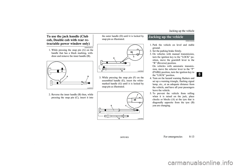
1. While pressing the snap pin (A) on the
handle that has a black marking, with-draw and remove the inner handle (B).
2. Reverse the inner handle (B) then, while
pressing the snap pin (C), insert it into
the outer handle (D) until it is locked by
snap pin as illustrated.
3. While pressing the snap pin (F) on the
assembled handle (E), insert the white-
marked handle (G) until it is locked by snap pin as illustrated.
Jacking up the vehicle
E00801002606
1. Park the vehicle on level and stable
ground.
2. Set the parking brake firmly.
3. On vehicles with manual transmission,
turn the ignition key to the “LOCK” po-
sition, move the gearshift lever to the “R” (Reverse) position.
On vehicles with automatic transmis- sion, move the selector lever to the “P” (PARK) position, turn the ignition key tothe “LOCK” position.
4. Turn on the hazard warning flashers and
set up a warning triangle, flashing signal lamp, etc., at an adequate distance from
the vehicle, and have all your passengers
leave the vehicle.
5. To prevent the vehicle from rolling
when it is raised on the jack, place
chocks or blocks (A) at the tyre that is diagonally opposite from the tyre (B)
you are changing.
Jacking up the vehicle
8-13OKTE15E3For emergencies8
Page 327 of 418
3.On vehicles with manual transmission,
turn the ignition key to the “LOCK” po-
sition, move the gearshift lever to the “R” (Reverse) position.
On vehicles with automatic transmis- sion, move the selector lever to the “P” (PARK) position, turn the ignition key to
the “LOCK” position.
4. Turn on the hazard warning flashers and
set up a warning triangle, flashing signal lamp, etc., at an adequate distance from
the vehicle, and have all your passengers
leave the vehicle.
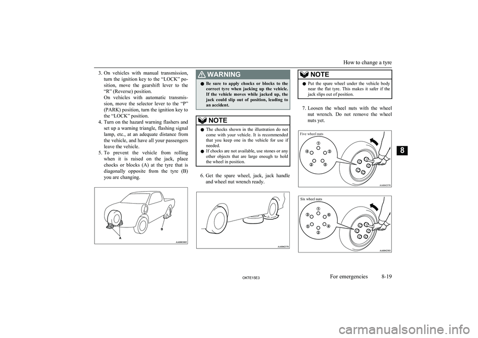
5. To prevent the vehicle from rolling
when it is raised on the jack, place
chocks or blocks (A) at the tyre that is diagonally opposite from the tyre (B)
you are changing.WARNINGl Be sure to apply chocks or blocks to the
correct tyre when jacking up the vehicle.If the vehicle moves while jacked up, the
jack could slip out of position, leading to
an accident.NOTEl The chocks shown in the illustration do not
come with your vehicle. It is recommended
that you keep one in the vehicle for use if needed.
l If chocks are not available, use stones or any
other objects that are large enough to hold the wheel in position.
6. Get the spare wheel, jack, jack handle
and wheel nut wrench ready.
NOTEl Put the spare wheel under the vehicle body
near the flat tyre. This makes it safer if the jack slips out of position.
7. Loosen the wheel nuts with the wheel
nut wrench. Do not remove the wheel nuts yet.
Five wheel nutsSix wheel nuts
How to change a tyre
8-19OKTE15E3For emergencies8
Page 331 of 418
CAUTIONlOn 2WD vehicles, if the transmission is mal-
functioning or damaged, transport the vehi- cle with the driving wheels on a carriage (Type C, D or E) as illustrated.
l If you tow a vehicle with automatic trans-
mission with the driving wheels on the
ground (Type B) as illustrated, make sure
that the towing speed and distance given be- low are never exceeded, causing damage to the transmission.
Towing speed: 50 km/h (30 mph)
Towing distance: 50 km (30 miles)
For the towing speed and the towing dis- tance, follow the local driving laws and reg-
ulations.
Towing with front wheels off
the ground (Type B)
Place the gearshift lever in the “N” (Neutral) position (manual transmission) or the selector
lever in the “N” (NEUTRAL) position (auto- matic transmission).
Release the parking brake.
CAUTIONl Never tow an automatic transmission vehicle
with the front wheels up (and the rear wheels
on the ground) (Type B) when the automatic transmission fluid level is low. This may
cause serious and expensive damage to the
transmission.
Towing with rear wheels off the
ground (Type C)
Place the gearshift lever in the “N” (Neutral)
position (manual transmission) or the selector
lever in the “N” (NEUTRAL) position (auto- matic transmission). Turn the ignition key to
the “ACC” position and secure the steering wheel in a straight ahead position with a rope
or tie-down strap. Never place the ignition switch in the “LOCK” position when towing.
Emergency towing
If towing service is not available in an emer- gency, your vehicle may be temporarily tow-ed by a cable or chain secured to the towinghook.
If your vehicle is to be towed by another ve-
hicle, pay careful attention to the following
points.
If your vehicle is to be towed by
another vehicle
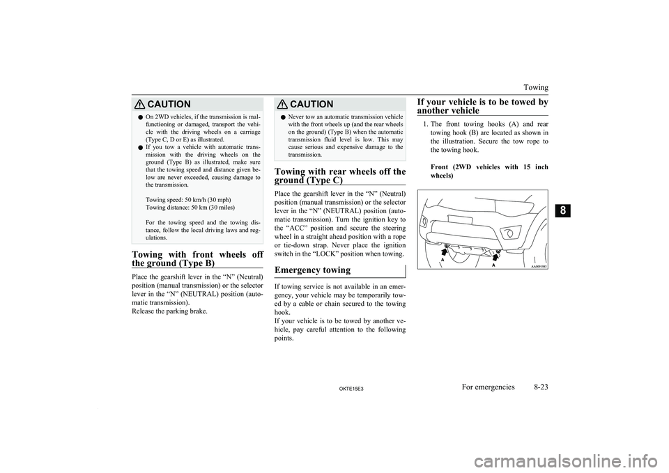
1. The front towing hooks (A) and rear
towing hook (B) are located as shown inthe illustration. Secure the tow rope to
the towing hook.
Front (2WD vehicles with 15 inch wheels)Towing
8-23OKTE15E3For emergencies8
Page 332 of 418
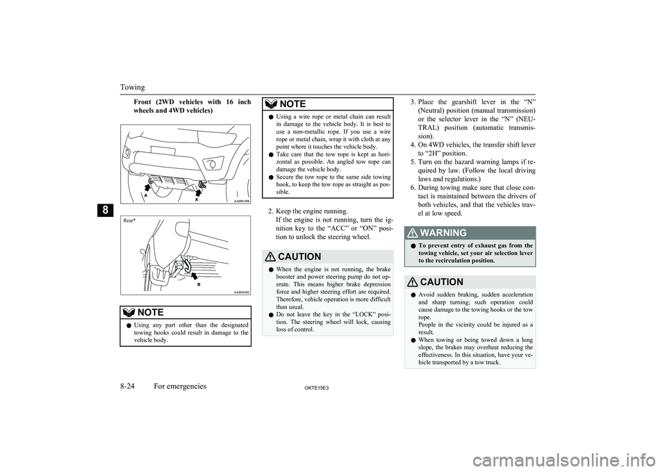
Front (2WD vehicles with 16 inchwheels and 4WD vehicles)Rear*
NOTEl Using any part other than the designated
towing hooks could result in damage to the
vehicle body.NOTEl Using a wire rope or metal chain can result
in damage to the vehicle body. It is best to use a non-metallic rope. If you use a wire
rope or metal chain, wrap it with cloth at any
point where it touches the vehicle body.
l Take care that the tow rope is kept as hori-
zontal as possible. An angled tow rope can
damage the vehicle body.
l Secure the tow rope to the same side towing
hook, to keep the tow rope as straight as pos-
sible.
2. Keep the engine running.
If the engine is not running, turn the ig-
nition key to the “ACC” or “ON” posi- tion to unlock the steering wheel.
CAUTIONl When the engine is not running, the brake
booster and power steering pump do not op- erate. This means higher brake depression
force and higher steering effort are required.
Therefore, vehicle operation is more difficult than usual.
l Do not leave the key in the “LOCK” posi-
tion. The steering wheel will lock, causing loss of control.3. Place the gearshift lever in the “N”
(Neutral) position (manual transmission) or the selector lever in the “N” (NEU-
TRAL) position (automatic transmis-
sion).
4. On 4WD vehicles, the transfer shift lever to “2H” position.
5. Turn on the hazard warning lamps if re-
quired by law. (Follow the local driving laws and regulations.)
6. During towing make sure that close con-
tact is maintained between the drivers of both vehicles, and that the vehicles trav-
el at low speed.WARNINGl To prevent entry of exhaust gas from the
towing vehicle, set your air selection lever to the recirculation position.CAUTIONl Avoid sudden braking, sudden acceleration
and sharp turning; such operation could
cause damage to the towing hooks or the tow
rope.
People in the vicinity could be injured as a
result.
l When towing or being towed down a long
slope, the brakes may overheat reducing the effectiveness. In this situation, have your ve-hicle transported by a tow truck.
Towing
8-24OKTE15E3For emergencies8
Page 344 of 418
Service precautionsE01000100706
Adequate care of your vehicle at regular in- tervals serves to preserve the value and ap-
pearance as long as possible.
Maintenance items as described in this own- er’s manual can be performed by the owner.We recommend you to have the periodic in-
spection and maintenance performed by a MITSUBISHI MOTORS Authorized Service
Point or another specialist.
In the event a malfunction or other problem is discovered, we recommend you to have it
checked and repaired. This section contains information on inspection maintenance pro- cedures that you can do yourself. Follow the
instructions and cautions for each of the vari- ous procedures.WARNINGl When checking or servicing the inside of
the engine compartment, make sure the
engine is switched off and has had a chance to cool down.
l If it is necessary to do work in the engine
compartment with the engine running, be
especially careful that your clothing, hair, etc., does not become caught by the fans,
drive belts, or other moving parts.WARNINGl For vehicle with air conditioning, the fan
may turn on automatically even if the en-
gine is not running; turn the ignition key
to “LOCK” position and remove the key to ensure safety while you work in the en-
gine compartment.
l Do not smoke, cause sparks or allow open
flames around fuel or battery. The fumesare flammable.
l Be extremely cautious when working
around the battery. It contains poisonous
and corrosive sulphuric acid.
l Do not get under your vehicle with just
the body jack supporting it. Always use
automotive jack stands.
l Improper handling of components and
materials used in the vehicle can endanger
your personal safety. We recommend you to consult a specialist for necessary infor-
mation.Catalytic converter
E01000200925
For ordinary use, there are no particular pre-cautions.
The exhaust gas scavenging devices used
with the catalytic converter are extremely ef- ficient for the reduction of noxious gases.
The catalytic converter is installed in the ex- haust system.
It is important to keep the engine properly
tuned to ensure proper catalyst operation andprevent possible catalyst damage.CAUTIONl Damage to the catalytic converter can result
if your vehicle is not kept in proper operat-ing condition. In the event of an engine mal-
function particularly involving engine mis-
fire or other apparent loss of performance, have your vehicle serviced promptly.
Continued operation of your vehicle with a
severe overheated condition may result in possible damage to the converter and vehi-cle.WARNINGl As with any vehicle, do not park or oper-
ate this vehicle in areas where combusti-
ble materials such as dry grass or leaves
can come in contact with a hot exhaust since a fire could occur.
l Paint should not be applied to the catalyt-
ic converter.
The catalytic converter itself gets hot quickly,
and may be damaged if overheated. The fol- lowing points should be noted in order to pre-vent the ignition of unburned fuel within the
catalytic converter.
Service precautions
10-02OKTE15E3Maintenance10