stop start MITSUBISHI L200 2017 (in English) Service Manual
[x] Cancel search | Manufacturer: MITSUBISHI, Model Year: 2017, Model line: L200, Model: MITSUBISHI L200 2017Pages: 426, PDF Size: 14.12 MB
Page 176 of 426
CAUTIONlDo not install any aftermarket limited-slip
differential (LSD) on your vehicle. The Ac-
tive Stability Control function may stop functioning properly.NOTEl An operation noise may be emitted from the
engine compartment in the following situa-
tions. The sound is associated with checking the operations of the ASTC. At this time,
you may feel a shock from the brake pedal if
you depress it. These do not indicate a mal- function.
• When the ignition switch is set to the
“ON” position or the operation mode is put in ON.
• When the vehicle is driven for a while af-
ter the engine is turned on.
l When the ASTC is activated, you may feel a
vibration in the vehicle body or hear a whin-
ing sound from the engine compartment.
This indicates that the system is operating normally. It does not indicate a malfunction.
l When the anti-lock brake system warning
lamp is illuminated, the ASTC is not active.NOTEl On vehicles with the rear differential lock,
the ASTC and ABS functions are suspended
while the rear differential lock is activated. ASTC indication lamp, ASTC OFF indica-
tion lamp and ABS warning lamp are illumi- nated while these functions are suspended. It
does not indicate a problem. When the rear differential lock is disengaged, these lamps
go out and function again.
Refer to “ABS warning lamp” on page 6-57,
“ASTC indication lamp, ASTC OFF indica-
tion lamp” on page 6-62.Active Stability Control func-
tion
E00616901200
The Active Stability Control function is de- signed to help the driver maintain control of the vehicle on slippery roads or during rapid
steering manoeuvres. It works by controlling the engine output and brake on each wheel.
NOTEl The Active Stability Control function does
not operate when the drive mode-selector isin the “4L” position (Easy select 4WD),“4LLc” position (Super select 4WD II).
When the Active Stability Control function
is operating with the drive mode-selector in the “2H” or “4H” position (Easy select
4WD), “2H”, “4H” or “4HLc” position (Su-
per select 4WD II), setting the drive mode- selector to the “4L” (Easy select 4WD), “4LLc” position (Super select 4WD II) posi-
tion makes the Active Stability Control func-
tion deactivate automatically.
l The Active Stability Control function oper-
ates at speeds of about 15 km/h (9 mph) or
higher.
l On vehicles with rear differential locks, the
Active Stability Control function does notoperate when the rear differential lock is ac-
tivated.“ASC OFF” switch
E00639800036
The Active Stability Control function is auto-
matically activated when the ignition switchis turned to the “ON” position or the opera-
tion mode is put in ON. You can deactivate
the system by pressing down the “ASC OFF”
switch for 3 seconds or longer.
Active Stability & Traction Control (ASTC)*
6-60OKTE17E1Starting and driving6
Page 177 of 426
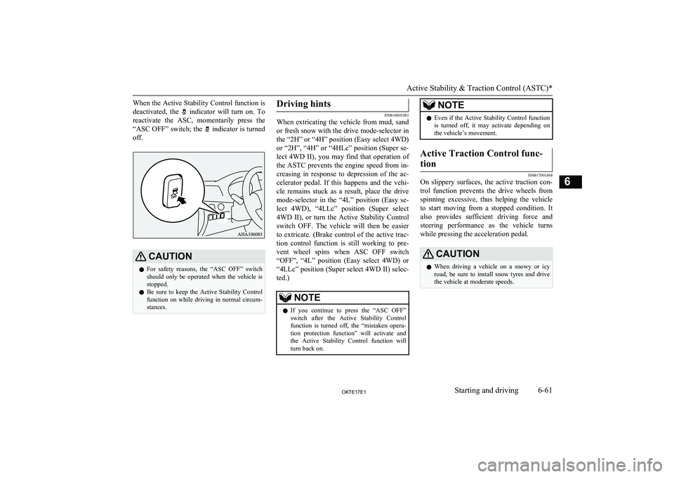
When the Active Stability Control function isdeactivated, the
indicator will turn on. To
reactivate the ASC, momentarily press the “ASC OFF” switch; the
indicator is turned
off.
CAUTIONl For safety reasons, the “ASC OFF” switch
should only be operated when the vehicle isstopped.
l Be sure to keep the Active Stability Control
function on while driving in normal circum-
stances.Driving hints
E00616801081
When extricating the vehicle from mud, sand
or fresh snow with the drive mode-selector in
the “2H” or “4H” position (Easy select 4WD) or “2H”, “4H” or “4HLc” position (Super se-
lect 4WD II), you may find that operation of
the ASTC prevents the engine speed from in- creasing in response to depression of the ac-celerator pedal. If this happens and the vehi-cle remains stuck as a result, place the drive
mode-selector in the “4L” position (Easy se- lect 4WD), “4LLc” position (Super select4WD II), or turn the Active Stability Control
switch OFF. The vehicle will then be easier
to extricate. (Brake control of the active trac- tion control function is still working to pre-
vent wheel spins when ASC OFF switch “OFF”, “4L” position (Easy select 4WD) or“4LLc” position (Super select 4WD II) selec-
ted.)
NOTEl If you continue to press the “ASC OFF”
switch after the Active Stability Control
function is turned off, the “mistaken opera- tion protection function” will activate and the Active Stability Control function will
turn back on.NOTEl Even if the Active Stability Control function
is turned off, it may activate depending on
the vehicle’s movement.Active Traction Control func-
tion
E00617001048
On slippery surfaces, the active traction con- trol function prevents the drive wheels from spinning excessive, thus helping the vehicle
to start moving from a stopped condition. It
also provides sufficient driving force and
steering performance as the vehicle turns while pressing the acceleration pedal.
CAUTIONl When driving a vehicle on a snowy or icy
road, be sure to install snow tyres and drive
the vehicle at moderate speeds.
Active Stability & Traction Control (ASTC)*
6-61OKTE17E1Starting and driving6
Page 178 of 426
ASTC indication lamp, ASTCOFF indication lamp
E00617101166
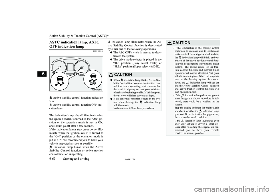
Active stability control function indication
lamp
Active stability control function OFF indi-
cation lamp
The indication lamps should illuminate when the ignition switch is turned to the “ON” po-
sition or the operation mode is put in ON, and should go off after a few seconds.
If the indication lamps stay on or do not illu-
minate when the ignition switch is turned to the “ON” position or the operation mode is put in ON, we recommend you to have your
vehicle inspected as soon as possible.
indication lamp blinks when the Active
Stability Control function or active traction
control function is operating.
indication lamp illuminates when the Ac-
tive Stability Control function is deactivated by either one of the following operations:
l The ASC OFF switch is pressed to deac-
tivated the system.
l The drive mode-selector is placed in the
“4L” position (Easy select 4WD) or “4LLc” position (Super select 4WD II).CAUTIONl When
indication lamp blinks, Active Sta-
bility Control function or active traction con-
trol function is operating, which means that
the road is slippery or that your vehicle’s
wheels are beginning to slip. If this happens, drive slower with less accelerator input.
l If an abnormal condition occurs in the sys-
tem while driving, the
indication lamp
will illuminate.
In these cases, follow these procedures:
CAUTION• If the temperature in the braking system
continues to increase due to continuous
brake control on a slippery road surface,
the
indication lamp will blink, and op-
eration of the active traction control func-
tion will be suspended to protect the brake
system. (The engine control of the trac- tion control function and normal brake operation will not be affected.) Park yourvehicle in a safe place. When the tempera-
ture in the braking system has come
down, the
indication lamp will go off
and the Active Stability Control function and active traction control function willstart operating again.
• If the
indication lamp does not go out
even though the above procedure is fol-
lowed, there could be a problem in the system.
Stop the engine and start the engine again
and check whether the
indication lamp
goes out. If the indication lamp goes out, there is no abnormal condition.
If the
indication lamp illuminates even
after your vehicle is driven a short dis-
tance after re-starting the engine, we rec-
ommend you to have your vehicle checked as soon as possible.
Active Stability & Traction Control (ASTC)*
6-62OKTE17E1Starting and driving6
Page 186 of 426
If the vehicle speed exceeds the set speed,control state “LIMIT” and the Speed Limit-
er’s symbol will blink in the combination me-
ter.
If the vehicle speed exceeds the set speed af- ter indicated control state “LIMIT” and the
Speed Limiter’s symbol, beep alert will sound a certain period of time.
While running without blinked control state “LIMIT” and the Speed Limiter’s symbol, if
you decrease the set speed and vehicle speed is more than set speed, control state “LIMIT” and the Speed Limiter’s symbol blinking
starts but beep alert is delayed.
In this case, when vehicle speed keeps ex- ceeding set speed for about 30 seconds after
control state “LIMIT” and the Speed Limit- er’s symbol are blinked, beep alert will sound
a certain period of time.
If the vehicle speeds decreases less than set
speeds, control state “LIMIT” and the Speed Limiter’s symbol stop blinking. When beep
alert is sounding, the beep alert also goes off.NOTEl However, this gives priority to audio and
visual signal of safety reasons or driver’s de-mand.NOTEl If the set speed is too lower based on current
shift position, the Speed Limiter may notlimit the vehicle speed to prevent engine
stall.Speed Limiter control switches
E00633301094
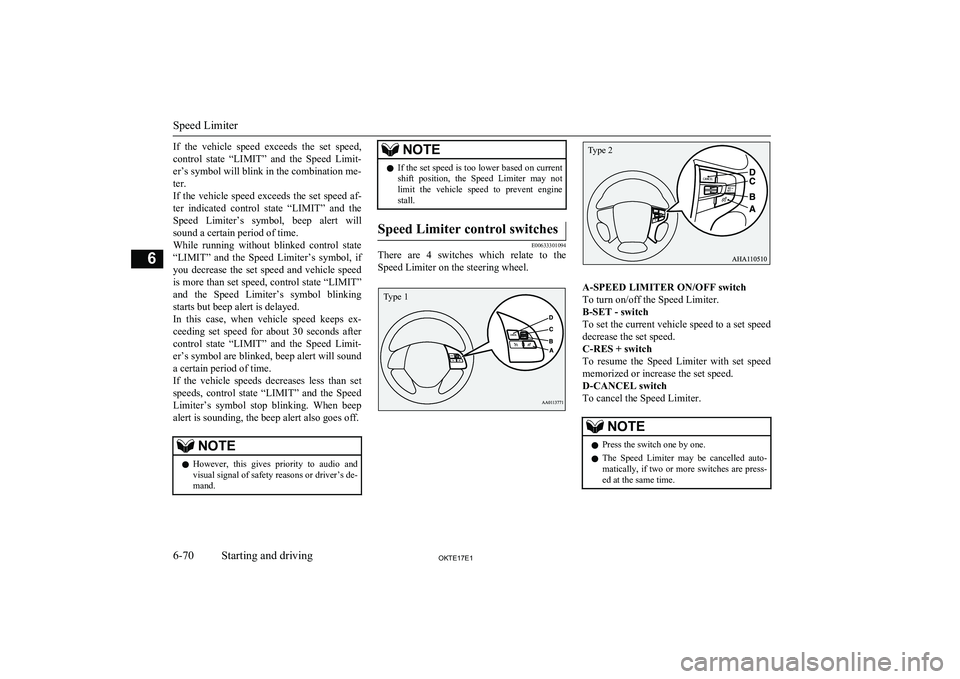
There are 4 switches which relate to the
Speed Limiter on the steering wheel.
A-SPEED LIMITER ON/OFF switch
To turn on/off the Speed Limiter.
B-SET - switch
To set the current vehicle speed to a set speed decrease the set speed.
C-RES + switch
To resume the Speed Limiter with set speed memorized or increase the set speed.
D-CANCEL switch
To cancel the Speed Limiter.
NOTEl Press the switch one by one.
l The Speed Limiter may be cancelled auto-
matically, if two or more switches are press-ed at the same time.
Speed Limiter
6-70OKTE17E1Starting and driving6 Type 1 Type 2
Page 191 of 426
The Speed Limiter will resume when the ve-hicle speed goes down to enough less than
the set speed.
Put on an accelerator pedal to the pedal
stroke end. (over a detent that makes pedal reaction force bigger before pedal stroke end)
CAUTIONl There is a possibility for the Speed Limiter
to allow abrupt acceleration corresponding
to accelerator pedal position. So be careful
of the abrupt acceleration.If the vehicle speed exceeds the set speed, the
control state “LIMIT” and the Speed Limit-
er’s symbol will blink.CAUTIONl Be careful about over speed.NOTElA driver can change the set speed during this
emergency use.To deactivate
E00634401089
Use whichever following ways to deactivate.
l Press the CANCEL switch
l Press the Speed Limiter ON/OFF switch
NOTElIf the Speed Limiter is cancelled by other
states, it may be a system malfunction.
Stop using the Speed Limiter and turn off
the Speed Limiter. Have your vehicle in-
spected by a MITSUBISHI MOTORS Serv-
ice Point.CAUTIONl There is a possibility for the Speed Limiter
to allow abrupt acceleration corresponding
to accelerator pedal position when the Speed Limiter is deactivated. Be careful.To resume
E00634501077
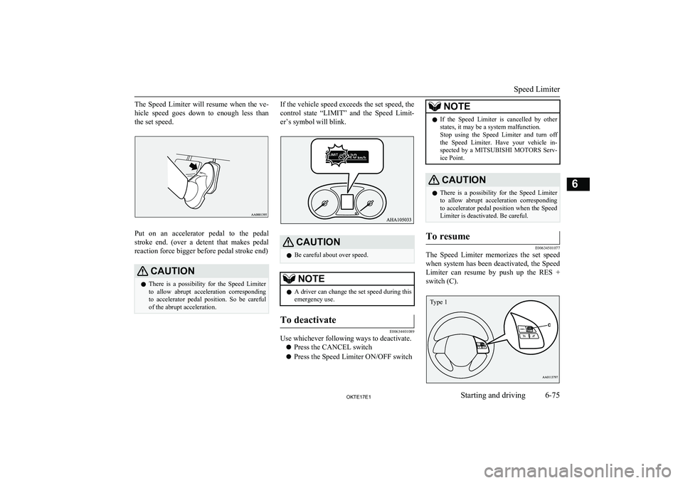
The Speed Limiter memorizes the set speed
when system has been deactivated, the Speed
Limiter can resume by push up the RES +
switch (C).
Speed Limiter
6-75OKTE17E1Starting and driving6 Type 1
Page 193 of 426
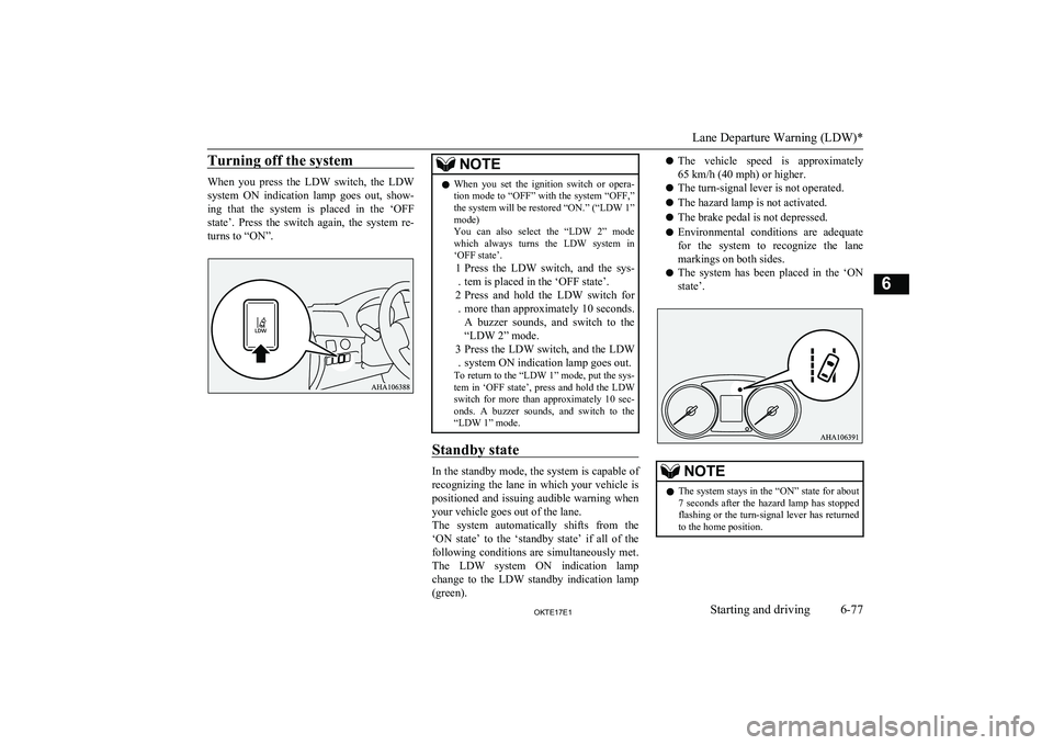
Turning off the system
When you press the LDW switch, the LDW
system ON indication lamp goes out, show-
ing that the system is placed in the ‘OFF
state’. Press the switch again, the system re- turns to “ON”.
NOTEl When you set the ignition switch or opera-
tion mode to “OFF” with the system “OFF,”
the system will be restored “ON.” (“LDW 1”
mode)
You can also select the “LDW 2” mode
which always turns the LDW system in ‘OFF state’.
1
. Press the LDW switch, and the sys-
tem is placed in the ‘OFF state’.
2 . Press and hold the LDW switch for
more than approximately 10 seconds. A buzzer sounds, and switch to the
“LDW 2” mode.
3 . Press the LDW switch, and the LDW
system ON indication lamp goes out.
To return to the “LDW 1” mode, put the sys-
tem in ‘OFF state’, press and hold the LDW switch for more than approximately 10 sec-onds. A buzzer sounds, and switch to the
“LDW 1” mode.
Standby state
In the standby mode, the system is capable of
recognizing the lane in which your vehicle is positioned and issuing audible warning whenyour vehicle goes out of the lane.
The system automatically shifts from the
‘ON state’ to the ‘standby state’ if all of the following conditions are simultaneously met.
The LDW system ON indication lamp change to the LDW standby indication lamp
(green).
l The vehicle speed is approximately
65 km/h (40 mph) or higher.
l The turn-signal lever is not operated.
l The hazard lamp is not activated.
l The brake pedal is not depressed.
l Environmental conditions are adequate
for the system to recognize the lanemarkings on both sides.
l The system has been placed in the ‘ON
state’.NOTEl The system stays in the “ON” state for about
7 seconds after the hazard lamp has stopped
flashing or the turn-signal lever has returned to the home position.
Lane Departure Warning (LDW)*
6-77OKTE17E1Starting and driving6
Page 194 of 426
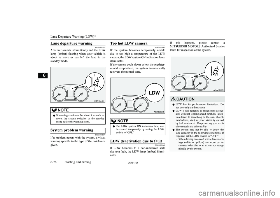
Lane departure warning
E00638600053
A buzzer sounds intermittently and the LDW
lamp (amber) flashing when your vehicle is about to leave or has left the lane in the
standby mode.NOTEl If warning continues for about 3 seconds or
more, the system switches to the standby
mode before the warning stops.System problem warning
E00635901078
If a problem occurs with the system, a visual
warning specific to the type of the problem isgiven.
Too hot LDW camera
E00638700041
If the system becomes temporarily unable
due to too high a temperature of the LDWcamera, the LDW system ON indication lamp
illuminates.
If the camera cools down below the predeter-
mined temperature, the system automatically recovers the normal state.NOTEl The LDW system ON indication lamp can
be cleared temporarily by setting the LDW switch to “OFF.”LDW deactivation due to fault
E00638800068
If LDW becomes to a non-initialized state
due to a fault, the LDW lamp (amber) illumi-
nates.
If this happens, please contact a
MITSUBISHI MOTORS Authorized Service
Point for inspection of the system.CAUTIONl LDW has its performance limitations. Do
not over-rely on the system.
l LDW is not designed to lessen risks associ-
ated with not looking ahead carefully (atten-
tion drawn to something on the side, absent-
mindedness, etc.) or poor visibility caused
by bad weather etc. Keep steering your vehi-
cle correctly and drive safely.
l The system may not be able to detect the
lane correctly in the following conditions. If required, set the LDW switch to “OFF.”
• When driving on a road whose lane mark-
ings (white or yellow) are worn out or
smeared with dirt to an extent not recog- nizable by the system.
Lane Departure Warning (LDW)*
6-78OKTE17E1Starting and driving6
Page 197 of 426
NOTElBecause the rear-view camera has a special
lens, the lines on the ground between park-
ing spaces may not look parallel on the screen.
l In the following situations, the screen indi-
cation may be difficult to see. There is no abnormality.
• Low light (nighttime).
• When the light of the sun or the light from
a vehicle’s headlamps shines directly into
the lens.
• If a fluorescent light shines directly into
the lens, the screen indication may be
flicker.
There is no abnormality.
l If the camera is hot and is then cooled by
rain or a car wash, the lens can mist up. This
phenomenon does not indicate a malfunc- tion.
l If the atmospheric temperature is extremely
hot or extremely cold, the rear-view camera
images may not be clear.
There is no abnormality.
l If a radio set is installed near the camera, the
rear-view camera images may cause electri- cal system interference and the system may
stop functioning properly.
l It is not possible to fully see obstacles when
the lens is dirty. If the lens becomes conta-
minated by water droplets, snow, mud or oil, wipe off the contamination, taking care not
to scratch the lens.
l Please observe the following cautions. Ig-
noring them could lead to a camera malfunc-tion.NOTE• Do not subject the camera to a physical
shook such as striking it strongly or
throwing a thing at it.
• Do not adhere organic substances, waxes,
oil remover, and glass cleaner to the cam- era.
If adhered to them, immediately wipe off.
• Do not splash the camera with boiling wa-
ter.
• Never spray or splash water on the cam-
era or around it.
• Do not disconnect, disassemble or modify
the camera.
• Do not scratch the camera, as this may
cause damage to the rear-view camera im-
ages.
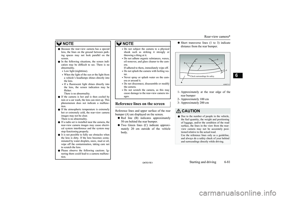
Reference lines on the screen
Reference lines and upper surface of the rear
bumper (A) are displayed on the screen.
l Red line (B) indicates approximately
50 cm behind the rear bumper.
l Two Green lines (C) indicate approxi-
mately 20 cm outside of the vehicle
body.
l Short transverse lines (1 to 3) indicate
distance from the rear bumper.Check surroundings for safety.
1- Approximately at the rear edge of the
rear bumper
2- Approximately 100 cm
3- Approximately 200 cm
CAUTIONl Due to the number of people in the vehicle,
the fuel quantity, the weight and positioning
of luggage, and/or the condition of the road surface, the lines in the view from the rear- view camera may not be accurately posi-
tioned relative to the actual road.
Use the reference lines only as a guideline, and always do a safety check of your behind
and surroundings directly while driving.
Rear-view camera*
6-81OKTE17E1Starting and driving6
Page 201 of 426
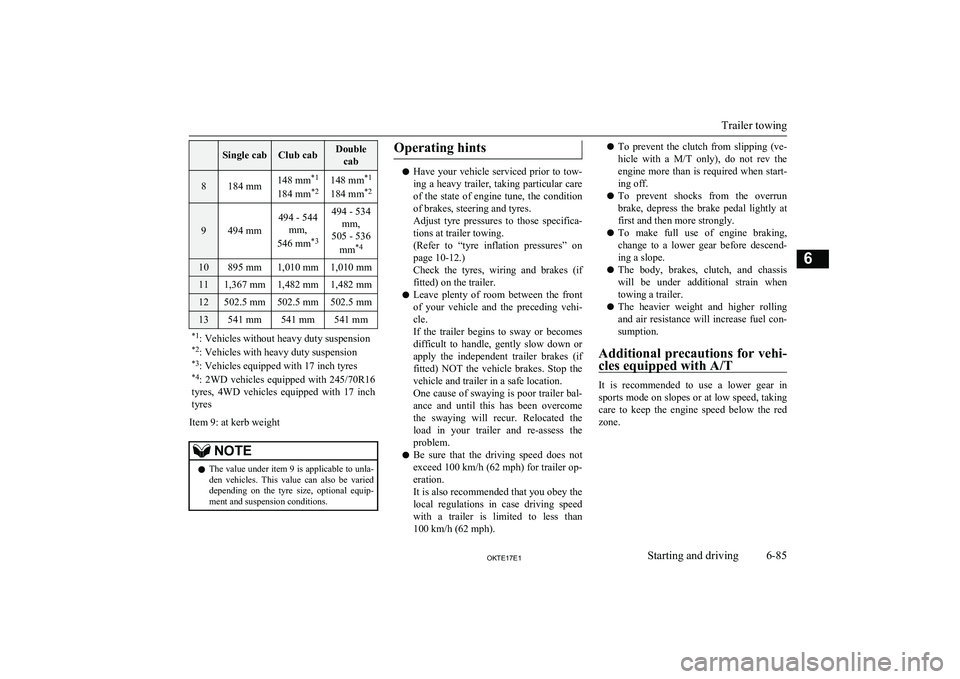
Single cabClub cabDoublecab8184 mm148 mm *1
184 mm *2148 mm *1
184 mm *2
9494 mm
494 - 544
mm,
546 mm *3494 - 534
mm,
505 - 536
mm *410895 mm1,010 mm1,010 mm111,367 mm1,482 mm1,482 mm12502.5 mm502.5 mm502.5 mm13541 mm541 mm541 mm*1
: Vehicles without heavy duty suspension
*2 : Vehicles with heavy duty suspension
*3 : Vehicles equipped with 17 inch tyres
*4 : 2WD vehicles equipped with 245/70R16
tyres, 4WD vehicles equipped with 17 inch
tyres
Item 9: at kerb weight
NOTEl The value under item 9 is applicable to unla-
den vehicles. This value can also be varied depending on the tyre size, optional equip-
ment and suspension conditions.Operating hints
l Have your vehicle serviced prior to tow-
ing a heavy trailer, taking particular care
of the state of engine tune, the condition of brakes, steering and tyres.
Adjust tyre pressures to those specifica- tions at trailer towing.
(Refer to “tyre inflation pressures” on
page 10-12.)
Check the tyres, wiring and brakes (if fitted) on the trailer.
l Leave plenty of room between the front
of your vehicle and the preceding vehi- cle.
If the trailer begins to sway or becomes difficult to handle, gently slow down or
apply the independent trailer brakes (if fitted) NOT the vehicle brakes. Stop the
vehicle and trailer in a safe location.
One cause of swaying is poor trailer bal-
ance and until this has been overcome the swaying will recur. Relocated the load in your trailer and re-assess the
problem.
l Be sure that the driving speed does not
exceed 100 km/h (62 mph) for trailer op-
eration.
It is also recommended that you obey the
local regulations in case driving speed with a trailer is limited to less than
100 km/h (62 mph).
l To prevent the clutch from slipping (ve-
hicle with a M/T only), do not rev the
engine more than is required when start-
ing off.
l To prevent shocks from the overrun
brake, depress the brake pedal lightly at
first and then more strongly.
l To make full use of engine braking,
change to a lower gear before descend-
ing a slope.
l The body, brakes, clutch, and chassis
will be under additional strain when
towing a trailer.
l The heavier weight and higher rolling
and air resistance will increase fuel con- sumption.
Additional precautions for vehi-
cles equipped with A/T
It is recommended to use a lower gear in
sports mode on slopes or at low speed, taking care to keep the engine speed below the red
zone.
Trailer towing
6-85OKTE17E1Starting and driving6
Page 206 of 426
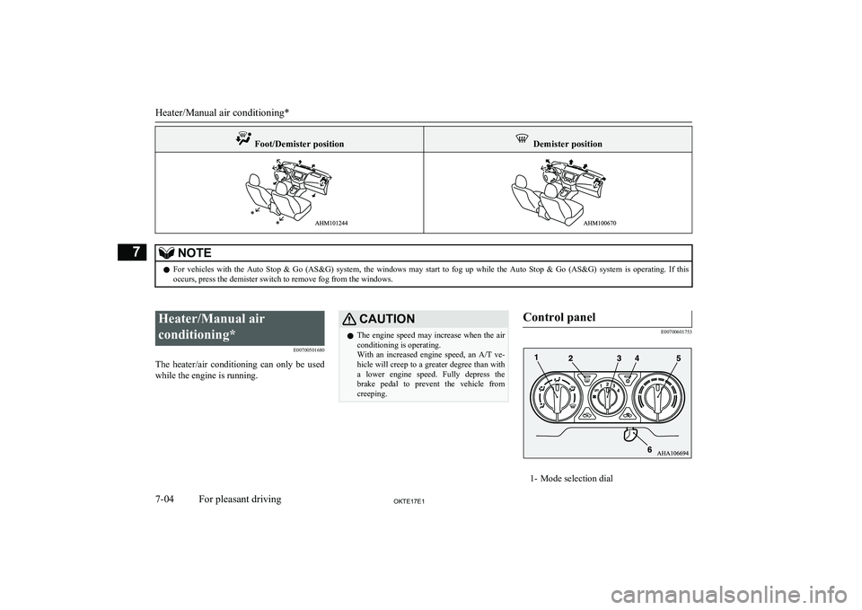
Foot/Demister position Demister positionNOTElFor vehicles with the Auto Stop & Go (AS&G) system, the windows may start to fog up while the Auto Stop & Go (AS&G) system is operating. If this
occurs, press the demister switch to remove fog from the windows.
Heater/Manual air
conditioning* E00700501680
The heater/air conditioning can only be used while the engine is running.CAUTIONl The engine speed may increase when the air
conditioning is operating.
With an increased engine speed, an A/T ve-
hicle will creep to a greater degree than with a lower engine speed. Fully depress the brake pedal to prevent the vehicle from
creeping.Control panel
E00700601753
1- Mode selection dial
Heater/Manual air conditioning*
7-04OKTE17E1For pleasant driving7